Calculation of the diameter of the V-belt pulley
how to correctly calculate the diameters of the pulleys so that the knife shaft of a woodworking machine rotates at a speed of 3000...3500 rpm.
The rotational speed of the electric motor is 1410 rpm (the motor is three-phase, but will be connected to a single-phase network (220 V) using a capacitor system. V-belt. The pulley diameter, depending on the shaft rotation speed and the linear speed of the pulley, is determined by the formula:
where D1 is the pulley diameter, mm; V is the linear speed of the pulley, m/s; n—shaft rotation speed, rpm.
It is easy to calculate that for a pulley on the shaft of an electric motor with a rotation speed of 1400 rpm, the minimum diameter of the pulley (overdrive) at a linear belt speed of 10 m/s will be about 136 mm.
The diameter of the driven pulley is calculated using the following formula:
where D1 and D2 are the diameters of the driving and driven pulleys, mm; ε—belt slip coefficient equal to 0.007…0.02; n1 and n2 - rotation speed of the drive and driven shafts, rpm.
Since the value of the slip coefficient is very small, the slip correction can be ignored, that is, the above formula will take on a simpler form:
The minimum distance between pulley axes (minimum center distance) is:
where Lmin is the minimum center-to-center distance, mm; D1 and D2 - pulley diameters, mm; h is the height of the belt profile.
The smaller the center-to-center distance, the more the belt bends during operation and the shorter its service life. It is advisable to take the center-to-center distance greater than the minimum value Lmin, and the closer the gear ratio is to unity, the larger it becomes. However, to avoid excessive vibration, very long belts should not be used. By the way, the maximum center-to-center distance Lmax can be easily calculated using the formula:
Lmax
Source
Gearbox connection process
The engine is dismantled.
The pulley is removed from it. You need to make an adapter coupling under its shaft. On one side it should be put on the shaft, and on the other it should be equipped with an M14 internal thread.
It is best to turn the coupling on a lathe. If it is absent, you can cut an M14 thread in the workpiece up to half and screw it onto the grinder. Then the blank is ground on a sanding belt and drilled from the free end. Moreover, it is she who should rotate due to the grinder, the drill itself remains motionless. A coupling made this way will have a balance no worse than one turned on a lathe.
The gearbox is removed from an old grinder. You need to cut its armature in half, and then free the input shaft.
A base is made of sheet steel under the engine. It is installed on it. Using a coupling, the secondary shaft of the angle grinder is connected to it. To mount the gearbox, an adapter plate is made from sheet steel, which is welded to the base.
The engine is connected via a speed controller. Now, when starting, the shaft on the gearbox will rotate 3 times faster, which will allow you to attach a flexible shaft to the drill. If you connect the gearbox in reverse, the force will increase 3 times, but the speed will drop.
Magnification – diameter – pulley
The diameter of the pulleys of the traveling system should be 38 - 42 times the diameter of the rope. Increasing the diameters of the pulleys helps reduce friction losses and improve the operating conditions of the rope. [18]
Belt drives (Fig. 47) require round, flat and V-belts. When the diameter of the drive shaft pulley increases, the number of revolutions of the driven shaft increases, and, conversely, if the diameter of the drive shaft pulley is reduced, the number of revolutions of the driven shaft also decreases. [20]
The cyclically changing stress that arises in a rectilinear belt traction element is largely determined by the magnitude of the bending stress that appears in the tape when it rolls over pulleys and reels. The amount of bending stress can be reduced by thickness of the belt or by increasing the diameter of the pulley. However, the thickness of the tape has a minimum limit, and an increase in the diameter of the pulley is undesirable due to a significant increase in the weight of the winding element and the overall cost of the lifting installation. [25]
The necessary pre-tension of the ropes is determined depending on their condition: a distinction is made between a new rope and a rope that has already been stretched under load. As the transmission operates, the ropes gradually lengthen and their sag increases. In this case, the decrease in tension m, caused by the pre-tension of the rope, is partially replaced by an increase in tension from an increase in the weight of the sagging part of the rope, and to a greater extent, the greater the sag of the rope. More favorable conditions for rope operation are created by increasing the diameters of the pulleys and using elastic ropes. When installing transmission at distances of 25 - 30 m, intermediate pulleys are installed (Fig. The use of support pulleys, as already mentioned, leads to a decrease in transmission efficiency. [27]
some bad questions: a pulley is placed on the motor depending on the user, you determine how many revolutions it should have and select the appropriate pulleys
for example, if the engine has 2950 revolutions, then if the pulley on the consumer is twice as large, then it will have 1475 revolutions
I had to study at school: engine power depends on active and reactance (what is designated cosfi on the engine nameplate)
it does not depend on the size of the pulley. When a load is applied to the engine, it consumes one power, and another when idling. a 200 kW engine can consume 160 kW in operating mode, or maybe 220, and both are standard operating modes for it
A belt drive transmits torque from the drive shaft to the driven shaft. Depending on the gear ratio, it can increase or decrease the speed. The gear ratio depends on the ratio of the diameters of the pulleys - drive wheels connected by a belt. When calculating the drive parameters, you must also take into account the power on the drive shaft, its rotation speed and the overall dimensions of the device.
Usage
CNC units equipped with a flat-belt transmission are used as machine tools, sawmills, generators, fans, as well as in other areas where the operation of devices with an increased level of flexibility and the ability to slip is required. If the equipment is used at high speeds, synthetic materials are used. At lower speeds, cord fabric and rubberized belts are used.
Wedge-type analogues are used in the agricultural industry. Transmissions of various cross-sections can withstand high loads and high speeds. Industrial class machines require the use of CVTs. Toothed belts have the best characteristics. They are used in both industrial and domestic areas. Round belt drives are used for low-power devices.
The main disadvantage of CNC belt drive is the quality of the belt. Even the highest quality products tend to stretch. Long types stretch the fastest. Tools on stretched belts cannot provide high precision processing. The stretching effect can be reduced by attaching two straps to each other. Only a certain segment is stretched, so this drawback is not so dangerous.
This type of transmission provides soft movements without resonance. Dust and chips cannot negatively affect its operation. It is possible to tension the belt.
There are several factors to remember when using a CNC machine:
- toothed belts ensure movement of the moving parts of the unit;
- belts are divided into closed and open;
- polyurethane belts are more wear-resistant;
- On CNC machines, the use of reinforced belts is allowed.
This type of transmission on CNC machines at high speeds can reduce power levels and accuracy. This drawback can be solved by installing special equipment. After installing them, you may need to configure the drivers. This action is required in order to smooth out the operation of the unit. This is done in the program settings. The value for pulleys to ensure proper movement depends on which model of machine, or ball screw, is selected.
For numerically controlled units using a belt drive, no special software is required. The program is compiled and developed depending on the type of work it is needed for. In order for the device to work properly in offline mode, you should periodically check its condition. The program cannot solve the problem of faulty hardware.
Belt drive device, its characteristics
A belt drive consists of a pair of pulleys connected by an endless looped belt. These drive wheels are usually placed in the same plane, and the axles are made parallel, with the drive wheels rotating in the same direction. Flat (or round) belts allow you to change the direction of rotation due to crossing, and the relative position of the axes through the use of additional passive rollers. In this case, part of the power is lost.
V-belt drives, due to the wedge-shaped cross-section of the belt, make it possible to increase the area of engagement with the belt pulley. A wedge-shaped groove is made on it.
Toothed belt drives have teeth of equal pitch and profile on the inside of the belt and on the surface of the rim. They do not slip, allowing more power to be transmitted.
The following basic parameters are important for calculating the drive:
Calculations are usually carried out in several stages.
Multi-stage transmission
To increase the kinematic effect, several gear pairs can be connected in series into a single mechanism. This mechanism is called a multi-stage gear mechanism or multi-stage transmission
. A diagram of one of these mechanisms is shown in Figure 36.
Let us write down the gear ratios for each pair of wheels of this mechanism:
From the diagram it is clear that wheels 2 and 3 are on the same shaft and rotate at the same angular speed (ω2 = ω3), similar to ω4 = ω5. Therefore, in the above equation, these terms have been canceled out.
Thus, the general gear ratio of a multi-stage mechanism is equal to the product of the private gear ratios of the stages that make up the mechanism:
In this formula, “m” is the number of external gears (if the number of external gears is even, then the sign is “+”, i.e. the wheels at the input and output rotate in the same direction; if it is odd, then the sign is “–”. Number internal gears are not taken into account, since internal gear does not change the direction of rotation).
In the given example, m=2 (pairs Z1* Z2 and Z3* Z4; pair Z5* Z6 – pair of internal gearing) and, thus, wheels “1” and “6” rotate in the same direction.
Main diameters
To calculate the parameters of pulleys, as well as the drive as a whole, different diameter values are used, for example, for a V-belt pulley, the following are used:
To calculate the gear ratio, the design diameter is used, and the outer diameter is used to calculate the dimensions of the drive when configuring the mechanism.
For a toothed belt drive, Dcalc differs from Dout by the height of the tooth. The gear ratio is also calculated based on the value of Dcalc.
To calculate a flat belt drive, especially with a large rim size relative to the profile thickness, Dcalc is often taken equal to the outer one.
How to correctly measure the length of a belt?
How to determine belt size?
- measure the circumference of the waistband of your trousers with a sewing tape measure or tape measure and buy a belt 3-5 centimeters longer.
- Measure your old belt using a measuring tape, determining the length from the buckle attachment point to the hole that was used most often for comfortable fastening.
2 Feb
2022 Interesting materials:
What is the significance of ants in nature? Which pot should I transplant my Phalaenopsis orchid into? What pot should I plant my Phalaenopsis orchid in? How long does it take to register a lease agreement? How long does it take to cancel a court order? How much is the salary advance paid? Which bank has the world card? In which bank can I deposit money on a halva card? In what year was the city of Tomsk founded? In what year was Leningrad renamed?
Pulley diameter calculation
First, you should determine the gear ratio based on the specified rotation speed of the drive shaft n1 and the required rotation speed of the driven shaft n2/ It will be equal to:
If you already have a ready-made engine with a drive wheel, the calculation of the pulley diameter according to the gear ratio i is carried out using the formula:
If the mechanism is designed from scratch, then theoretically any pair of drive wheels that satisfy the following conditions will be suitable:
In practice, the calculation of the drive wheel is carried out based on:
The final diameter calculation is finalized based on the results of dimensional and power estimates.
Machine parts
Combined couplings
These couplings are used in cases where none of the couplings discussed above can fully satisfy all the requirements for connecting shafts. In practice, a combination of elastic...
Automatic or self-controlled clutches
These couplings are designed to automatically disconnect shafts in cases where the operating parameters of the machine become unacceptable for certain indicators. The classification of automatic couplings is presented in the diagram on p. 367. The above...
Controlled or clutch couplings
Controlled couplings allow shafts to be connected or separated using a control mechanism. According to the principle of operation, all these couplings can be divided into two groups: couplings based on gearing (cam or gear); couplings...
Electric motor power by installation and overall dimensions
For the first method, you need to know the installation dimensions of the electric motor and the synchronous speed. The latter is measured using a multimeter set to milliammeter mode. To do this, set the selection wheel pointer to 100µA. We connect the black probe to the common “COM” socket, and the red probe to the socket for measuring voltage, resistance and current up to 10 A.
After this, de-energize the electric motor and remove the cover from the terminal box. We connect the multimeter probes to the beginning and end of any of the windings (for example, V1 and V2). After this, we slowly turn the motor shaft by hand so that it makes one revolution, and count the number of deviations of the needle from rest that it will make during this time. The number of pointer deflections per shaft revolution is equal to the number of poles and corresponds to the following synchronous rotation speed: • 2 poles – 3000 rpm; • 4 poles – 1500 rpm; • 6 poles – 1000 rpm; • 8 poles – 750 rpm. Now you need to find out the installation dimensions of the engine. For measurements we use calipers, mechanical or electronic, as well as a measuring tape. We record the measurement results in millimeters: the diameter and length of the shaft extension, the height of the axis of rotation, the distance between the centers of the holes in the “legs”, and if the engine is flanged, then the diameter of the flange and the diameter of the mounting holes. We compare the obtained data with the parameters from tables 1-3.
Calculation and selection of a servomotor for a ball screw pair
A servo drive, based on a synchronous motor with a feedback sensor (encoder), has become an integral part of most machine tools that require precision, high process dynamics and reliability. A lot of literature has been written about the advantages of a servo drive in comparison with other types of electric drives (asynchronous, synchronous reluctance, direct current) used in machine tool industry. The main feature of the servo drive based on a permanent magnet synchronous motor (discussed in this article) is that it can briefly provide a torque of up to 350% of the rated torque, which allows for high dynamics and the choice of a motor with a lower rated torque than in cases with other types of engines. The content of this article will be relevant for specialists who have already decided on the type of equipment, but do not know how to select a servomotor.
Very often, engineers are faced with the problem of selecting a servo motor for a particular type of application. The choice of the nominal characteristics of the engine should not be empirical in nature, since there is only one proven method - calculating the engine parameters. This calculation is made based on the operating conditions of the system and the requirements for it. The article provides a diagram (Fig. 1) and an example of calculating a YASKAWA servomotor of the SIGMA 5 series when used with a ball screw (BSC) - a converter of rotational motion into linear linear motion.
Figure 1. Kinematic diagram of the servomotor-ball screw mechanism.
Let's set the initial parameters:
- Loading speed: ϑL=15 m/min;
- Mass of elements of translational motion: m=250 kg;
- Screw length: lB=1.0 m;
- Screw diameter: dB=0.02 m;
- Screw thread pitch: PB=0.01 m;
- Ball density: ρ=7.87×〖10〗^3 kg/m3;
- Gear ratio: i=2;
- Total moment of inertia of the gearbox and coupling: JG=0.40×〖10〗^(-4) kg*m2;
- Feed frequency (movements): n=40 min-1;
- Movement (positioning) distance: l=0.275 m;
- Maximum movement (positioning) time: tm=1.2 s;
- Stopping accuracy: δ=±0.01 mm;
- Sliding friction coefficient: μ=0.2;
- Mechanical efficiency: η=0.9 (90%).
Calculating time using a linear motion graph
To accurately calculate the motor parameters for the required task, you need to draw up a cyclogram of the movement of the mechanism (working element). In this case, the movement of the working body will be cyclical.
Figure 2. Linear velocity cyclogram.
From the cyclogram it is clear that the acceleration and deceleration times have equal values, therefore, we get:
Calculation of the rotation speed of the servomotor shaft
Ball screw rotation speed: nL=ϑL/PB =15/0.01=1500 rpm;
Motor shaft rotation speed: nM=nL×i=1500×2=3000 rpm.
Calculation of the torque applied to the servomotor shaft
Calculation of the reduced moment of inertia to the servomotor shaft
Bearing moment of inertia:
Total moment of inertia of the coupling and gearbox:
Total moment of inertia:
Load power calculation
Calculation of servo motor power to ensure the required system dynamics
Servomotor preselection
A) Selecting a servomotor that satisfies the conditions:
- ML≤Nominal motor torque;
- (Pa+PO)/2 The servomotor SGMJV-02A meets these conditions.
B) Specifications of pre-selected servo motor:
- Servomotor SGMJV-02A;
- Rated power: 200 W;
- Rated speed: 3000 rpm;
- Nominal torque: 0.637 Nm;
- Peak torque: 2.23 Nm;
- Motor inertia moment: 0.259×〖10〗^(-4) kg*m2;
- Allowable moment of inertia of the load: 15×0.259×〖10〗^(-4)=3.385×〖10〗^(-4) kg*m2;
Mechanical characteristics of the engine (dependence of speed on torque):
Figure 3. Mechanical characteristics of the SGMJV-02A servomotor.
YASKAWA servomotors during acceleration and deceleration can exceed the rated torque up to 350% within 2 seconds, which corresponds to the overload characteristic of the servomotor:
Nominal design diameters dp of pulleys, mm:
50; (53); 56; (60); 63; (67); 71; (75); 80; (85); 90; (95); 100; (106); 112; (118); 125; (132); 140; (150); 160; (170); 180; (190); 200; (212); 224; (236); 250; (265); 280; (300); 315; (335); 355; (375); 400; (425); 450; 475; 500; (530); 560; (600); (620); 630; (670); 710; (750); 800; (850); 900; (950); 1000; (1060); 1120; (1180); 1250; (1320); 1400; (1500); 1600; (1700); 1800; (1900); 2000; (2120); 2240; (2360); 2500; (2650); (2800); (3000); (3150); (3550); (3750); (4000) mm.
Note. The dimensions indicated in brackets are used in technically justified cases.
Determination of power by current consumption
The power of a motor can be determined by the current it consumes. To measure the current we will use a current clamp. Before starting measurements, first turn off the voltage supply to the electric motor. After this, remove the cover from the terminal box and straighten the conductive wires to ensure easy access to them. Then we apply voltage to the engine and let it run at rated load for several minutes. We set the measurement limit to the value “200 A” and use a current clamp to measure the current consumed in one of the phases. Next, we measure the voltage on the windings using the probes included in the set of current clamps. We set the wheel for selecting modes and measurement limits to the position for measuring alternating voltage with a limit of 750 V. We attach the red probe to the socket for measuring voltage, resistance and current up to ten Amps, and the black one to the “COM” socket. Measurements are taken between terminals “U1-V1” or “V1-W1” or “U1-W1”. We calculate the power of the electric motor using the formula: S=1.73×I×U, where S is the total power (kVA), I is the current (A), U is the value of the line voltage (kV). We measure the current in one of the phases, as well as the voltage and substitute the obtained values into the formula (for example, when measuring, we received a current equal to 15.2A and a voltage of 220V): S = 1.73 × 15.2 × 0.22 = 5.78 kVA It is important to note that the power email motor does not depend on the connection diagram of the stator windings. This can be verified by taking measurements on the same motor, but with stator windings connected in a star configuration: the measured current will be 8.8A, voltage 380V. We also substitute the values into the formula: S=1.73×8.8×0.38=5.78 kVA Using this formula, we determined the electric motor power consumed from the electrical network. To find out the engine power on the shaft, you need to multiply the resulting value by the engine power factor and its efficiency. Thus, the formula for engine power looks like this: P=S×сosφ×(η÷100), where P is the engine power on the shaft; S – total engine power; сosφ – power factor of an asynchronous electric motor; η – engine efficiency. Since we do not have accurate data, we will substitute the average values of cosφ and engine efficiency into the formula: P=5.78×0.8×0.85=3.93≈4kW Thus, we have determined the power of the electric motor, which is equal to 4 kW. We talked about the most reliable methods for determining the power of an electric motor. You can also watch our video, which shows in detail how to determine the power of an electric motor.
Step-by-step instructions for replacing the free motion mechanism
The overrunning clutch can be replaced by a specialized service center or independently. When diagnosing the clutch, do not forget to check the condition of the generator - you may need to replace the armature or consumables. The free movement mechanism fasteners are usually hidden by a protective cap and recessed under a countersunk bolt. A special key is required.
- Disconnect the negative terminal of the battery.
Remove the engine protection.
Remove the alternator belt.
Install a new coupling, protective cap and cover.
- Repeat steps 1-4 in reverse order.
Conclusion
The inappropriateness of repairing the overrunning clutch is explained by its low cost. In some cases, minor repairs are performed in the form of replacing liners or rollers.
The average service life of an overrunning clutch is 100,000 km.
. However, if the vehicle is used intensively in difficult road conditions, the period can be significantly reduced. Therefore, if one of the obvious signs of a malfunction of the free movement mechanism is detected, it is necessary to diagnose the entire generator unit and replace worn parts with new ones.
As you can see, there is nothing complicated about replacing the coupling. But we still recommend that an inexperienced car enthusiast contact a specialized car service center.
Video on how to check the clutch:
How to reduce the speed of an electric motor
how to correctly calculate the diameters of the pulleys so that the knife shaft of a woodworking machine rotates at a speed of 3000...3500 rpm. The rotational speed of the electric motor is 1410 rpm (the motor is three-phase, but will be connected to a single-phase network (220 V) using a capacitor system. V-belt.
The pulley diameter, depending on the shaft rotation speed and the linear speed of the pulley, is determined by the formula:
where D1 is the pulley diameter, mm; V is the linear speed of the pulley, m/s; n—shaft rotation speed, rpm.
It is easy to calculate that for a pulley on the shaft of an electric motor with a rotation speed of 1400 rpm, the minimum diameter of the pulley (overdrive) at a linear belt speed of 10 m/s will be about 136 mm.
The diameter of the driven pulley is calculated using the following formula:
where D1 and D2 are the diameters of the driving and driven pulleys, mm; ε—belt slip coefficient equal to 0.007…0.02; n1 and n2 - rotation speed of the drive and driven shafts, rpm.
Since the value of the slip coefficient is very small, the slip correction can be ignored, that is, the above formula will take on a simpler form:
The minimum distance between pulley axes (minimum center distance) is:
where Lmin is the minimum center-to-center distance, mm; D1 and D2 - pulley diameters, mm; h is the height of the belt profile.
The smaller the center-to-center distance, the more the belt bends during operation and the shorter its service life. It is advisable to take the center-to-center distance greater than the minimum value Lmin, and the closer the gear ratio is to unity, the larger it becomes. However, to avoid excessive vibration, very long belts should not be used. By the way, the maximum center-to-center distance Lmax can be easily calculated using the formula:
Damper or solid pulleys?
In practice, it has been proven that it is quite simple to neutralize engine vibrations using a torsional vibration damper . Such dampers are widely used in diesel cars, while they are not so common in gasoline cars (usually in trucks and buses). On passenger cars, the crankshaft pulley is usually all-metal, which is its Achilles heel - vibrations freely transmitted from the engine lead to rapid wear of the pulley, as a result of which it does not reach the 10 years of operation guaranteed by the manufacturer. The advantages of the damper pulley are:
- Engine noise is reduced;
- The amplitude of torsional vibrations is reduced by 2-5 times - this increases the survivability of the pulley and adjacent units (only the damper wears out quickly);
- Shock loads are effectively absorbed;
- Increases fuel efficiency and environmental friendliness of the vehicle.
vote
Article rating
It is necessary to reduce the speed on the electric motor
The easiest way to install other pulleys. For a smaller motor, for a larger stirrer (and it will turn stronger) Electric. The methods are expensive, difficult to manufacture and are unlikely to be implemented in your conditions.
Read also: DIY metal horse
No money? A shovel and a trough are not expensive.
I don’t know what the speed of the vehicle is, but sand even in branded mixers sticks to the walls. I just pour water first, then crushed stone, then sand, and finally cement + a certain angle of inclination. And nothing sticks.
You're doing the right thing. This sequence speeds up and improves mixing, but does not guarantee residual sticking on the walls of a poorly mixed solution. Which is guaranteed in my case.
Added after 4 minutes
There is already a shovel and a trough. But there is also a desire to keep your back healthy, as well as a little understanding that you shouldn’t attach equipment to this piece of hardware that will make it unreasonably expensive.
Added after 7 minutes
It is already problematic to install the pulleys because there was no space for them on the axis of the container; the belt is put on from the engine directly onto the container. Making a separate step-down group from additional 2 pulleys is also problematic - there is actually no room for this. The engine already has a small custom-made pulley with a diameter of approximately 70 mm.
You are confusing something. The 10-bucket concrete mixer is freely rotated by a 1-phase motor from a washing machine with a power of 180 watts. You just need to choose the right reduction. The simplest and most reliable thing is to find a ring from a ZIL flywheel and a gear from a bendex and make another gearbox based on two pulleys. The pulley that will be on the engine must be used with the smallest diameter possible in order to relieve the engine as much as possible. If you are interested, I can remove all sizes from my stirrer, but only tomorrow. It's already too late.
Added after 19 minutes
Thank you, but my mixer is already ready, I won’t redo it. So the question of changing the reduction disappears ((Well, I don’t know how for 10 buckets, but my mixer volume turned out to be 0.25 m3, and this is about 25 buckets. 180 Watts is definitely not enough here. I even doubt 1 Kilowatt.
Read also: Correct charging of car batteries
Calculation of toothed pulleys.
Calculation of a pulley for a toothed belt. Calculation of pulley speeds, changing the gear ratio of the belt drive.
Increasing or decreasing speed using pulleys.
How to calculate the diameter of pulleys for transmission? Increasing the speed of the pulleys.
Pulley and belt sizes.
Load selection and calculation program - we download, install and count belts and pulleys ourselves.
Many people ask the question: how to select pulleys according to the stars?
How to calculate the speed on the pulleys?
What pulley diameters are needed to obtain the desired gear ratio?
You can download the program HERE DELIVERY BY MAIL
The sizes of V-belts, timing belts and pulley sizes are independently selected for calculation. The profile of the belt and pulley is also selected.
The main element in the operation of the transmission system is the pulley and belt. In order for the belt drive to work correctly, it is necessary to correctly calculate the pulley for the timing belt.
To make the correct calculation, if you have a technical mindset and read drawings, a drawing of the part you need will help you, you can find all the detailed information there.
If you are just starting to work in this direction, and you have no experience in reading drawings, then do not despair, a special reference book for “dummies” will come to your aid. The Young Designer's Handbook is a training publication in which you will probably find the dimensions you are interested in, for example, what the exact distance between the teeth of a certain type of pulley should be.
How to calculate the gear ratio of belt drive pulleys
Classification of gears. Depending on the cross-sectional shape of the belt, transmissions can be: flat belt, V-belt, round belt, poly-V-belt (Fig. 69). Flat drive gears are classified as cross and semi-cross (angular), Fig. 70. In modern mechanical engineering, V-belts and poly-V belts are most widely used. Round belt transmission has limited applications (sewing machines, tabletop machines, appliances).
A type of belt drive is a toothed belt drive, which transmits the load by engaging the belt with pulleys.
Rice. 69. Types of drive belts: a – flat, b – V-belt, c – poly-V-belt, d – round.
Rice. 70. Types of flat belt drives: a – cross, B – semi-cross (angular)
Purpose. Belt drives refer to mechanical friction transmissions with a flexible connection and are used when it is necessary to transfer the load between shafts that are located at significant distances and in the absence of strict requirements for the gear ratio. A belt drive consists of a drive and driven pulleys located at some distance from each other and connected by a belt (belts) placed on the pulleys under tension. The rotation of the driving pulley is converted into rotation of the driven pulley due to the friction developed between the belt and the pulleys. According to the cross-sectional shape, flat , V-belts , poly-V-ribbed and round drive belts are distinguished. There are flat belt drives - Open , which carry out transmission between parallel shafts rotating in the same direction; Cross, which carry out transmission between parallel shafts when the pulleys rotate in opposite directions; In Angular (semi-cross) flat belt drives, the pulleys are located on crossed (usually at right angles) shafts. To ensure friction between the pulley and the belt, tension is created on the belts by preliminary elastic deformation, by moving one of the transmission pulleys or using a tension roller (pulley).
Advantages. Thanks to the elasticity of the belts, the transmissions operate smoothly, without shock and silently. They protect mechanisms from overload due to possible belt slippage. Flat drive gears are used for large center distances and operating at high belt speeds (up to 100 M/s). For small center distances, large gear ratios and transmission of rotation from one drive pulley to several driven pulleys, V-belt drives are preferable. Low cost of transfers. Easy installation and maintenance.
Flaws. Large gear dimensions. Change in gear ratio due to belt slippage. Increased loads on shaft supports with pulleys. The need for devices for tensioning belts. Low belt durability.
Areas of application. A flat drive transmission is simpler, but a V-belt drive has increased traction capacity and fits into smaller dimensions.
Poly V-belts are flat belts with longitudinal V-ribs on the working surface that fit into the V-grooves of the pulleys. These belts combine the advantages of flat belts - flexibility and V-belts - increased adhesion to pulleys.
Round belt drives are used in small machines, such as sewing and food industry machines, desktop machines, and various devices.
In terms of power, belt drives are used in various machines and units at 50 kW, (in some gears up to 5000 kW), at peripheral speed - 40 M/s, (in some gears up to 100 M/s), gear ratio 15, gear efficiency: flat belt 0, 93...0.98, and V-belt ones - 0.87...0.96.
Belt Drive Maintenance
The following guidelines will help you plan your belt drive routine maintenance schedule:
- Critical Drives - A brief visual and noise inspection of these drives should be performed once every 1 to 2 weeks.
- Conventional Drives
- For most drives, a brief visual and noise inspection should be performed once a month. - Full inspection - stopping the drive for a complete inspection of belts, pulleys and other components must be carried out once every 3 - 6 months.
Scheduled Maintenance Frequency
Scheduled maintenance flow chart
1. Turn off power to the drive motor. Eliminate the possibility of unauthorized starting of the engine during work. 2. Place all machine components in a safe (neutral) position.
3. Remove and inspect the guard. Check for signs of wear or friction on the drive part. Clean the fence as needed. 4. Inspect the belt for wear and damage. By observing signs of unusual wear or damage to the belt, you can diagnose possible drive problems. Mark the belt or one of the belts on the drive with multi-ribbed V-belts with a dot. Check the entire belt for cracks, frayed areas, cuts and unusual signs of wear. Check the belt for excessive heat. The belts become warm during operation, but the temperature should not exceed certain limits. Your hand can tolerate around 45°C. If the belts are too hot to the touch, troubleshooting may be required. Replace the belt if necessary. 5. Inspect pulleys for wear and damage. If the drive belts have been removed, check the pulleys for unusual wear and obvious signs of damage. Wear is not always visible, so we recommend using pulley gauges to check the V-grooves. On timing belt drives, check the diametral dimensions of the pulley over the entire diameter to ensure they are equal and within tolerances. Always check pulleys for proper alignment and proper installation. Pulley misalignment will reduce service life.
6. Inspect other drive components: bearings, shafts, motor mountings, and idler pulley guides. Always ensure proper alignment and lubrication of bearings. Also check the engine mounting. Make sure the idler pulley guides are free of debris, obstructions, dirt or rust. 7. Inspect the static conductive grounding system (if used) and replace components as necessary. 8. Check belt tension and adjust if necessary. The last step is to check the belt tension and, if necessary, re-tension the belt. Please note that re-tensioning is not recommended for timing belts. If the tension is too low, V-belts can slip and timing belts can have teeth skipping. The correct tension is the lowest tension at which the belts will transmit power when the drive is running at full load. The usual procedure for checking belt tension is as follows:
- The force, measured at mid-span (t), required to deflect a belt on a drive 2 mm per 100 mm span (timing belts) or 1 mm per 100 mm span (V-belts) from its normal position.
- If the measured force is less than the minimum recommended deflection force, the belts should be tightened.
- New belts are tensioned until the deflection force on the belt is as close as possible to the maximum recommended deflection force.
9. Check the pulleys for misalignment. 10. Reinstall the belt guard. 11. Turn on the power and restart the drive. Inspect the drive and listen for sounds that are not typical for the drive.
The main reasons for the imbalance are:
• pulleys are incorrectly positioned on the shafts; • the motor shaft and the driven shafts of the mechanism are not parallel; • pulleys are tilted due to improper installation.
To check the pulleys for distortions, you need a straight edge or, for drives with large center-to-center distances, a strong string. Place a straight edge or string along the machined surfaces of both pulleys. The discrepancy will appear as a gap between the surface of the pulley and the straight edge or string. When using this method, make sure that the distance between the groove edge and the outer rim of both pulleys is identical. The tilt of the pulleys can also be checked with a spirit level.
Rules for operating a belt drive
Requirements for the belt drive when installing belts
1. V-belts must be used in drives with pulleys corresponding to the belt profile. 2. Before installing the belt, the pulley grooves must be cleared of debris, dirt, grease, etc. Belts must be installed on the pulley manually in a relaxed state without the use of any tools. In some cases, it is permissible to use tools that do not have sharp edges to prevent damage to the belt and pulley grooves. 3. The shafts of the transmission pulleys should be parallel, and the grooves of the pulleys should be opposite each other. The alignment of the pulleys is checked with a special laser meter. Correct alignment guarantees a long belt life. 4. It is necessary to exclude the possibility of lubricants, solvents and other substances getting on the belts. 5. When operating belts in sets on one pulley, axle, or gearbox, if one of the belts fails, the entire set is removed. Combining new belts with used belts is unacceptable. Used belts are selected in separate sets. 6. The use of tension rollers in V-belt drives should be avoided. If it is necessary to use them, it is recommended to place the rollers inside the transmission contour on the driven belt branch. In V-belt variators, tension rollers should not be used. 7. The walls of the pulley grooves must be smooth without damage, holes, or roughness. 8. The smaller base of the V-belt section should not come into contact with the bottom of the groove. 9. Belt tension during operation should be periodically monitored and adjusted, especially in the first 48 hours of operation. 10. Belt tension in operation is controlled by the deflection of the branch under the influence of a certain force, calculated in accordance with the operating conditions of the transmission.
Belt drive malfunctions and methods for eliminating them
After installing the belt and adjusting its tension, the belt drive does not require any special maintenance. However, for this, certain rules must be followed: 1. When designing a transmission, you need to take into account the possibility of changing the distance between the belt pulleys in order to easily put on and tension the belt to obtain the required slip. It is also necessary to take into account 1.5% of the length - for the possibility of permissible stretching of the belt during operation and a 1% tolerance for the length of the belt. 2. The profile of the belt pulley must correspond to the cross-section of the belt, so that the belt is in close contact with the working surfaces of the walls of the pulley grooves. 3. The grooves of the belt pulleys must be smooth, without damage, burrs, potholes, flaws and contamination, especially oil and grease. If the pulley grooves are worn or damaged during operation, if the taper has become smaller, replace the pulley as this may cause damage to the belt. 4. Do not use substances that improve the adhesion of the belt to the pulley. 5. Belts should be applied manually with a minimum distance between the V-belt pulleys. The use of any auxiliary tools is prohibited. 6. Before installing the belt, adjust the tension. The tension should be such that the slip on the pulley is no more than 1%. Too little tension will cause excessive slipping of the belts on the pulley; too much tension will reduce the life of the belt, as well as accelerated wear of the bearings. After installing the belt, it is necessary to briefly run the transmission without load and adjust the tension again. 7. Parallelism of the axes of the transmission pulleys is allowed no more than 1 mm per 100 mm of the axle length, and the tolerance for mutual movement of the pulley grooves should not exceed 0.25% of the interaxle distance. 8. During the first hours of operation, the belt will stretch, which will subsequently require adjustment of its tension. After the first hour of operation under full load, the belt elongates by approximately 70% of the full permissible elongation, which is: up to 1.5% of the length of a belt with a polyester cord and 0.5% with a Kevlar cord. 9. In multi-belt transmissions, use belt blocks consisting of specially assembled belts according to the required length tolerance. If one of the belts is damaged, the entire belt assembly must be replaced. It is not recommended to combine belts from different manufacturers into blocks. 10. Check and adjust belt tension under normal operating conditions. 11. Protect the belt drive with a protective cover.
12. In case of contamination of V-belts, they can be cleaned with a glycerin-alcohol mixture in a ratio of 1:10. The use of other chemicals is prohibited. To clean belts, do not use sharp objects (wire brushes, abrasive paper, etc.) to prevent mechanical damage to the belt.
From the network
Single-phase AC motors also allow you to control the rotation of the rotor.
Collector machines
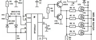
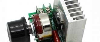
Such motors are found on electric drills, jigsaws and other tools. To reduce or increase the speed, it is enough, as in previous cases, to change the supply voltage. There are also solutions for this purpose. The structure connects directly to the network. The adjusting element is a triac, which is controlled by a dinistor. The triac is placed on the heat sink, the maximum load power is 600 W.
How to make it yourself?
There are various options for adjustment schemes. Let us present one of them in more detail.
Here is how it works:
Initially, this device was developed to adjust the commutator motor in electric vehicles. We were talking about one where the supply voltage is 24 V, but this design is also applicable to other engines.
The weak point of the circuit, which was identified during testing of its operation, is its poor suitability at very high current values. This is due to some slowdown in the operation of the transistor elements of the circuit.
SPC pulleys drawings and dimensions
The speed of rotation of the pulley = the speed of rotation of the shaft on which this pulley is fixed, the transmitted power (with a belt drive) can be considered equal to 95% of the nominal value, the pre-transmission ratios, respectively, and the rotation speeds are considered as the ratio of the diameters of the pulleys used. The moment is an inverse proportion. All these are approximate calculations, but if you need exact calculations, then download the program and calculate.
Everything is simple - this is replacing a chain drive with a belt drive, from the initial data we need the gear ratio, power and torque on the shafts, the center distance, then we drive all this happiness here and that’s it.
Works with timing belts, V-belts, multi-ribbed belts and pulleys. Accurately calculates the ratio of pulleys and belts.
We recommend. And finally, screenshots of the program! For example, click on any screen and see what it can do.
A little theory about the design and scope of commutator electric motors
Electric motors of this type can be direct or alternating current, with series, parallel or mixed excitation (for alternating current only the first two types of excitation are used).
A commutator motor consists of a rotor, stator, commutator and brushes. The current in the circuit passing through the stator and rotor windings connected in a certain way creates a magnetic field that causes the latter to rotate. Voltage is transmitted to the rotor using brushes made of a soft electrically conductive material, most often graphite or a copper-graphite mixture. If you change the direction of the current in the rotor or stator, the shaft will begin to rotate in the other direction, and this is always done with the rotor leads, so that the magnetization reversal of the cores does not occur.
If the connection of both the rotor and stator is changed simultaneously, reversal will not occur. There are also three-phase commutator motors, but that's a completely different story.
DC motors with parallel excitation
The field winding (stator) in a parallel-wound motor consists of a large number of turns of thin wire and is connected in parallel to the rotor, the winding resistance of which is much lower. Therefore, to reduce the current when starting electric motors with a power of more than 1 kW, a starting rheostat is included in the rotor circuit. The electric motor speed control with this connection scheme is carried out by changing the current only in the stator circuit, because The method of reducing the voltage at the terminals is very uneconomical and requires the use of a high-power regulator.
If the load is small, then if the stator winding accidentally breaks when using such a circuit, the rotation speed will exceed the maximum permissible and the electric motor may go into overdrive.
Series-wound DC motors
The field winding of such an electric motor has a small number of turns of thick wire, and when it is connected in series to the armature circuit, the current in the entire circuit will be the same. Electric motors of this type are more durable under overloads and therefore are most often found in household devices.
Adjusting the speed of a DC electric motor with a series-connected stator winding can be done in two ways:
AC commutator motors
These single-phase motors have lower efficiency than DC motors, but due to their ease of manufacture and control circuits, they are most widely used in household appliances and power tools. They can be called “universal”, because They are capable of operating with both alternating and direct current. This is due to the fact that when an alternating voltage is connected to the network, the direction of the magnetic field and current will change in the stator and rotor simultaneously, without causing a change in the direction of rotation. The reversal of such devices is carried out by reversing the polarity of the ends of the rotor.
To improve performance in powerful (industrial) AC commutator motors, additional poles and compensation windings are used. There are no such devices in the engines of household appliances.
In the anchor chain
This is the best option for regulating the speed of a motor with independent excitation.
The rotation speed is directly proportional to the voltage supplied to the armature. The mechanical characteristics do not change their angle of inclination, but move parallel to each other. To implement this scheme, you need to connect the armature circuit to a voltage source that can be changed.
This is possible in low or medium power electric machines. It is advisable to connect a high-power motor to a circuit with an independent excitation voltage generator.
A conventional three-phase asynchronous machine is used as a drive for the generator. To reduce the speed, it is enough to lower the voltage at the armature. It varies from nominal and down. This circuit is called “motor-generator”. This way you can change the parameters on a 220V engine.
For low voltage
Controlling 12V units is easier due to the lower voltage and, as a result, more accessible parts. There are many options for such schemes, so it is important to understand the principle itself.
Such a motor has a rotor, a brush mechanism and magnets. It has only two wires at the output; speed is controlled through them. The power supply can be 12, 24, 36V, or other. What is needed is to change it. It's better when it ranges from zero to maximum. In simpler options, 12–0V will not work; other options provide this opportunity.
Some solder radioelements using surface mounting, others assemble a printed circuit board - it depends on the desires and capabilities of each person.
This option is suitable if accuracy is not important: for example, a fan. The voltage varies from 0 to 12 volts, and the torque changes proportionally.
Another option is with stabilization of speed regardless of the load on the shaft.
The power supply is 12 volts, the circuit is very simple. The engine picks up speed smoothly and also smoothly reduces it as the output voltage varies within 12–0V. As a result, the torque can be reduced to almost zero. If the potentiometer is turned in the opposite direction, the motor also gradually gains speed to maximum. The microcircuit is very common, its characteristics are also described in detail. Power supply 12–18c.
There is another option, only this is not for 12, but for 24V power supply.
The motor is DC, the power supply is AC, as there is a diode bridge. If desired, you can throw away the bridge and power it with constant voltage from your power supply.