The grinder is a fairly popular tool that has extensive functionality. Most often they are used for cutting metal products. However, they are also suitable for working with other materials. It is worth noting that while using this power tool you will have to periodically change the rotation speed of the wheel. Therefore, it is recommended to figure out in advance how to reduce the speed on an angle grinder.
A grinder is a tool that is often used for cutting metal structures
How to connect a regulator to an angle grinder
To connect a homemade power regulator, no special knowledge is required, and any home craftsman can cope with this task.
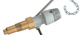
The module is installed in the gap of one wire, through which power goes to the angle grinder. That is, one wire remains intact, and a regulator is soldered into the gap of the second. If there is very little space in the grinder, then the regulator can be placed outside the tool, as shown in the following photo.
Also, the regulator can be placed in a socket and used to reduce the speed not only of an angle grinder, but also of other electrical appliances (drill, sharpener, wood milling or lathe, etc.). This is done as follows.
- Purchase a junction box from an electrical goods store (suitable with dimensions 65x65x50 mm).
- You should also buy a small outdoor socket and a power cable with an electrical plug.
- Drill a hole in the side wall of the junction box to insert a variable resistor regulator into it.
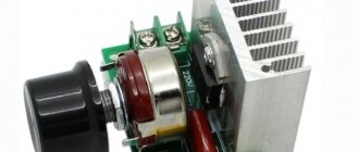
- The factory regulator board or a homemade device is placed inside the junction box. All protruding parts in the box that interfere with installation can be cut off.
- The socket should be secured to the cover of the distribution box, having first pulled the wires inside the latter.
- In the figure above you can see that the wires of the network cable touch the radiator, which heats up during operation. That's why it's wearing a PVC tube. But it’s better if you drill a hole for the network cable in a different place to prevent it from coming into contact with the radiator.
The following photos show what a finished socket will look like, having a built-in speed controller for an angle grinder, which can also be used for other electrical appliances.
Instead of a junction box, you can use any plastic case of a suitable size. You can also make the box yourself by gluing pieces of plastic together with a glue gun.
What it is?
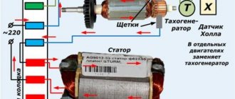
Grinders with a speed controller use commutator motors with sequential excitation.
They can operate on direct or alternating current. This type of motor is easily controlled by changing the current in the circuit. Due to the fact that modern regulators use key pulse control, they heat up very little and can be built into the body of even a small-sized instrument. For regulation, a potentiometer is used, the handle of which is located on the handle of the machine.
Why control the speed of the disk?
Different cutting or grinding speeds are required according to the physical properties of the materials being worked with. Thus, high speed with low pressure is required when cutting hard materials that might otherwise crumble or splinter. Soft materials that are not resistant to heat (thermoplastics, wood), on the contrary, require low speed:
- ceramics: 10000 rpm;
- metal: 8000 rpm;
- hard plastics: 5000 – 8000 rpm;
- wood: 3000 – 5000 rpm;
- soft plastics: less than 2000 rpm.
All professional tools are equipped with a stabilized speed controller, but inexpensive household angle grinders with a power of less than 1200 W are not always supplemented with it. In this article we will talk about how to make such a regulator yourself to reduce the speed.
Starters for angle grinders with a 20 A triac
Devices with 20 A triacs are suitable for professional grinders. Many models use contactor resistors. First of all, they are able to operate at high frequencies. The maximum temperature of the starters is 55 degrees. Most models have a well-protected case. The standard device circuit involves the use of three contactors with a capacity of 30 pF or more. Experts say that the devices stand out for their conductivity.
The minimum frequency for starters is 35 Hz. They are capable of operating in a DC network. Modifications are connected via adapters. Such devices are well suited for 200 W motors. Filters are quite often installed with triodes. Their sensitivity indicator is no more than 300 mV. Quite often there are wired comparators with a protection system. If we consider imported models, they have an integrated converter that is installed with insulators. Current conductivity is ensured at around 5 microns. With a resistance of 40 Ohms, the model is capable of stably maintaining high speeds.
Device, electrical circuit of an angle grinder with a rotation speed controller
The factory speed controller is located inside the angle grinder body and is built into the electrical circuit as follows:
Regulator connection diagram. Source here
The connection diagram is quite simple: the red wire is connected to one of the contacts of the switch, the blue wire is connected through the second contact of the starting device to one of the two stator windings, and the black wire is directly connected to the other winding.
When connecting a regulator, made by yourself or ready-made, purchased in a store, to an angle grinder where it is not provided by the manufacturer, it is not always possible to fit it inside the case. Practice shows examples of implementing a regulator as a separate unit into a network cable break. Users perform it in the form of a mobile universal device, which is applicable for other types of power tools (drill, hammer drill).
Other functions: soft start and more
Angle grinder (grinder) MAKITA 9565CVK with soft start and speed control. Photo 220Volt
In addition to the speed control device and electronic stabilization, which increase the range of work performed, the angle grinder can be equipped with other useful options.
- The soft starter allows you to reduce additional effort on the part of the user, since dynamic loads arising from a sharp increase in spindle speed greatly contribute to this. Installing a soft start is especially important for powerful angle grinders with large inertial mass. Increasing comfort during work, reducing the risk of injury, increasing the reliability of components and parts is ensured by this option.
- The automatic balancing mechanism reduces vibration and runout that occurs due to uneven wear of the working tool.
- Anti-jamming protection, which cuts off the current supply to the windings of the angle grinder during an unexpected forced stop of the electric drive. Prevents motor overheating and failure.
- In order to reduce injuries, for example, in the event of a sudden power outage, then the same unexpected switching on, restart protection is installed. After shutdown, the grinder will re-enter operating mode only after the user presses the protection lock.
- If the nature of the work does not allow you to wait a long time for the rotating spindle to stop, then an additional braking option will help stop it as quickly as possible.
- Problems that arise when replacing a working tool, even when using a special wrench, are solved by using a special quick-release nut. It allows you to change equipment in the shortest possible time.
Device Instruction Manual
The basic rule when operating an angle grinder with a homemade speed controller is to adhere to the work and rest schedule. The fact is that an engine operating at a “regulated” voltage gets especially hot. When grinding at low speeds, it is important to take frequent breaks so that the commutator windings do not burn out.
It is also highly recommended not to turn on the tool if the speed controller is set to minimum - the reduced voltage will not be enough to rotate the rotor, the collector lamellas will remain in short circuit mode, and the windings will begin to overheat. Unscrew the variable resistor to the maximum, then, turning on the angle grinder, reduce the speed to the desired value.
Following the correct order of activation and adjustment will allow you to operate the angle grinder for an unlimited period of time.
In addition, it should be understood that adjusting the speed of rotation on an angle grinder occurs on the principle of a water tap. The device does not increase the number of revolutions, it can only decrease them. It follows from this that if the maximum nameplate speed is 3000 rpm, then when a speed controller is connected, the angle grinder will operate in a range lower than the maximum speed.
Attention! If the angle grinder already contains electronic circuits, for example, it is already equipped with a speed controller, then the thyristor controller will not work. The internal circuits of the device simply will not turn on.
Video: homemade angle grinder speed controller
Equipping the angle grinder with a circuit for adjusting engine speed will increase the efficiency of using the device. and expand its functional range. This will also save the technological resource of the grinding machine and increase its service life.
Manufacturing a soft start socket
The most important requirement for such an outlet is its mobility. Therefore, you will need a carrier.
With its help, you can smoothly launch the tool anywhere - in the garage, at the dacha, during the construction of your house in different areas of the construction site.
The first step is to disassemble the carrier.
The main power wires in it can be either soldered or connected to screw terminals.
Depending on this, your additional outlet will also be connected. This should be an additional socket near the carrying case in order to be able to simultaneously connect the instrument in different modes.
By the way, if you mistakenly turn on an angle grinder or circular saw that has a factory built-in soft start into an outlet that is also equipped with such a soft starter, then surprisingly everything will work. The only thing is that there will be a delay in starting the saw or turning the disk for a couple of seconds, which is not very convenient to use and can be puzzling if you don’t get used to it.
Here are real tests of such a connection, carried out by one master from YouTube BaRmAgLoT777. His comment after such tests on a Dremel type engraver, a Bosch drill, a Makita router, and an Interskol circular saw:
Next, to assemble the socket, take a stranded copper wire with a cross-section of 2.5 mm2 and strip its ends.
Then you need to tin the contact pad on the carrier where this wire will be soldered.
Securely solder the cable cores to these pads.
Carefully lay out the wires and close the extension cord.
Take a square external socket for installation on the outer surface of the walls, and try on a soft starter unit in its housing. Since it has compact rectangular dimensions, it should fit there without any problems.
Mount and secure the socket body on the same platform as the extension cord.
The PP block is connected to the gap of any wire, phase or neutral. Do not confuse it, phase and zero are not supplied to it at the same time, i.e. 220V.
It is installed on one of the wires.
Also for this BPP, there is no difference on which side to make the entrance and on which side to make the exit. The twists are soldered and insulated with heat shrink.
After that, all the insides of the socket are assembled into a housing and all that remains is to close the entire structure with a lid.
At this point, the entire reworking of the carrying case and the manufacture of the socket can be considered complete. It will take you no more than 15 minutes.
How to make a soft start circuit for an angle grinder with your own hands
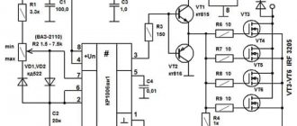
The popular circuit is implemented on the basis of the KR118PM1 phase control control microcircuit, and the power part is made of triacs. Such a device is quite easy to install, does not require additional settings after assembly, and therefore, it can be made by a master without specialized education, just be able to hold a soldering iron in his hands.
Electrical circuit for adjusting soft start for an angle grinder
The proposed unit can be connected to any power tool designed for an alternating voltage of 220 volts. A separate remote power button is not required; the modified power tool is turned on with a standard key. The circuit can be installed either inside the body of the angle grinder or in the break of the power cable in a separate case.
The most practical thing is to connect the soft starter to the socket from which the power tool is powered. The input (XP1 connector) is supplied with power from a 220 volt network. A consumable socket is connected to the output (connector XS1), into which the angle grinder plug is plugged.
When the start button of the angle grinder is closed, voltage is supplied to the DA1 chip via the common power circuit. There is a smooth increase in voltage across the control capacitor. As it charges, it reaches a working value. Due to this, the thyristors in the microcircuit do not open immediately, but with a delay, the time of which is determined by the charge of the capacitor. Triac VS1, controlled by thyristors, opens with the same pause.
Watch the video with a detailed explanation of how to do it and what scheme to use
In each half-cycle of alternating voltage, the delay decreases in an arithmetic progression, as a result of which the voltage at the input to the power tool gradually increases. This effect determines the smooth start of the angle grinder engine. Consequently, the disk speed increases gradually, and the gearbox shaft does not experience inertial shock.
The time it takes for the speed to reach the operating value is determined by the capacitance of capacitor C2. The value of 47 uF ensures a smooth start in 2 seconds. With such a delay, there is no particular discomfort when starting to work with the tool, and at the same time, the power tool itself is not subject to excessive loads from a sudden start.
After turning off the angle grinder, capacitor C2 is discharged by resistor R1. At a nominal 68 kOhm, the discharge time is 3 seconds. After which the soft starter is ready for a new start cycle of the angle grinder. With a little modification, the circuit can be upgraded to an engine speed controller. To do this, resistor R1 is replaced with a variable one. By adjusting the resistance, we control the engine power by changing its speed.
Thus, in one housing it is possible to make an engine speed controller and a soft start device for a power tool.
The remaining details of the circuit work as follows:
- Resistor R2 controls the amount of current flowing through the control input of triac VS1;
- Capacitors C1 and C2 are control components of the KR118PM1 microcircuit, used in a typical switching circuit.
For simplicity and compactness of installation, resistors and capacitors are soldered directly to the legs of the microcircuit.
The VS1 triac can be anything with the following characteristics: maximum voltage up to 400 volts, minimum throughput current 25 amperes. The amount of current depends on the power of the angle grinder.
Due to the smooth start of the angle grinder, the current will not exceed the rated operating value for the selected power tool. For emergency cases, for example, a jammed angle grinder disk, a current reserve is required. Therefore, the nominal value in amperes should be doubled.
The ratings of the radio components used in the proposed electrical circuit were tested on an angle grinder with a power of 2 kW. There is a power reserve of up to 5 kW, this is due to the peculiarity of the operation of the KR118PM1 microcircuit. The scheme is working, executed many times by home craftsmen.
If you have an old angle grinder in your arsenal, don’t rush to write it off. Using a simple electrical circuit, the device can be easily upgraded by adding the function of changing the speed. Thanks to a simple regulator that you can actually assemble with your own hands in a few hours, the functionality of the device will increase significantly. By reducing the rotation speed, the grinder can be used as a grinding and sharpening machine for various types of materials. New opportunities are emerging for the use of additional attachments and accessories.
Types of faults in the electrical and mechanical parts of the drill
DIY motion sensor repair
The most common electrical problems are when the drill sparks at the brushes due to significant grinding or wear. A device with heavily worn brushes will not turn on at all. A sign of problems with the engine is the absence of signs of its activation (sound, vibration, etc.). For a drill with variable speed control, reverse and speed control may no longer function.
Mechanical faults - failure of a bearing or gear mechanism, shaft failure. They are manifested by humming, periodic stops of the device, and slow rotation. Sometimes problems arise with the chuck: difficulties in disconnecting the drill, unscrewing the chuck relative to the shaft.
DIY speed controller
The speed controller is not installed in all models of angle grinders. You can make a block for regulating the speed with your own hands or purchase a ready-made one.
Factory speed controllers for angle grinders: photo examples
Such regulators have a simple electronic circuit. Therefore, creating an analogue with your own hands will not be difficult. Let's look at what the speed controller for grinders up to 3 kW is assembled from.
PCB manufacturing
The simplest diagram is presented below.
The simplest speed controller circuit
Since the circuit is very simple, there is no point in installing a computer program for processing electrical circuits just because of it. Moreover, special paper is needed for printing. And not everyone has a laser printer. Therefore, we will take the simplest route of manufacturing a printed circuit board.
Take a piece of PCB. Cut to the size required for the chip. Sand the surface and degrease. Take a laser disc marker and draw a diagram on the PCB. To avoid mistakes, draw with a pencil first. Next, we start etching. You can buy ferric chloride, but the sink is difficult to clean after it. If you accidentally drop it on your clothes, it will leave stains that cannot be completely removed. Therefore, we will use a safe and cheap method. Prepare a plastic container for the solution. Pour in 100 ml hydrogen peroxide. Add half a tablespoon of salt and a packet of citric acid up to 50 g. The solution is made without water. You can experiment with proportions. And always make a fresh solution. All copper should be removed. This takes about an hour. Rinse the board under running water. Drill the holes.
It can be made even simpler. Draw a diagram on paper. Glue it with tape to the cut out PCB and drill holes. And only after that draw the circuit with a marker on the board and etch it.
Wipe the board with alcohol - rosin flux or a regular solution of rosin in isopropyl alcohol. Take some solder and tin the tracks.
Installation of electronic components (with photo)
Prepare everything you need to mount the board:
- Solder spool.
Solder reel
Pins to the board
100 nF capacitor
Fixed resistor 2 kOhm
500 kOhm variable resistor
Cut off four pins and solder them onto the board. Then install the dinistor and all other parts except the variable resistor. Solder the triac last. Take a needle and brush. Clean the gaps between the tracks to remove any possible shorts. The triac with its free end with a hole is attached to an aluminum radiator for cooling. Use fine sandpaper to clean the area where the element is attached. Take heat-conducting paste of the KPT-8 brand and apply a small amount of paste to the radiator. Secure the triac with a screw and nut. Since all the parts of our design are under mains voltage, we will use a handle made of insulating material for adjustment. Put it on a variable resistor. Use a piece of wire to connect the outer and middle terminals of the resistor. Now solder two wires to the outer terminals. Solder the opposite ends of the wires to the corresponding pins on the board.
You can make the entire installation hinged. To do this, we solder the parts of the microcircuit to each other directly using the legs of the elements themselves and the wires. Here you also need a radiator for the triac. It can be made from a small piece of aluminum. Such a regulator will take up very little space and can be placed in the body of the angle grinder.
If you want to install an LED indicator in the speed controller, then use a different circuit.
Regulator circuit with LED indicator.
Regulator circuit with LED indicator
Diodes added here:
- VD 1 - diode 1N4148;
- VD 2 - LED (operation indication).
Assembled regulator with LED.
Assembled regulator with LED
This unit is designed for low-power angle grinders, so the triac is not installed on the radiator. But if you use it in a powerful tool, then do not forget about the aluminum board for heat dissipation and the bta16 triac.
Electronic unit testing
Before connecting the unit to the instrument, let's test it. Take the overhead socket. Install two wires into it. Connect one of them to the board, and the second to the network cable. The cable has one more wire left. Connect it to the network card. It turns out that the regulator is connected in series to the load power circuit. Connect a lamp to the circuit and check the operation of the device.
The speed controller is connected to the tool in series.
How to disassemble an angle grinder
How to disassemble an angle grinder? It's not such a complicated process. This does not require special knowledge, but everything must be done carefully and with caution. Every owner needs to know how to disassemble any working tool, because periodically it needs internal cleaning from dirt and dust, and its service life depends on this.
Nowadays on the market you can choose different types of grinders, which differ in operating parameters, size, and quality. Manufacturers are also different. Whatever model of grinding machine you buy, they all have the same model for assembling parts.
Disassembling the angle grinder will require few tools; you just need a regular screwdriver or a reversible one with a ratchet mechanism.
Having prepared the screwdriver, you can start disassembling:
- We unscrew the screws from the body and remove one side of the product.
- Remove the nut that holds the disk in place and unscrew the bolts securing the protective casing.
- Remove the brushes.
- Disconnect the wires from the engine.
- We unscrew the bolts that secure the gearbox inside and very carefully remove it; the rotor is also removed with it.
- We unscrew the bolts that hold the stator and remove it.
- We assemble the angle grinder back, put everything in place one by one in reverse order and screw it on.
When disassembling an angle grinder, it is important to remember the order in which parts are removed in order to assemble it correctly.
Power speed regulator
Work principles
With its help, the electrical device operates at the set engine speed and does not reduce it. The engine speed controller also affects the cooling and ventilation of the motor. With the help of power, the speed is set, which can be either raised or reduced.
Many people have asked the question of how to reduce the speed of a 220 V electric motor. But this procedure is quite simple. One has only to change the frequency of the supply voltage, which will significantly reduce the performance of the motor shaft. You can also change the power supply to the motor by activating its coils. Electrical control is closely related to the magnetic field and motor slip. For such actions, they mainly use an autotransformer and household regulators, which reduce the speed of this mechanism. But it is also worth remembering that engine power will decrease.
Shaft rotation
Engines are divided into:
- asynchronous,
- collector
The speed controller of an asynchronous electric motor depends on the current connection to the mechanism. The essence of the operation of an asynchronous motor depends on the magnetic coils through which the frame passes. It rotates on sliding contacts. And when, when turning, it turns 180 degrees, then through these contacts the connection will flow in the opposite direction. This way the rotation will remain the same. But with this action the desired effect will not be obtained. It will come into force after a couple of dozen frames of this type are added to the mechanism.
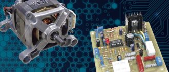
The washing machine motor also needs power adjustment. For this purpose, special boards were made that cope with their job: the engine speed control board from a washing machine has multifunctional use, since its use reduces the voltage, but does not lose rotation power.
The circuit of this board has been verified. All you have to do is install diode bridges and select an optocoupler for the LED. In this case, you still need to put a triac on the radiator. Basically, engine adjustment starts at 1000 rpm.
If you are not satisfied with the power regulator and its functionality is lacking, you can make or improve the mechanism. To do this, you need to take into account the current strength, which should not exceed 70 A, and heat transfer during use. Therefore, an ammeter can be installed to adjust the circuit. The frequency will be small and will be determined by capacitor C2.
Next, you should configure the regulator and its frequency. When outputting, this pulse will go out through a push-pull amplifier using transistors. You can also make 2 resistors that will serve as an output for the computer's cooling system. To prevent the circuit from burning out, a special blocker is required, which will serve as double the current value. So this mechanism will work for a long time and in the required volume. Power regulating devices will provide your electrical appliances with many years of service without special costs.
Design features of the Makita angle grinder
Before it completely breaks down, the grinder usually starts giving distress signals. Diagnosis is best carried out according to the principle from simple to complex. In addition, damage to the magnetic circuit and commutator can cause failure. The lifespan of these devices is usually limited to several years; of course, it all depends on the intensity of use. How to make repairs If the angle grinder does not start when the start button is turned on, then there is reason to believe that the reason here is not so serious, and it is not difficult to carry out repair work yourself. Remove the nut, take out the flat washer pos. Synthetic fabrics can catch fire or be damaged by burning.
Repairs can be done at home. It is one of the parts of the engine with an armature located inside.
Pieces of material being ground may have a high temperature. User reviews confirm the well-deserved popularity of the tool both among craftsmen who professionally use this angle grinder in production, and among amateurs who like to tinker at home.
If unsuccessful, the existing solder must be replaced. This part is located inside the electric motor and begins to rotate during operation.
In this case, both the rotation speed of the working disk and the power it develops are subject to adjustment; The stator is the part of the electric motor of the angle grinder in which the armature and rotor rotates. grinder repair
Making a speed controller
An electric angle grinder is impossible without a speed controller, so that it is possible to reduce the speed.
The regulator circuit from a physics point of view looks like this
- Resistor – R1;
- Trimmer resistor – VR1;
- Capacitor – C10;
- Triac - DIAC;
- Triac - TRIAC.
The electronic regulator can be not only built-in, but also remote for convenience. In Bosch angle grinders, the electronics set the speed from almost 3 thousand to 11.5 thousand. There is no load on the meter's power, all indicators are taken into account. Reducing the number of revolutions and increasing them is not difficult for the tool. Adjustable rotation speeds are simply necessary when working with an angle grinder.
Usage
There are a number of recommendations for the correct use of an angle grinder with an electronic unit. When starting the tool, let it accelerate to the set speed, do not rush to cut anything. After turning off, restart it after a few seconds so that the capacitors in the circuit have time to discharge, then the restart will be smooth. You can adjust the speed while the grinder is operating by slowly turning the variable resistor knob.
The good thing about a grinder without a speed controller is that without serious expenses you can make a universal speed controller for any power tool yourself. The electronic unit, mounted in a separate box, and not in the body of the grinding machine, can be used for a drill, drill, or circular saw. For any tool with a commutator motor. Of course, it’s more convenient when the control knob is on the instrument, and you don’t have to go anywhere or bend over to turn it. But here it’s up to you to decide. It's a matter of taste.
What is this function, principle of operation, electrical circuit, advantages of an angle grinder with a regulator
An angle grinder that is not equipped with a speed control device operates exclusively at maximum rotation speed. Equipped with this option, it allows you to reduce the rotation speed to a value that allows you to efficiently process materials, which is impossible at maximum mode.
The electronic unit of the speed controller is based on a modified dimmer principle, where the power is changed by manually changing the value of a variable resistor. With the help of electronic control of the current strength, the torque is maintained on the working shaft of the spindle, ensuring the functionality of the angle grinder. The main working elements of such a circuit can be either a semiconductor device triac or a more advanced version with an integrated circuit.
Connection diagram without power regulator
The electrical circuit of ordinary household angle grinders without additional options is shown in the figure:
Electrical diagram of an angle grinder. Photo source here
Here, two unconnected stator windings are connected to a voltage source (household network) through a switch, which has a manual start button in its design. Next, each of the windings is connected using special contacts to graphite brushes, which are pressed against the surface of the commutator using springs. In turn, the ends of the rotor windings are connected to the commutator lamellas, forming a closed electrical circuit.
The speed controller is connected to the open circuit between the on/off button and the stator windings when located inside the body of the angle grinder. If designed as a separate unit, it can often be located in a break in the network cable.
How to make adjustments for an angle grinder at home, homemade options
Some users who have experience working with electrical technologies can make relatively simple adjustment circuit However, it will not be able to effectively adjust the current strength as the speed decreases, and the amount of torque on the operating shaft may be insufficient. This will not be a big obstacle when carrying out work on polishing, cutting thin sheet metal or processing soft materials (plastic and the like).
If making a circuit with your own hands causes difficulties or the nature of work with an angle grinder, for example with stone or ceramics, requires the use of a more complex system with a microcircuit , it is possible to purchase a ready-made block and install it on an angle grinder.
The authors of the videos presented below offer their approaches to the decision to equip an angle grinder with speed control.
A standard dimmer for changing the brightness of lighting is used in the operation of an angle grinder in the following video.
Important: the power of the dimmer must be at least not less than the power of the angle grinder. The quality of polishing work and the smaller amount of dust emitted during it determine the feasibility of modifying the electrical part of the angle grinder using a standard dimmer. This design requires a reasonable dosage of manual load when carrying out work, since overheating of the engine cannot be ruled out and there is a risk of its failure.
A ready-made semiconductor power regulator can be purchased in online stores. The author of the following video purchased a Chinese copy from Aliexpress, and it has quite a lot of power - 4 kW. This value makes it possible to increase the versatility of its application. Many household appliances (grinder, drill, heating elements in the form of heating elements) are operated in power ranges where such a regulator can work quite effectively. The main disadvantage of such regulators is the inability to maintain the load for a long time (the power tool quickly overheats and needs to be stopped to cool down).
The speed of some electric tools can be controlled not only manually using a rotary wheel. Some devices are more convenient to control using pedals . In the following video, the author demonstrates this method of control. Here, a speed controller made in the form of a pedal from a sewing machine is taken and adapted to control an electric jigsaw. There is nothing stopping you from making this option for controlling the angle grinder, but the need for this must be justified by the nature of the work being carried out.
No power loss
It is almost impossible to make a regulator that changes speed without losing power . Such devices with feedback for monitoring the speed value and adjusting the current strength based on them are produced only by manufacturers of angle grinders. You can only make or install regulators on semiconductor circuits , which do not guarantee 100% power conservation when changing the rotation speed of the angle grinder spindle.
How to reduce/increase disk rotation speed
A ready-made inexpensive Chinese-made board can be mounted , as the author of the following video did, in a separate plastic case connected to a cable with a plug and a socket installed on it. By connecting the plug to the electrical network, and the angle grinder to it through the socket, you can change the value of the variable resistance with the adjusting wheel and set the required speed on the angle grinder. Surface polishing with such a power tool will be much better.
How to install, connect
Users of grinders have come up with many different ways to arrange the speed controller and the grinder for which it is intended. It can be located as a stand-alone element outside the body of the angle grinder, or built inside . Below are videos with these options.
In the following video, the author uses a carrying device with an on/off button . Just instead of this very button, a ready-made Chinese semiconductor board is inserted. The technology of electrical installation work was performed at a good technical level. This type of carrier will be convenient to use when using an angle grinder for work that requires the use of low speeds.
Placing additional devices inside the body of an angle grinder can be quite a difficult problem. Often non-trivial decisions , as, for example, in the following video. Here, in order to place a board with speed control and soft start, we had to change the buttons involved in the operation of the on/off lever. In the freed space we managed to place a triac with a radiator for cooling the speed controller and a board with a soft-start microcircuit for the grinder.
How to disable or remove the voltage sensor
In the following video, the author’s speed controller failed on one of the angle grinder models. Attempts to repair it were unsuccessful. The author describes how you can remove a broken regulator and assemble an electrical circuit without it (just connect the stator windings directly through a switch). The grinder will function only at maximum speed.
Schematic diagram of the speed controller
Modern angle grinder speed controller circuits are built on the principle that a semiconductor switch transmits only part of the power of one or both half-waves of alternating current. Triacs (symmetrical thyristors) are used as a half-wave length regulator in such devices, which is why they are sometimes called triac regulators. The figure below shows a simplified diagram of such a device, sufficient to explain the principle of its operation, and to the right of it are diagrams of the full period of alternating current before and after regulation. Here, the shaded areas correspond to the power that is transferred to the electric motor from the power source through the triac regulator.
In the diagram, the wave symbol indicates an alternating voltage source, and the letter “M” indicates the angle grinder’s motor. In a simplified form, the regulator includes two RC circuits, a dinistor and a triac. When switch K1 is pressed, alternating voltage is supplied to the electric motor M and the regulator circuit. The current flowing through the variable resistor R1 begins to charge the capacitor C1. Its charging time is determined by the resistance of resistor R1, which depends on the position of its motor, which, in fact, sets the time parameters of the regulator’s operation. After the capacitor is fully charged, the voltage at the point of its connection to the dinistor increases to the nominal value, the dinistor opens and supplies voltage to the control electrode of the triac. Capacitor C1 is discharged. This moment is shown in the diagram of the regulator operation by a thick vertical line. After the triac opens, voltage is supplied to the grinder motor in the first half-cycle.
When the polarity of the alternating current changes, the voltage passes through zero, so the dinistor and triac are closed. In the negative half-cycle, everything is repeated, and the triac is turned on with a delay determined by the parameters of the R1C1 chain. The regulator, even at idle, operates with some delay in turning on the triac. This is due to the fact that, although the moment the current is supplied by resistance R1 to capacitor C1 corresponds to the voltage crossing zero, it must still rise to the level of the breakdown voltage of the dinistor. The figure below shows the dependence of the power supplied to the angle grinder engine on the time shifts of the dinistor control pulses. In the first case, the resistance of resistor R1 is minimal, so C1 charges quickly, and in the second case, it is maximum, so the capacitor charges more slowly.
Advantages of universal angle grinders
Angle grinder (grinder) METABO WEV 10-125 Quick 600388000 (in box). Photo 220Volt
It is not always possible to solve the problem of processing certain types of materials with an ordinary angle grinder without additional options; the working tool is not suitable for effective work at the speeds produced by an angle grinder without a speed controller. The problem of choosing the right modes is especially acute for users involved in grinding, cleaning, and polishing various materials. To complete the job, sometimes you have to look for another tool with suitable characteristics.
The versatility of angle grinders with variable speed control lies precisely in the ability to independently set the rotation speed of, for example, cord brushes when stripping. When performing grinding operations, the contact patch between the working tool and the surface being processed increases, which requires the use of high-power grinders. Such grinders with additional options installed on them perform almost any type of work with various materials.
How to make a speed controller with your own hands + (Video)
In order not to complicate the perception of the operating principle with complex terms, the fundamental operation of the circuit can be explained simply. It has a sensitive element that reads the load value. Depending on the read value, this element controls the locking device.
The operating principle is similar to that of a water tap. In this case, you are the sensing element that controls the water tap. The flow of water, depending on the need, becomes more or less. The same process occurs with current.
It is necessary to correctly understand the point that we cannot in any way increase the rotation speed beyond that indicated in the characteristics of the angle grinder. We can only lower the speed. If the maximum rpm is 3000, then the range in which we can adjust the rpm will be below this value.
In the simplest version, you can use a thyristor regulator circuit. He will both feel and regulate. Two in one. This circuit has only five parts. It is very compact and easily fits into the case. Such a regulator will not operate from zero speed, but this is not necessary for an angle grinder.
If lower speeds are needed in operation, then it is necessary to use another circuit on an integrated circuit, where the locking element will be a triac. Such a circuit will be able to regulate the speed from almost zero to the desired value.
In both schemes, the main load falls on the locking element. It must be designed for voltages up to 600 V and currents up to 12 A. If your grinder is more powerful than 1 kW, then the locking element must withstand a load of up to 20 A.
All parts of the thyristor circuit can be placed on a printed circuit board or simply mounted. According to the second option, the parts are soldered on a printed circuit board. A printed circuit board can be manufactured using different methods. It can be etched from foil PCB, you can even cut it out with a cutter, but it will turn out very roughly. In principle, you can ask a radio amateur you know to make it for a very modest reward.
Radio-electronic elements are inserted into the manufactured printed circuit board. They can be purchased in specialized stores or at radio markets. The ratings of each should not differ in rating and rated power. It is advisable to install a thyristor or triac on a heat sink - an aluminum or copper radiator.
When the finished board is ready, you need to choose a convenient place in the grinder body to install it. It is advisable to install it so that it is convenient to use and so that it does not interfere with the work process.
Before installing the circuit in the car, it must be checked. To do this, instead of an angle grinder, you need to connect a regular incandescent lamp to the output. An example with a power of 60 - 40 W at 220 V is suitable. The performance will be obvious by the change in the glow of the light bulb.
Now all that remains is to mount the device in the chosen location and perform a test run of the angle grinder. It will stop breaking out of your hands during startup, and the speed will be smoothly adjusted by rotating the regulator.
Bulgarian and its operation
An angle grinder is called an angle grinder. The name of the instrument is due to the fact that it was produced in Plovdiv. It is intended for performing work on grinding or trimming hard material:
Does a good job of sharpening tools.
A grinder is a very necessary tool these days, so almost everyone has one.
There are grinding machines of different power: from 500 W to 2500, depending on the thickness of the wheel - from 115 mm to 230 mm. The most popular ones in use are angle grinders with a power of 1.2 W, and the most used disc is 125 mm thick.
Every year the choice for this construction power tool becomes wider, but the operating rules remain almost unchanged. And even if you always adhere to them, sooner or later malfunctions arise in the mechanism, which you can try to fix yourself by collecting everything you need to repair the angle grinder.
What is rotation speed adjustment, how does it work, is it needed and why?
In the simplest version, the rotation speed can be changed using a power control device, which is based on the principle of variable resistance. That is, by and large it is an ordinary rheostat. Many users use it on household grinders when carrying out polishing and grinding work with soft materials, where at low speeds they can achieve high-quality results.
Typical electrical circuit diagram of the speed controller. Photo source here
However, the use of such a device increases the risk of overheating of the angle grinder, as overloads occur at low speeds. For this reason, the feasibility of equipping household angle grinders with a power regulator is highly questionable.
Professional, powerful angle grinders are equipped with a more complex technical device for adjusting speed, which is based on an electronic circuit. The presence of a function to support rotation speed when the load changes is its distinctive feature. The prices for such grinders are much higher than for ordinary household ones.
Useful video
The system for maintaining the speed of professional angle grinders during regulation includes a sensor that reads the rotation speed. The magnet included in the sensor design sends a signal to an electronic control device, which reports data on the rotation speed. The electronic unit reacts accordingly, increasing the current in the electric drive windings as the load increases (reduces speed). This feedback from the tachometer and the electronic unit occurs continuously and maintains a stable rotation speed in different operating modes of the angle grinder.
Where can I buy
It is possible to purchase a speed controller device from employees of companies that are collected in the appropriate section. In addition, performers may be interested in angle grinders equipped with a rotation speed control function. The sale of such power tools is carried out by enterprises from a separate section.
Sections: Speed regulators for grinders, Do-it-yourself repair of grinders
Previous article: Do-it-yourself repair of revolutions of grinders Next article: Nut for grinders
For what purpose does an angle grinder have low speeds?
The integrated option for adjusting the speed of the wheel makes it possible to carefully process materials such as wood or plastic. At lower speeds, comfort and safety increase. This option is most practical in radio and electrical installations, service stations and restoration studios.
In addition, among professionals who use power tools, there is a belief that the more trivial a device is, the more reliable it is. And it is advisable to take the additional service “filling” beyond the boundaries of the grinder. With this approach, equipment maintenance is greatly simplified. In this regard, some companies deliberately produce remote individual electric regulators that connect to the network cable of an angle grinder.
Why does the grinder need low speeds?
The built-in disc speed control function allows you to delicately process materials such as plastic or wood. At low speeds, operating comfort and safety increases. This function is especially useful in electrical and radio installation practice, in car services and restoration workshops.
In addition, among professional users of power tools there is a strong opinion that the simpler the device is, the more reliable it is. And it is better to move the additional service stuffing outside the power unit. In this situation, equipment repair is greatly simplified. Therefore, some companies specially produce remote, separate electronic regulators that connect to the machine’s power cord.