Precision is paramount | 08/10/2016
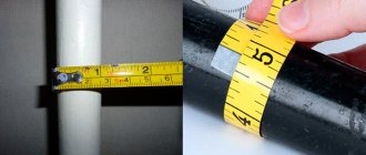
Different types of measurements require their own accuracy. Part sizes are usually measured with a micrometer. But what to do if you need to measure not the part itself, but the hole in it? Today, we will talk about a little-known tool for which it will not be difficult to give a value accurate to hundredths of millimeters for the cylinder block of your car.
What does the device measure?
Before you buy or use any measuring device, you must first find out what you can measure with it.
The main task of the bore gauge is to determine the distance from one surface to another inside the groove. The device is especially popular when it is necessary to take measurements in places where it is impossible to reach with a caliper. Measurements of internal dimensions can be performed with a regular ruler, for which you need to attach it to the walls of the object being measured and take readings. However, such a tool is not effective when it is necessary to obtain high-precision values, which are very important in technology. Fractions of millimeters play a very important role, so a tool called a bore gauge was developed specifically for measuring the dimensions of internal cavities.
With its help, two types of measurements are performed - absolute and relative methods. To determine absolute values, a micrometric bore gauge is used. The principle of its operation is similar to a micrometer. The instrument must first be placed inside the hole, and then readings must be taken. The device allows you to obtain absolute values in millimeters.
The relative method involves the use of an indicator bore gauge (different in design from a micrometric one), which must first be moved to the working position. With its help, the size is not determined, but the deviation along the entire length of the surface is detected.
The device measures the following parameters of the part:
- diameter of holes of round, square, oval and other types of sections;
- groove width;
- distances in complex shaped parts.
The devices are simply indispensable tools for lathes and millers who turn various metal parts by hand. The device is used in workshops for repairing internal combustion engines and other mechanisms and components.
Telescopic shtihmas
The device of the telescopic stichmas is similar to that of a micrometer. Measurement accuracy – 0.01 mm. Designed to check horizontal and vertical surfaces, ovality, taper of shafts, holes and cylinders.
The measuring parts of the gauge are made from the following types of steel:
- cemented carbon steels 15 and 20 (Cemented steels are used for the manufacture of wear parts and are exposed to variable and shock loads);
- carbon 12A;
- ball bearing ШХ15;
- instrumental alloyed X and CH.
To ensure that the measuring surfaces are preserved as long as possible, they are chrome-plated, nitrided or overlaid with a durable alloy.
What happens to the clearance between the piston and cylinder
During proper operation of the engine, a natural process occurs and the gap between the piston and cylinder narrows. This occurs based on the conditions of constant operation in high temperature conditions of parts.
In addition, the reason for the narrowing of the gap between the piston and the cylinder may be improper adjustment of moving parts, temperature overload or misalignment of the cylinders. It should not be forgotten that cylinder blocks are increasingly made of aluminum materials, which have double the expansion coefficient compared to alloy cast iron.
The reduced clearance between the piston and cylinder leads to semi-dry friction and, as a result, the temperature of the cylinder block parts increases. Gradually, lubrication stops altogether and the disappearance of the gap results in the first scuff marks on the piston.
Almost always, the result of diagnosing the condition of the cylinder block is the repair of the cylinders and elements of the engine piston group. It is possible to fully determine the extent of defects in pistons, liners and other parts only after disassembling the cylinder head.
Having reached the piston group, we begin to troubleshoot the cylinders and pistons. The main measuring instruments for measuring diameters are: a micrometer - for pistons and a bore gauge (indicating gauge) for measuring the diameter of the cylinder.
How to measure piston ring clearance
At the first stage, you just need to visually inspect the part. It should not have cracks or any other defects. If you notice even minor mechanical damage, the element must be replaced with a new one.
Some preventive procedures will also help
The piston head must be cleaned of carbon deposits, and special attention must be paid to the grooves that are located under the rings. Only after these procedures can you begin to inspect the gap
Since there are only three rings in the device. Each has its own parameters:
- Upper compression 1-0.04-0.075 mm.
- Lower compression 2-0.03-0.065 mm.
- Oil scraper 3-0.02-0.055 mm.
Be extremely careful when taking measurements. Each ring has its own optimal gap size. For greater accuracy, use a micrometer. This is a device that allows you to measure all the parameters you need with extreme accuracy. For this purpose, there are special probes that allow you to easily and quickly take readings from the grooves.
What is a bore gauge and its purpose?
Another name for a measuring instrument, which is equivalent to a caliper and a micrometer, sounds like shtihmas. Its advantage is the ability to carry out measurements with high accuracy up to 0.01 mm, and the error does not exceed 0.006 mm.
High accuracy of internal diameter measurements is needed not only in the manufacturing industry. The tool is used by jewelers engaged in the production of jewelry, shoe repair specialists, specialists in the repair of internal combustion engines, etc. Unlike a radius gauge, a bore gauge is capable of determining internal distances in hard-to-reach places (in recesses).
The device is used in the following cases:
- In the manufacture of parts with internal cavities.
- To determine the degree of wear, for example, on the walls of internal combustion engine cylinders.
- Checking the compliance of actual sizes with those declared by the manufacturer.
The bore gauge allows you to check the accuracy of various devices and certify them. Before we consider the design of the shtihmas, let’s look at the types of devices.
see also
Changing the oil in the Kia Sportage 3 engine- What type of oil pump is used in internal combustion engines?
- Pressure gauge for measuring oil pressure in internal combustion engines
- Is it necessary to flush the engine when changing the oil?
How to properly check the oil level in an internal combustion engine- Changing the oil and oil filter in the internal combustion engine
- Why does the Subaru Forester shake at idle?
- Where is the engine number on a Hyundai Accent?
- DVS Sura calendar of events for 2022
- Where is the engine number on a Hyundai Accent?
- For what purpose is supercharging used in an internal combustion engine?
Standards for compliance of pistons and cylinders
First of all, when you start repairing a piston group, you should know that there are groups of piston diameters, and tables of nominal sizes of cylinders and pistons. It is this information that you need to focus on in the future.
The diameter of the pistons is classified according to the outer diameter into 5 classes: A, B, C, D, E every 0.01 mm of size. Plus categories for the diameter of the hole for the piston pin every 0.004 mm. This data in the form of a number (orifice category) and a letter (piston class) is marked on the piston bottom.
There are design standards that the gap between the piston and cylinder must correspond to. For new parts it should be 0.05 - 0.07 mm. For used parts, the gap between the piston and cylinder should not exceed 0.15 mm.
Actually, this is why the gap between the piston and the cylinder is measured. To either purchase pistons of the exact same class as the cylinders. If the operating engine has a gap between the piston and cylinder exceeding 0.15 mm, then you need to begin selecting pistons for the cylinders, as close as possible to the design size.
The cylinders must first be bored as close as possible to the closest repair size. Plus, you need to remember to leave an allowance of about 0.03 mm for honing the cylinder surface after boring. But now we can go for the pistons.
When honing, it is necessary to maintain the diameter so that when installing the piston, the gap corresponds to the permissible maximum gap for new parts - 0.045 mm.
Pistons are measured with a micrometer, and cylinders with a bore gauge. The diameter of the cylinder is measured in four zones and two perpendicular planes.
When selecting pistons for cylinders, in addition to the nominal or repair size, it is necessary to take into account the weight of the pistons. It can be normal, increased or decreased by 5 grams. In addition, repair rings, also of repair sizes, are selected for the pistons of the repair group.
Having determined the gap between the piston and the cylinder, you can easily select the required dimensions, and after boring the cylinder (if necessary), install the piston.
Good luck determining the piston to cylinder clearance.
A lot of questions arose (I started to capitalize on the engine.)
- Log in to reply to this topic
#1 levka
- New opelovod
- Posts: 15
- Gender: Man
- City: KurGan
- Car: ascona C 1.6 1986 c16lz carb
Post edited by levka: 13 February 2010 - 20:54
- Top
#2 Dmitriy294
- Gender: Man
- Interests: Everything AUTO.
- Car: Commodore A
- Skype: Dmitriy294
- Real name: Dima
- Place of residence: St. Petersburg
Well, for starters, to be sure, take it to the boring men and they will tell you to sharpen it or not. And if you sharpen it, then to what size. Then you buy pistons with rings and with them back to the boring men. That will be more correct. but if the unevenness is palpable, then it is most likely to sharpen.
- Top
#3 thin
- Gender: Man
- Interests: Cars, computers
- Car: TAZ 2104i, Lada Granta Cross, AZLK 2141
- Real name: Anton
- Place of residence: Balashikha, Roissia
Best regards, tonche
- Top
#4 levka
- Gender: Man
- City: KurGan
- Car: ascona C 1.6 1986 c16lz carb
- Top
#5 thin
- Gender: Man
- Interests: Cars, computers
- Car: TAZ 2104i, Lada Granta Cross, AZLK 2141
- Real name: Anton
- Place of residence: Balashikha, Roissia
Best regards, tonche
- Top
#6 Serega
- Gender: Man
- Interests: —
- Car: there was an OPEL REKORD 2.2i automatic transmission, now there is an Omega 2.5TD automatic transmission in 1998.
- Skype: serega_ess
- Real name: Seryoga
- Place of residence: collective farm Dzerzhinsk in Belarus
- Top
#7 mantazavr
- Gender: Man
- Interests: opel manta gsi 2.0
- Car: manta b
- Real name: Nail
- Place of residence: Moscow
- Top
#8 levka
- Gender: Man
- City: KurGan
- Car: ascona C 1.6 1986 c16lz carb
- Top
#9 thin
- Gender: Man
- Interests: Cars, computers
- Car: TAZ 2104i, Lada Granta Cross, AZLK 2141
- Real name: Anton
- Place of residence: Balashikha, Roissia
Best regards, tonche
- Top
#10 mihmeh
- Gender: Man
- Car: Opel Record c coupe
- Real name: Mikhail
- Place of residence: St. Petersburg
Post edited by mikhmekh: 14 February 2010 - 21:34
- Top
#11 opelist
- Gender: Man
- Car: OPEL
- Real name: Seryoga
- Place of residence: Russia, Saratov
or what SMS 89271277465 Seryoga I will sell spare parts from these cars:
Omega A '88 C20NE Senator A1 '79 2.0S Record caravan E2 '83 C20NE Record sedan E2 '83 C20NE Senator B '88 C30NE
- Top
#12 mihmeh
- Gender: Man
- Car: Opel Record c coupe
- Real name: Mikhail
- Place of residence: St. Petersburg
Types of bore gauges
A bore gauge is a measuring device that is classified into two main types. The devices differ in the method of carrying out measuring manipulations. They are:
- Micrometric - designed to determine the exact distance in millimeters.
- Indicative ones differ in design from micrometric ones, and they are intended to determine the difference between the real size and the template size. Typically, such devices are indispensable tools for craftsmen involved in the repair and boring of internal combustion engines.
Features of sleeve technology
uses professional bore gauges that allow you to measure the internal linear dimensions of cylindrical holes with an accuracy of 0.01 mm. During the diagnostic process, our experienced technicians make a conclusion about the condition of the surfaces and the need to liner a solid-cast cylinder block or repair (replace) factory liners.
The cost and complexity of repairing piston cylinder liners depend on the design features of the engine and the type of liners used:
- replacing “wet” liners (in contact with the coolant) is a technologically simple process that can be performed manually;
- installation of “dry” liners (not in contact with the coolant) is more labor-intensive, full of various auxiliary work and must be carried out by experienced craftsmen using special equipment and chemical compounds.
Most modern internal combustion engines are equipped with “dry” liners and must be repaired by specialized specialists.
Regardless of the type of sleeve, they must be durable, resistant to high temperatures and not afraid of corrosion.
Design of a micrometric bore gauge
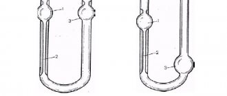
A micrometer inside gauge is designated NM, and is used to measure internal dimensions using the absolute method, that is, it allows you to find out the exact value of the distance. The components of the devices are:
- The drum is a rotating part with a vernier scale for determining readings. When the drum rotates, the rods move.
- The head is the connecting element of the drum with a removable rod and extensions.
- Locking screw or clamp - secures the device in a stationary position.
- An extension is a structural part of the device, which is used depending on the size of the part being measured.
- The tip is an important part of the measuring instrument.
The design of a micrometric bore gauge is shown in the photo above. It is worth noting that such a tool is designed for measuring distances from 50 to 2500 mm. To determine the diameter of parts ranging in size from 5 to 50 mm, devices with side jaws are used.
A bore gauge for measuring absolute values can have not only a micrometric scale for taking readings, but also an indicator one. Such devices are available in three standard sizes with a measuring range from 1250 to 10000 mm.
To designate them, the abbreviation NMI is used - internal micrometric indicator meter. Measuring instruments are supplied in wooden cases, which ensure a long service life of the instruments, protecting them from the negative effects of various factors.
Engine displacement calculator
The volume of a car engine is a constant value that does not change over the years of operation. The amount of horsepower it produces mainly depends on this value of the power unit.
Power is of key importance when taking out annual car insurance, in addition to influencing the dynamics of the vehicle's speed. To find out the desired value, they rely on torque, air flow, acceleration speed up to one hundred kilometers per hour, etc.
A car engine power calculator is an effective tool for those who want to find out how much power the engine has.
Design and device of an indicator bore gauge
Indicator bore gauges are used to measure internal distances in a relative manner. The abbreviation NI is used to designate them, and the produced models differ from each other in the measurement range. The devices consist of an extension rod with a rod inside, a dial indicator with a scale, as well as a direct working part called a tip.
In instruments of the NI-10 and NI-18 models, a wedge gear is used as a mechanism for transmitting the force of movement of the movable rod, and in instruments of the NI-50 to NI-450 brands a lever design is used. Only on the NI-700 and NI-1000 bore gauge models, transmission mechanisms are not used, since the rod is in direct contact with the reading device.
The handle of the device is made of materials with low thermal conductivity. This is necessary to ensure that heat from your hands does not affect the measurement results. Rods are working elements that are fixed to the tip depending on the distance between the walls of the part being measured.
This is interesting! Rods are usually supplied with the device, which expands its measuring capabilities. They are made from hard steel grades, which is necessary to prevent the slightest deformation during measurements. This is important to consider if you plan to make the rod yourself. There are no difficulties in this, since you need to select a suitable workpiece from hardened steel and cut a thread in it that matches the tip of the device.
There are two scales on the pointer indicator of the indicator pin. One scale is the main one (its division value is 0.001 mm), and it shows the relative deviation from the original position, and the second one serves to indicate the number of full revolutions of the main hand (one full revolution is equal to 1 mm).
Indicator-type devices are not designed to determine the exact dimensions of internal holes, but to identify the presence of deviations on the internal surface of the part along its entire length. The magnitude of their error ranges from 0.025 to 0.15 mm. Indicator bore gauges are classified into two types - mechanical or pointer and digital or electronic. Electronic devices are characterized by high accuracy and ease of use. Their main drawback is the price, which is 2 times higher than the cost of an analog device.
If it is necessary to obtain high-precision values, the NI-V device is used, which differs from classical models in the design of the measuring head. Its accuracy is 1 micron. Such tools are used specifically to make high-precision measurements of small holes.
This is interesting! The work of the relative bore gauge is to transmit the amount of force or degree of compression of the rod to the indicator pointer.
It is worth noting that there is no specific classification for the design of bore gauges. They are divided into two types - micrometric and indicator. Each type has its own subtypes, which differ in design and type of contact with the surface. They come in lever, cone, wedge, collet, ball, telescopic, with side jaws and others. In this material we will look at how to use a bore gauge (shtihmas) of the indicator and micrometric type, as well as what needs to be done before taking measurements, and what determines the accuracy of the results obtained.
Engine capacity
The formula for calculating a cylinder has been known since school curriculum - the volume is equal to the product of the area of the base and the height. And in order to calculate the engine volume of a car or motorcycle, you also need to use these multipliers. The working volume of any engine cylinder is calculated as follows: V=πr²h where,
h - piston stroke length mm in the cylinder from TDC to BDC (Top and Bottom Dead Centers)
r — piston radius mm
n - 3.14 is not a nominal number.
How to find out engine size.
To calculate the engine displacement, you will need to calculate the volume of one cylinder and then multiply by the number of cylinders in the internal combustion engine. And this is what happens:
Veng = Pi multiplied by the square of the radius (piston diameter) multiplied by the stroke height and multiplied by the number of cylinders.
Since, as a rule, piston parameters are indicated everywhere in millimeters, and engine volume is measured in cm3, then to convert the units of measurement, the result will have to be divided by another 1000.
Note that the full volume and the working volume are different, since the piston has bulges and recesses for the valves and also includes the volume of the combustion chamber. Therefore, you should not confuse these two concepts. And to calculate the real (total) volume of the cylinder, you need to sum up the volume of the chamber and the working volume.
You can determine the engine volume using a regular calculator, knowing the parameters of the cylinder and piston, but calculating the working volume in cm³ with ours online will be much easier and faster, especially if you need calculations in order to find out the engine power, since these indicators directly depend on each other from friend.
Calculation of internal combustion engine volume with a calculator
To calculate the volume of the engine you are interested in, you need to enter 3 numbers in the appropriate fields - the result will appear automatically. All three values can be found in the car’s passport data or technical data. characteristics of a particular part, or a caliper will help determine what piston volume.
Thus, if, for example, you get a volume of 1598 cm³, then in liters it will be designated as 1.6 liters, and if the number is 2429 cm³, then 2.4 liters. Also note that with the same number of cylinders and working engines may have different cylinder diameters, piston stroke and power of such engines will also be different. An engine with short-stroke pistons is very power hungry and has low efficiency, but achieves great power at high speeds. And long-stroke ones are located where traction and efficiency are needed.
Therefore, the question “how to find out engine size by horsepower” can be given a firm answer - no way. After all, although horsepower has a connection with engine volume, it will not be possible to calculate it from them, since the formula for their relationship also includes many different indicators. So the cubic centimeters of an engine can be determined solely by the piston parameters.
Why do you need to check engine size?
Most often, they find out the engine size when they want to increase the compression ratio, that is, if they want to bore the cylinders for tuning purposes. Because the higher the compression ratio, the greater the pressure on the piston during combustion of the mixture, and therefore the engine will be more powerful. The technology of increasing the volume in order to increase the compression ratio is very beneficial - after all, the portion of the fuel mixture is the same, but there is more useful work. But everything has its limit and its excessive increase threatens self-ignition, as a result of which detonation occurs, which not only reduces power, but also threatens to destroy the engine.
Source
Setting up a micrometric bore gauge - step-by-step description
To obtain accurate values measured by the bore gauge, you will need to first configure or adjust the device. The setting is carried out in the following cases:
- when the device is put into operation;
- when using it;
- after prolonged storage.
First you need to assess the condition of the device. The absence of external defects is not a reason to talk about the serviceability of the instrument. Particular attention is paid to the micrometer scale and tips. After making sure that the product is in good working order, you should proceed to the actual process of setting it up.
Initially, you should prepare the necessary materials - a screw pair (micrometer head), extension cords, a setting measure and a key. Extensions are selected depending on the nominal length indicated on the marking. The initial setting of the device to zero is checked (in other words, we find out whether it is calibrated or not). To set the micrometer bore gauge to zero, perform the following steps:
- We make sure that the ambient temperature is on average 20 degrees. Deviations upward or downward of 5 degrees or more are unacceptable, as this will affect the magnitude of the error. It is also important to take into account humidity, which should not be higher than 80%.
- We connect the screw pair with the tip.
- Next, take the setting measure and apply the device to it.
- Rotate the drum until the device is slightly fixed in the installation measure. The tightness of contact is fixed to the touch. The measuring rods should touch the work surface with little friction. The clamping screw is fixed and we check the ratio of the main scale to the vernier scale. The device is considered to be set to zero when the following picture is visible, as shown in the photo below (the mark with a zero value coincides with the mark on the main scale).
- If the value 0 does not coincide with the main risk, then the device needs adjustment. To do this, remove it from the installation measure and loosen the top nut, which is shown in the photo below with an arrow.
- Instead of a nut, there may be a hexagon screw, which depends on the tool manufacturer.
- The drum with a vernier scale rotates until it coincides with the longitudinal stroke of the stem. After the zero value of the vernier scale coincides with the longitudinal mark, you need to tighten the screw that was previously loosened.
- The actions described in paragraphs 3 and 4 with the installation measure are repeated.
Micrometric bore gauge - how to use with photo and detailed description
Using a micrometer bore gauge is not difficult, but there are some difficulties that beginners face, which ultimately leads to incorrect readings. Let's consider the technology of working with a strokemass for measuring wide or large holes.
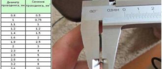
- First you need to properly prepare the tool for work. This does not mean its adjustment, made in the previous paragraph, but the use of appropriate extensions, the size of which depends directly on the diameter of the part being measured. To do this, use a caliper to measure the internal diameter of the part.
- The approximate value measured with a caliper will help you select the necessary extension cord for the device. Now let's figure out how to choose the necessary extension cord. The head of the device indicates its total length, for example, 75-88 mm or 50-63 mm (depending on the model of the device). The first value indicates the length without the tip, and the second - with the tip. It is important not to confuse it with GOST, since the GOST number is also indicated on the head, for example, in the form of GOST 10-75.
- This is what the instrument length marking looks like, which is indicated on the instrument head.
- When the total length of the tool is known, as well as the approximate size of the hole that is to be measured with a bore gauge to obtain accurate values, it is not possible to select a suitable extension. Extensions are also marked, so if the length of the hole being measured is 104 mm, then screw a 40 mm extension to the tool (for a 50 mm device). If there is no suitable extension cord in the kit, then we assemble it from several components, for example, 25 mm and 15 mm.
- The most difficult part of the work is completed, and now all that remains is to take measurements. We place the device inside the hole and, by rotating the drum, bring the tips into contact with the inner walls of the part.
- The device should be located in the center of the part. The tips should not be pressed too tightly against the walls, but with slight (very light) force. After this, the locking screw should be secured.
- We remove the device from the part and check the quality of fixation of the removable tip. If its fastening is loose, you need to tighten it and take repeated measurements.
- After removing the device, we begin taking readings. If you used a micrometer, then there will be no difficulties in determining the readings of the bore gauge.
- If you are hearing about a micrometer for the first time, then readings are taken as follows: first, we count the total length of the device including the tip. If we use a tool with a length of 75 mm and a head of 25 mm, then we immediately get 100 mm. Next, we look at the scale and count the number of marks. What scale should you look at? Many people often get confused here, but everything is very simple. Pay attention to the location of the zero. If it is located on top, then we count the upper marks, the division of which is 1 mm.
- Based on the example in the photo, we see 4 marks, that is, 4 mm. The last line exactly matches the drum, and there are no more lines below it, so we don’t look at the bottom scale. Now we count hundredths of mm on a vernier scale. We look at the vernier mark, which coincides with the longitudinal scale. The vernier division value is 0.01 mm, so from the example we see that the value is 0.01 mm. We add up the obtained data and get: 100 + 4 + 0.01 = 104.01 mm. This is the exact hole diameter of the measured part.
This is interesting! To ensure that the measurements taken are correct, it is recommended to repeat the process, but this time measuring the distance (diameter) of the inner surface of the workpiece in a different plane.
To be fair, it should be noted that the lower scale on the bore gauge has a division of 0.5 mm. As can be seen from the description, using a micrometric bore gauge is not at all difficult, and anyone can cope with this task if they first read the instructions. The video below shows how to use a micrometer bore gauge, the features of setting it up and reading readings.
Don't forget to take into account the instrument's error. Its value must be indicated in the passport data for each model.
General concept of compression
Among car enthusiasts, compression is often confused with the compression ratio specified in the car's operating instructions. These are different concepts, although there is some connection between them.
Compression is a variable value that reflects the actual pressure in each cylinder, measured when the crankshaft is rotated by the starter. It is never indicated in the vehicle’s technical passport, since it depends on a number of factors:
- tightness of cylinder-piston (CPG) and valve group seals;
- engine temperature;
- starter rotation speed and battery charge;
- the presence of motor oil in the work area where fuel combustion occurs.
Based on the actual pressure in the cylinders, it is customary to judge the degree of wear of the CPG and the condition of the valves. The lower the compression values, the worse the conditions for burning gasoline in the chambers. The air-fuel mixture does not burn completely and releases less energy, and engine power decreases.
The compression ratio is a constant characteristic equal to the ratio of the working volume (the internal size of the cylinder along with the combustion chamber) to the piston stroke length. It shows how many times the combustible mixture is compressed before the outbreak.
If the compression ratio is a dimensionless quantity, then compression is measured in units of pressure. The most common in the post-Soviet space is 1 physical atmosphere (Atm), but others are also found in modern pressure gauges:
- 1 Bar (equal to 0.99 Atm);
- 1 MPa (9.9 Atm);
- 1 kgf/cm2 (0.97 Atm) - used in Soviet times;
- 1 psi (0.068 atm).
Since compression measurement is always carried out with a certain error, differences in hundredths between the first three units are usually ignored.
How to use an indicator bore gauge: instructions for use
The procedure here is the same as in the previous case: first you need to configure the device, and only after that you can proceed to its direct use. We'll tell you how to solve each of these problems.
Verification
To determine the degree of accuracy of measurements and zeroing, a calibration ring or (if it does not exist) a gauge block, but only with a clamp, is suitable.
To reset you need to do the following:
- select a suitable replacement rod and install it on the metal rod of the selected model;
- set the device to the appropriate size and ensure sufficient pressure on the locking screw;
- fix the stem bushing (and with it the entire tool) in a vice;
- Rotate the head until the arrow points exactly to the zero mark.
Calibration of the bore gauge is carried out under the already described conditions, which are also relevant during operation: air humidity up to 80% and ambient temperature up to 25 degrees Celsius. The device should still be reset before each use. The interval between verifications is, again, 1 year, although they can be carried out more often if there is any suspicion that the current error exceeds the tolerances. The main thing is to adhere to the requirements of MI 2192-92.
Crankshaft
If the crankshaft is faulty, it can be repaired. The main function here lies on the necks. If they are damaged, it is better to replace them with new ones. Especially when tuning the engine. But if you do not want to replace, you can polish the crankshaft journals. What does this give? Mechanical stress wears out parts. And even minor roughness is unacceptable. Polishing increases the performance and wear resistance of the crankshaft journals. However, when repairing an engine, polishing the journals is often eliminated in practice to reduce the cost of repairs. But it’s still better to polish the necks as a whole. Or separately from engine repair.
How to use an indicator bore gauge and important points when working with the tool
An indicator bore gauge differs from a micrometric gauge not only in design, but also in purpose. The device is not used to obtain accurate distance or diameter values, but to determine deviations from the standard readings. As in the case of a micrometer instrument, the indicator instrument should be prepared for use before use. To do this, you will need a calibration ring (template), which is necessarily supplied with the tool. A special clamp or micrometer is used to adjust the bore gauge in preparation for measuring large holes.
- Work must be carried out in a temperature range from +15 to +25 degrees.
- The principle of setting is that you should initially select a replacement rod, which are supplied in the kit or purchased separately.
- The rod is fixed in the working part of the tool.
- If a micrometer or clamp is used, then it is necessary to set the size that corresponds to the rod used in the device.
- The bore gauge must be fixed in a vice through the stem bushing. However, you can instead clamp a micrometer with a preset value in a vice.
- The rod of the device is placed between the measuring jaws of a micrometer or a template clamp.
- Next, by rotating the indicator head, you need to align the arrow with the zero mark. To allow the indicator head to rotate, the locking screw must be loosened.
At this point, the setup process is considered complete, and you can proceed to the measurement procedure. How to use an indicator bore gauge correctly.
- The tool prepared for work must be placed inside the hole with the working part. Moreover, the rod of the device must be positioned strictly perpendicular.
- Correction of the position of the instrument is carried out by lightly rocking to the sides.
- Now the most important thing is that the exact value is determined by the arrow. Moreover, it should indicate a zero value, and at the slightest displacement of the rod to the sides, it should deviate to the right or left. If the arrow points to a specific value, then the level of deviation from the norm is calculated.
The device is quite easy to use, so people who have mastered the operating technology do not have any difficulties using it. Below is a video that shows how to set up the device for operation by setting it to zero, and also take measurements of the part.
The indicator bore gauge is used to measure the wear level of the cylinder block, connecting rods and other parts. With its help, you can determine the possibility of further operation of the CPG, which depends on the level of wear of the cylinder walls. It is with the help of an indicator device that you can determine the level of wear and draw subsequent conclusions.
Instrument care
In order for the bore gauge to serve for a long time, it is important not to buy the most expensive foreign model, but to provide proper care for the instrument. All measuring instruments require special attention to storage and operating conditions
The bore gauge is no exception, so in order for the tool to serve for a long time, it is necessary:
- Store it in heated rooms and avoid significant temperature changes.
- When working, do not drop the tool (especially pointer models), and also eliminate the possibility of its contact with aggressive media or water.
- If the device is supplied in packaging, then this is where it must be stored.
The device may fail if used incorrectly, so it is recommended that you first study the instructions for using the tool. Having considered the design, varieties, types, as well as the features of setting up and using bore gauges, it will not be difficult to use the tools when the need arises.
Publications on the topic
Learn how to use bubble building levels correctly
Indicator screwdriver and its use
Types of thread gauges and features of determining the thread pitch on bolts and nuts
Learning to take measurements with different types of micrometers
Working with micrometric bore gauges
In general, it is divided into two types: the first is preparation (adjustment, in order to confirm the accuracy of recording values, and zeroing), the second is direct reading. Let's look at both stages and actions at each of them.
Verification
We will present the general mechanism for its implementation below, in the section on operation. Here we will say that it is carried out only in relation to the model set “to zero”. To do this, at an ambient temperature of 20 0C, perform the following steps:
- place the spherical head of the tool between the jaws of the measure;
- press the required surfaces by rotating the drum;
- fix the assembly using a special screw;
- make sure that the longitudinal line on the stem is located exactly along.
Then they move on to taking readings.
We offer you to see how to set up a micrometric bore gauge; the video will answer those questions that arose during the reading process, and which would be too long to talk about in text format.
All actions should be performed in accordance with GOST 17215-71; According to this method, the interval between verifications is 1 year. The conditions for their implementation must always be the following:
- humidity level – no more than 80%;
- room temperature – from +15 to +25 degrees Celsius.
Attention, the device must be set to zero before each new reading. In order not to provoke distortion of the values, it is worth holding the instrument while adjusting by the bushing, which will not heat up from the heat of the hand, unlike the steel rod.