Information about the manufacturer of the key-milling machine 692D
Manufacturer of the special key-milling machine 692D Dmitrov Milling Machine Plant , founded in 1940.
The main products of the plant at present are universal cantilever milling machines of the “6K” and “6DM” range.
Machines produced by the Dmitrov Milling Machine Plant, DZFS
- 6D12
vertical cantilever milling machine 320 x 1250 - 6D81Sh
universal cantilever milling machine 250 x 1000 - 6D82Sh
universal cantilever milling machine 320 x 1250 - 6K11
vertical cantilever milling machine 250 x 1000 - 6K12
vertical cantilever milling machine 320 x 1250 - 6K81Sh
universal cantilever milling machine 250 x 1000 - 6K82Sh
universal cantilever milling machine 320 x 1250 - 6N11
vertical cantilever milling machine 250 x 1000 - 6N81
universal cantilever milling machine 250 x 1000 - 6N81A
universal cantilever milling machine 250 x 1000 - 6N81G
horizontal cantilever milling machine 250 x 1000 - 6Р11
vertical cantilever milling machine 250 x 1000 - 6Р81
universal cantilever milling machine 250 x 1000 - 6R81G
horizontal cantilever milling machine 250 x 1000 - 6Р81Ш
universal cantilever milling machine 250 x 1000 - 692D
vertical key-milling machine - 692Р
vertical key-milling machine - 692M
vertical key-milling machine
Scope of application of a hand router
Milling devices are mainly used for wood processing and carpentry, however, modern routers are capable of working with non-ferrous metals, plastics, stone and glass. Initially, stationary models were used for milling, which took up a lot of space and were used mainly in mass production. Handheld routers are compact and versatile. Hand routers are suitable for DIY work at home; they are equipped with different cutters and attachments for creating holes. Hand milling machine is used:
- to create holes on the surface being processed;
- to create recesses of the required shape;
- for cutting out door hinges;
- for creating decorative patterns;
- for adjusting the parts to be connected to size.
There are different types of manual milling machines. Each type is used in a specific area of work. Let's take a closer look at the types and scope of their application.
- Vertical or plunge router
. Used for cutting holes, grooves, recesses, etc. An easy-to-use tool that does not require special skills to operate. - Edging router
. Chamfering a surface, creating recesses and selecting a groove. The difference from other types is the ability to process laminate surfaces. Most often used in production. - A rotary router
is capable of finishing edges and cutting holes in metal, glass and drywall. - The blade router
is used exclusively for selecting and fitting grooves. - A filler router
is used among carpentry professionals to cut double holes to fit dowels.
Of the types of routers discussed above, the vertical router is considered universal; it is easy to use and capable of performing many jobs.
692D Vertical key-milling machine. Purpose, scope
692D -type key-milling machine 692р , which was put into production around 1974.
Specialized milling machines 692D are used in mass production to process parts that are similar in configuration, but different in size.
692D key-milling machine is designed for processing key grooves on shafts with measured and unmeasured end and key cutters and cutters manufactured according to TU2-035-858-82.
692D machine can process keyways with a width from 4 to 28 mm in a semi-automatic cycle.
Processing of grooves from 4 to 6 mm is carried out using a pendulum cycle with a measuring tool, and from 6 to 28 mm - to the full depth in one pass, followed by calibration of the width with a non-measuring tool.
The use of a device for calibrating the groove being processed on the machine ensures that the accuracy of the width of the keyway is maintained, regardless of the accuracy of the diameter of the cutters used (starting from a diameter of 6 mm).
On the 692D , the range of spindle speeds allows machining of keyways with both high-speed and carbide cutters over the entire range of slot widths with high productivity.
Machine design features
Longitudinal feed is carried out by moving the milling head along the guides of the bed head.
Vertical feed - spindle quill.
The groove is calibrated by moving the table transversely.
The drive of all listed movements is hydraulic. In addition, the machine has manual adjustment movements:
- longitudinal table;
- vertical table;
- vertical spindle quill;
- transverse head of the bed.
The spindle is driven by a 2.2 kW asynchronous electric motor through a gearbox and two-stage V-belt pulleys. The spindle speed is regulated by switching the gearbox handles and moving the V-belt on stepped pulleys from one stream to another.
Pendulum cycle of key-milling machine 692D
Keyways with a width of 4-6 mm are processed on a machine with a pendulum feed for plunging (pendulum cycle).
Keyways with a width of 6-25 mm are processed with drilling feed to the full depth and in one pass for the length of the groove (single-pass cycle).
To process precise keyways, the machine has a groove processing cycle with calibration of its width along two walls.
To process less precise grooves, there is a groove processing cycle with calibration of its width along one wall.
692D machine also has a groove processing cycle without calibration, when the width of the groove is provided by a cutter.
When cutting grooves to full depth, the drilling feed can be intermittent, which prevents the formation of long draining chips and its wrapping around the cutter.
In a pendulum cycle, the cutter is rapidly brought to the workpiece and moves along the workpiece at working feed. With each reversal of the longitudinal movement, the tool receives a periodic vertical infeed, the value of which is set on the dial and can range from 0 to 0.5 mm/stroke. After several longitudinal passes, the number of which will depend on the amount of vertical periodic feed, the groove will be cut to its full depth. It is possible to process a groove without calibration, with calibration of the groove width along one wall, with calibration of the groove width along two walls. The type of processing is selected using a switch on the machine console during setup.
The cycle without calibration ends after cutting the groove to a given depth, when the tool is quickly removed from the groove and moved to the beginning of the groove.
A cycle with calibration of the groove width along one wall is that after cutting a groove to a given depth, the workpiece is shifted perpendicular to its axis by the calibration amount, then the longitudinal calibrating feed is turned on and the tool processes one wall along its entire length, after which it is quickly removed from the groove .
The cycle with calibrating a groove along two walls differs from the previous one in that after cutting a groove to a given depth, the workpiece is shifted by half the calibrating movement, the tool processes one wall for its entire length, then the workpiece is shifted to the other side by the full amount of the calibrating movement and the tool processes the other wall of the keyway, after which the cutter accelerates upward, the milling head accelerates to its original position, the workpiece moves to the middle position, the cycle is completed.
A single-pass cycle differs from a pendulum cycle in that the tool, after an accelerated approach to the shaft with a continuous feed, mills the shaft to the full depth of the groove, and then, with a working feed, cuts the groove to a given length.
Once the groove has been cut to the specified length, there are three machining options, similar to those available in the pendulum cycle: without calibration; with groove width calibration along one wall; with calibration of the groove width along the two walls of the keyway.
The continuation of cycles after cutting a groove is the same as in the pendulum cycle.
The rotation speed and drive power of the main movement, the feed range and sufficient rigidity of the machine make it possible to process keyways with non-dimensional keyway cutters equipped with a hard alloy similar to cutters in accordance with GOST 6396-78, which significantly increases productivity compared to the processing of grooves with high-speed cutters.
Climatic modification and placement category of the machine UHL4 according to GOST 15150-69.
Modifications of the key-milling machine 692
692d - 1990.
Keyway width from 4 to 25 mm in a semi-automatic cycle, shaft diameter 12..75 mm 692r-1 - 1976. Key-milling machine
6d92r-1 - key-milling machine with a horizontal spindle
692r - 1975. Keyway width from 4 to 25 mm, depth up to 26 mm, length 5...300 mm. Shaft diameter 12..75 mm
6d92 - 1973. Keyway width from 6 to 32 mm. Horizontal spindle. Shaft diameter up to 120 mm.
692m - 1965. Keyway width from 4 to 24 mm, depth up to 40 mm, length 5...300 mm
692a - 1954. Keyway width from 3 to 20 mm, depth up to 26 mm, length 5...300 mm
How does a milling machine work?
September 24, 2019
Milling machine
Designed for processing smooth and uneven surfaces: edges, grooves, grooves.
The router is indispensable when creating highly artistic products from any type of wood, plywood, plastic, plexiglass, soft metals, etc.
To understand how a milling machine works, let’s look at its design using our Orson 1325 model as an example.
Design of the Orson 1325 CNC milling machine:
1. Bed – the base on which the table and portal are installed. The more stiffeners the bed has and the thicker the steel, the longer and more accurately the machine will work.
2. Table – the surface where the workpiece is attached for processing. The table can be:
- aluminum with bakelite coating and T-slot fastening;
- vacuum with a cellular surface with fastening with suction cups and a vacuum pump;
- hybrid vacuum table with T-slot mount.
An aluminum table is used for processing metal and stone; in all other cases, buyers prefer a hybrid table, because... it secures the workpiece better.
3. Portal – a structure installed on a desktop. It moves along guides using motors (stepper or servo).
4. Spindle - the shaft where the cutter is installed in the collet. The spindle comes with water and air cooling and is mounted on the machine portal.
5. Control unit - a special cabinet where drivers, inverter, controllers, and power distribution systems are installed.
6. Control program – installed on a personal computer and connected to the control unit of the router. The NC Studio program is used to control a 3-axis machine; Syntec is used for 4- and 5-axis machines with asynchronous spindle operation and automatic tool change.
The operating principle of a milling machine. 7 facts.
- The material is processed using a cutter, which is installed in a collet. The cutter is capable of grinding, drilling, engraving, and cutting the workpiece. The machine is usually supplied with a set of 5 cutters for roughing and finishing.
- The collet with the cutter is installed in the spindle, which is mounted on the portal.
- The portal moves the spindle with the cutter along three axes above the workpiece located on the work table.
- The movement of the spindle and portal along the axes is provided by motors (usually stepper, 3 pcs.).
- In order for the mechanical part to execute the necessary commands, a control program (NC Studio) is used that supports 3 axes, 3 limit sensors and spindle control. Consists of an interface board, a decoupling board and software that is installed on a PC.
- Before production begins, the CNC operator creates a product design in a graphics editor (AutoCad, ArtCam, CorelDraw) and saves it in G-code.
- Next, the file is loaded into NC Studio, which visualizes it and issues the appropriate commands to the mechanical part.
Thus, the operating principle of a CNC milling machine is that:
- the operator creates a command in a program on a PC,
- the program transmits the impulse to the cutter
- the cutter processes the material according to a given command.
CNC automates machining processes, increases production speed and minimizes waste. The quality of the products and, ultimately, your profit depend on how the router works.
Need some advice?
Leave a request, an engineer will call you back within 5 minutes.
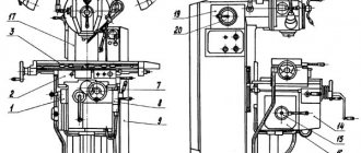
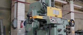
General view of the key-milling machine 692D
Photo of key-milling machine 692D
Photo of key-milling machine 692D
Photo of key-milling machine 692D
Photo of key-milling machine 692D
Photo of key-milling machine 692D
Metal milling machines
The process of processing metal workpieces, in which the cutting tool performs a rotational movement, and the workpiece mounted on the table is reciprocating, is called milling. Machines that can be used taking into account the given processing conditions are called milling machines. It is officially accepted that the first metal milling machine was invented in 1818. Eli Whitney was the first to receive a patent for an invention that became the basis for the creation of an entire group in the field of metalworking.
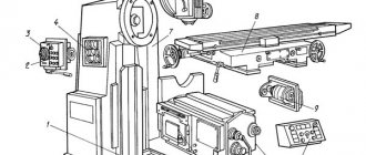
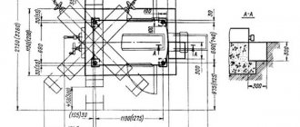
Arrangement of components of the key-milling machine 692D
Location of the main components of the 692D key-milling machine
Location of the main components of the 692D key-milling machine
Components of the key-milling machine 692D
- bed:
- gearbox;
- gearbox switching;
- milling head;
- casing;
- hydraulic equipment;
- hydroelectric station;
- hydraulic cylinder;
- console;
- emphasis;
- table;
- cooling;
- electrical equipment;
- electrical cabinet;
- accessories.
General structure of the milling machine
Each type of milling machine has its own specific design nuances, but their general structure is similar. You can highlight the most important components and mechanisms that provide the most important functions.
Milling machine diagram
Most milling machines have a unified design. They use a universal kinematic scheme. Rotational motion is provided by an asynchronous electric motor of sufficient power. Torque is transmitted to the shaft by a chain transmission through a semi-rigid coupling. Next, a gearbox is provided, including up to 8 gears. It allows you to rotate the working shaft according to several patterns. Vertical feed has a range from 8 to 267 mm/min, and transverse and longitudinal feed – from 25 to 800 mm/min.
The versatility of the design is created by the overrunning clutch on the reverse box. Torques are transmitted to a ball overload clutch set to the maximum permissible speed. The design of the machines includes the following main components.
Base
The unit is installed on a solid cast iron base, which ensures its stability during operation. It is equipped with a trough for collecting waste coolant. An electric pump is installed on the base to supply liquid to the working tool. This part has a simple shape to reduce the cost of production.
bed
The frame is securely fastened to the base using bolts. This is the most important part (essentially a housing) on which the main components are mounted. Some components are installed inside the frame (spindle, electric motor, gearbox), and some machine parts are located outside. At the top there are horizontal guides for moving the slider, and in front there are vertical guides for the console or spindle headstock. To increase the rigidity of the structure, the internal cavity is reinforced with ribs. Typically the frame is made of steel or cast iron. It can be cast or welded.
Crawler
A slider or trunk is used to fix and support the equipment. In horizontal and universal machines it is a mandatory element, but on vertical machines it may be absent. The unit is installed at the end of the horizontal guides of the frame. In vertical machines, the trunk can be a movable part of the milling head for moving the cutter in the vertical direction.
Console
The operation of the entire router largely depends on the quality of the console. This part is made of cast iron by casting. Installed on the vertical guides of the frame. The console's job is to move the horizontal guides for the slide. The strength of the unit is ensured by a stand with a telescopic screw that adjusts the height, as well as lateral supports.
Sled
The relationship between the X and Y axes is established by the slide. The upper guides are attached to them for moving the desktop in the longitudinal direction. Guides are mounted below to move the slide itself along the console. In horizontal machines, a slide is used to move the workpiece horizontally.
Clamps for the workpiece are installed on the table. It is mounted on a skid and moves on it. Together with the console and slide, the table is responsible for feeding the workpiece into the work area. It can move in longitudinal, transverse and vertical directions. Machine tools typically provide manual and mechanical feed control. Most machines have a function for accelerating table movement (high speed). Working feeds are regulated by a multi-stage switch (switch box). Their mode is selected by the worker, taking into account the type of material and type of cutter.
Technical characteristics of the machine 692D
| Parameter name | 692D | 692Р | 692M |
| Basic machine parameters | |||
| Accuracy class according to GOST 8-71 and GOST 8-82 | N | N | N |
| The largest diameter of the installed workpiece, mm | 12..75 | ||
| Processed groove width, mm | 4..25 | 4..25 | 4..24 |
| The greatest depth of the groove being machined in compliance with the requirements of GOST 23360-78 (GOST 7257-58, GOST 8788-68), mm | 9 | 10 | |
| Maximum total depth of the processed groove, mm | 26 | 26 | 40 |
| The largest diameter of the cutter installed on the machine, mm | 25 | ||
| Longitudinal movement of the milling head, mm | 5..400 | 5..300 | 5..300 |
| Maximum movement of the spindle sleeve by hand, mm | 100 | 100 | 100 |
| Maximum displacement of the spindle sleeve from the hydraulic drive, mm | 40 | 40 | 40 |
| Accelerated movement of the spindle sleeve from the hydraulic drive, mm | 14 | 14 | — |
| Dimensions of the working surface of the table (length x width), mm | 1000 x 250 | 1000 x 250 | 800 x 200 |
| Number of T-slots Dimensions of T-slots | 3 | 3 | 3 |
| Dimensions of the T-shaped middle slot, mm | 14N8 | 14A3 | |
| Dimensions of T-shaped outer slots, mm | 14N11 | 14A4 | |
| Installation longitudinal/vertical/lateral movement of the table manually, mm | 650/ 350 | 630/ 300/ 300 | 440/ 300/ 160 |
| Transverse movement of the table from the hydraulic drive (Value of the groove being processed during calibration), mm | 0,01..1,0 | 0,01..1,0 | — |
| Transverse installation movement of the spindle axis from the middle groove of the table in both directions, mm | ±5 | ±5 | |
| Internal spindle cone 7:24, according to GOST 24644-81 (GOST 15945-70) | 40 | 40 | KM3 |
| Number of spindle speed steps | 11 | 11 | 12 |
| Spindle speed, rpm | 400..4000 | 315..3150 | 375..3750 |
| Working feeds of the milling head - longitudinal, mm/min | 20..1400 | 250..1200 | 450..1200 |
| Working feeds of the milling head - vertical with a single-pass cycle, mm/min | 16..140 | ||
| Working feeds of the spindle sleeve for insertion - with a pendulum cycle, mm/min | 0,05..0,5 | 0,05..0,5 | 0,05..0,5 |
| Speed of rapid movement of the spindle sleeve (approach, retraction), mm/min | 200 | 200 | |
| Drive unit | |||
| Number of electric motors on the machine | 3 | 3 | 2 |
| Main motion drive electric motor, kW (rpm) | 2,2 (1500) | 2,2 | 1,1/ 1,6 (950/ 1440) |
| Hydraulic pump electric motor, kW (rpm) | 1,1 (1000) | 1,1 | — |
| Coolant pump electric motor, kW (rpm) | 0,12 (3000) | 0,12 | 0,125 (2800) |
| Total power of electric motors, kW | 3,42 | 3,42 | |
| Dimensions and weight of the machine | |||
| Machine dimensions (length width height), mm | 1615 x 1600 x 2210 | 2080 x 1640 x 1860 | 1520 x 1400 x 1750 |
| Machine weight, kg | 2250 | 1800 | 1250 |
- Avrutin S.V. Fundamentals of Milling, 1962
- Avrutin S.V. Milling, 1963
- Acherkan N.S. Metal-cutting machines, Volume 1, 1965
- Barbashov F.A. Milling business 1973, p.141
- Barbashov F.A. Milling work (Vocational education), 1986
- Blumberg V.A. Milling machine handbook, 1984
- Grigoriev S.P. Practice of coordinate boring and milling work, 1980
- Kopylov R.B. Working on milling machines, 1971
- Kosovsky V.L. Handbook of a young milling operator, 1992, p. 180
- Kuvshinsky V.V. Milling, 1977
- Nichkov A.G. Milling machines (Machinist's Library), 1977
- Pikus M.Yu. A mechanic's guide to repairing metal-cutting machines, 1987
- Plotitsyn V.G. Calculations of settings and adjustments of milling machines, 1969
- Plotitsyn V.G. Setting up milling machines, 1975
- Ryabov S.A. Modern milling machines and their equipment, 2006
- Skhirtladze A.G., Novikov V.Yu. Technological equipment for machine-building industries, 1980
- Tepinkichiev V.K. Metal cutting machines, 1973
- Chernov N.N. Metal cutting machines, 1988
- Frenkel S.Sh. Handbook of a young milling operator (3rd ed.) (Vocational education), 1978
Bibliography:
Related Links. Additional Information
- Milling machines: general information, classification, designation
- Comparative characteristics of cantilever milling machines of the 6N, 6M, 6R, 6T
- Feed box for console milling machines of the 6M : 6M12P, 6M13P, 6M82, 6M83, 6M82Sh, 6M83Sh
- Feed box for console-milling machines of the 6P : 6Р12, 6Р13, 6Р82, 6Р83, 6Р82Ш, 6Р83Ш Feed box for console-milling machines of the 6Т : 6T12, 6T13, 6T82, 6T83, 6Т82Ш, 6Т83Ш
Electrical equipment of milling machines of the Gorky Machine Tool Plant, GZFS
Electrical equipment of milling machines of the Vilnius Zalgiris Machine Tool Plant
We work with the milling machine correctly
Initially, you need to select the most suitable cutter. It must correspond to the task being performed and the material to be processed.
After which the nozzle is fixed on the machine in a special “chuck”. The fixation should be tight.
Tool settings are carried out: milling depth, speed and all others. CNC machines are programmed and this is a rather complex process.
We put the handle in the desired position and put the machine into operation.
The router can be held in your hands if it is manual, or you can fix it in a special rack, which is not difficult to make yourself. It is universal and is successfully used as the basis of the same drilling machine and many others in the home workshop.
The working part of it, for a stationary installation, should be on top. Do not forget to use a template for safe and better work.