Description, passport
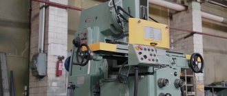
This is a unit in which the work table has increased dimensions, and the equipment itself is equipped with a more powerful main engine than its predecessors and analogues. It is distinguished by a significant margin of safety, reliability and functionality of components that have their own design features in this equipment.
The machine is automated and is configured for different automatic cycles. This significantly improves productivity indicators, especially since it is not necessary to look for a highly qualified worker for such equipment.
The passport of the milling machine can be downloaded for free from the link - Passport of the cantilever milling machine 6Р82Ш.
Installation drawing
The drawing is calculated individually depending on the room. The standard drawing is presented so that the equipment fits when rotated 45 degrees on any plane.
Limits of machine use in terms of power and power loads
The operating limits of the drive are determined only by the indicators of the electric motor installed in the equipment (if carried out at more than 63 revolutions per minute). If the number is less than 63, then the power of the main drive is reduced. The cutting force for longitudinal feed is a maximum of 1500 kgf, transverse - 1200 kgf, vertical - 500 kgf. The maximum workpiece size for roughing is up to 160 millimeters.
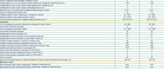
Specifications
Maximum table movement in cm:
- across the axis - 32;
- along – 80;
- vertically – 42.
Accelerated table movement cm/min:
- along – 400;
- across – 400;
- vertically – 133.
The maximum weight of the workpiece for processing is 1 ton. 18 stages of working table feeds. the distance from the end of the spindle to the table is from 3 cm to 45. The distance between the trunk and the spindle axis is 15.5 cm.
The spindle has 11 speeds, and the spindle rotates with a frequency from 31.5 rpm to 1600 rpm. The weight of the machine is 3.3 tons.
Kinematic diagram of the 6T82G milling machine
Kinematic diagram of the 6T82G milling machine
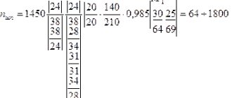
The feed drive is carried out from a separate flange electric motor mounted in the console. Working feeds are adjusted using switchable gears of the feed box, consisting of two three-crown blocks and one movable gear with a cam clutch. On the last shaft of the box in the kinematic chain of working feeds, an adjustable ball spring clutch is provided, which protects the feed mechanism from overload.
From the last shaft of the feed box, the movement is transmitted to the console. Then, through a series of cylindrical and bevel gears mounted in the console and slide, one of the three lead screws is rotated by engaging the corresponding jaw clutch, and thus longitudinal, transverse or vertical feeds are carried out.
Switchable gears of the feed box allow you to get 18 different feeds with different gears.
The kinematic chain for accelerated (installation) movements of the table, slide and console is performed by transmitting motion from the engine through parasitic gears directly to the gear of the high-speed clutch mounted on the last shaft of the feed box.
The specified clutch is interlocked with the working feed clutch, thereby eliminating cases of their simultaneous activation.
Advantages and disadvantages
Advantages of this machine:
- In addition to milling operations, the machine can be used for planing, grinding, and dimensional cutting.
- Technological equipment and readjustment of equipment do not seem difficult.
- The machine is compact for its capabilities and has low energy consumption.
- High precision parameters in the manufacture of final products.
- The unit is manufactured with increased versatility parameters, which allows the use of different types of cutters.
A disadvantage is the incomplete cooling of individual sections of the spindle.
Design features
The front head with a spindle is designed on a movable trunk and is capable of rotating at an angle in different planes located perpendicular to each other. You can work with two spindles separately and simultaneously.
To expand the capabilities of the equipment, in addition to the earrings, an additional overhead head was installed. It helps to process large-sized parts, as well as carry out simple boring work.
There is a backlash sampling mechanism that allows for up and one-and-a-half milling in standard mode and in mode with automatic cycles.
List and location of components
The 6Р82Ш machine consists of the following main parts:
- vertical base (bed) with guides;
- foundation slab;
- tool console with movable slides;
- rotating plate (trunk);
- Desktop;
- high-speed box, which is hidden inside the frame;
- gearbox mechanism;
- rotary or additional head;
- machine controls;
- containers containing cutting fluid.
As a result, the desktop can move in all three coordinates. To eliminate vibrations, the center of gravity is located below the surface of the working movable table.
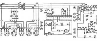
Electrical equipment of the 6R83G machine
Electrical diagram of milling machine 6R83G
Kinematic diagram of the milling machine 6р83г
Notes
- * – only for machines 6Р82Ш, 6Р83Ш
- ** – to the electrical diagram of the tool clamping mechanism
- *** – only for machines 6Р13Б
Supply network: Voltage 380 V, alternating current, frequency 50 Hz
Control circuits: Voltage 110 V, alternating current
Control circuits: Voltage 65 V, DC current
Local lighting: voltage 24 V.
Rated current (sum of rated currents of simultaneously operating electric motors) 20 A.
The rated current of the protective device (fuses, circuit breaker) at the power supply point is 63 A.
Electrical equipment is made according to the following documents: circuit diagram 6Р13.8.000Э3. connection diagram of the product R13.8.000E4.
List of controls
The unit in question has two control modes: manual and automatic. The basis of management includes:
- handles to switch the action of gearbox mechanisms and speeds;
- buttons that allow you to turn various components on and off;
- small flywheels to move the table in standard mode;
- handles for moving the movable panel;
- organs that control the rotation of the spindle itself;
- button responsible for emergency stop of the unit.
Different handles are located on both sides of the unit.
Main components and mechanisms
Standard components and mechanisms of a milling machine have their own design features.
When the main engine is turned on, the electromagnetic clutch starts. Through a gear system, the movement is transmitted to the tool head with spindles. Using a flywheel, the trunk, which contains a gearbox, is moved.
To set the required speed, you must switch individual stages using a special belt drive mechanism. All main components of the machine are united by a console. It controls variable coordinates.
Lubrication of the shift unit directly from the lubrication of the gear mechanism by spraying oil from a tube located in the upper part of the frame.
§ 2. WIDELY UNIVERSAL MILLING MACHINE MODEL 6Р82Ш
Section: LIBRARY OF TECHNICAL LITERATURE Short path https://bibt.ru <<Previous page Table of contents of the book Next page>> On a universal milling machine model 6Р82Ш they perform various complex work: manufacturing metal models, dies, molds, templates, cams etc. The machine has a horizontal spindle, which can be used for processing planes with end and cylindrical cutters. A rotating head is mounted on the trunk and an overhead head can be installed on it.
Supports can be installed on the machine trunk guides to support long mandrels when working with a horizontal spindle. In addition to the usual accessories necessary for the daily maintenance of the machine, the machine can be supplied with a dividing head, a round table, and a slotting head, which significantly expand the capabilities of the machine.
In Fig. 53 shows the main components of the machine model 6Р82Ш, and in Fig. 54 its controls are indicated.
Duplicate controls are provided for ease of operation when the worker is located at the side of the machine near the gearbox.
Rice. 53. Main components of the machine model 6Р82Ш:
1 - base, 2 - bed, 3 - electrical equipment, 4 - gearbox, 5 - gearbox, 6 - trunk, 7 - swivel head, 8 - overhead head, 9 - table and slide, 10 - console, 11 - feed box
Rice. 54 Controls of the machine model 6Р82Ш:
1 — “Stop” button (duplicate), 2 — “Spindle squeak” button (duplicate), 3 — arrow-speed indicator, 4 — spindle speed indicator, 5 — “Quick stop” button (duplicate), 6 — button “Impulse, spindle”, 7 - lighting switch, 8 - handwheel for manual movement of the trunk, 9 - speed switching handles for the spindle of the rotating head, 10 - clamping mechanism (earrings, supports), 11 - clamping mechanism for the rotating head, 12 - handwheel for extending the spindle sleeve , 13 — handle for clamping the sleeve and spindle, 14 — sprocket of the automatic cycle mechanism, 15 — handle for turning on the longitudinal movements of the table, 16 — table clamping mechanism, 17 — handwheel for manual longitudinal movement of the table, 18 — “Quick stop” button, 19 — “ button Spindle start", 20 - "Stop" button, 21 - switch for manual or automatic control of the table, 22 - handwheel for manual transverse movements of the table, 23 - dial for the mechanism of transverse movements of the table, 24 - vernier ring, 25 - handle for manual vertical movements of the table, 26 — button for fixing the feed switch fungus, 27 — feed switch fungus, 28 — table feed indicator, 29 — table feed indicator arrow, 30 — handle for turning on the transverse and vertical table feeds, 31 — handle for clamping the slide on the console guides, 32 — handle turning on the longitudinal movements of the table (duplicate), 33 — handle for turning on the transverse and vertical feed of the table (duplicate), 34 — input switch “On-off”, 35 — cooling pump switch “On-off”, 36 — horizontal spindle rotation switch “Left” - to the right", 37 - handwheel for manual longitudinal movement of the table (duplicate), 38 - handle for switching the rotation speed of the horizontal spindle, 39 - reversible switch for the direction of rotation of the spindle of the overhead head, 40 - control switch "Automatic cycle - manual movement - work with a round table" , 41— handle for clamping the console on the frame, 42 — screw for clamping the trunk on the frame, 43 — cover
Skip to navigation
Compliance with safety regulations
Safety precautions when working on a milling machine include rules of conduct not only during operation, but also when preparing the equipment:
- button up your sleeves and put on a hat;
- check the presence of a protective shield and proper grounding;
- check the serviceability of the machine at idle speed;
- Do not use a faulty tool or a dull cutter;
- It is prohibited to leave the working machine or be distracted from work;
- It is prohibited to take measurements while the cutter is rotating;
- You also cannot remove shavings with your hands or rags;
- upon completion of work, it is necessary to turn off the machine from the general power network;
- Lubricate all machine guides.
If you do not follow safety rules, working on a milling machine can lead to injury.
Analogs
The main analogues of the 6Р82Ш machine include the following units:
- 6Р83Ш – widely-universal cantilever milling machine 400x1600;
- 6Р83 – cantilever milling machine 400x1600;
- 6R82G – horizontal cantilever milling machine 320x1250.
The entire 6P series was put into production by the Gorky plant in 1972, and machines of this series are still produced and are popular because they are reliable.
The 6Р82 Ш cantilever milling machine is successfully used for the widest range of milling work. Workpieces weighing up to 1 ton can be milled on both sides of the machine, which is another advantage and useful design feature. It is also possible to carry out simple boring operations using this equipment.
In terms of size and performance, the unit is successfully used not only in small-scale and individual production, but also in some large repair enterprises, especially since the machine itself is very reliable and has been working without interruptions for more than one year. If the main components are severely worn, they are replaced and the machine is back in service for a long time.
Operational Capabilities
The technical characteristics specified for the 6T82G machine allow it to be used in many production and technological lines for milling products of varying complexity. Standard options are expanded by the use of additional devices and equipment:
- vice;
- dividing head;
- overhead milling head;
- slotting head;
- round rotary table with mechanical gear drive.
The components are installed on 6T82G horizontal milling machines by fixing them in standard grooves. The technical characteristics of the equipment are wider than those of conventional analogues. The console machine has a table with a wide range of movement in three directions, which expands technological capabilities. Simple equipment with a horizontal spindle does not have this option. The 6T82G circuit with an electromagnetic clutch provides overload protection. This is an effective mechanism that protects against breakdowns, since the engine power and the traction forces of the table drives can seriously damage the structure of the machine and cause injury to the worker.
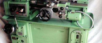
General view of the 6T82G milling machine
This equipment performs the entire list of milling operations for this class of machines. When working with equipment, all known metal processing techniques are used. Depending on the location of the cutting edge on the tool, the workpieces are processed:
- vertically;
- horizontally;
- by copier;
- with the help of additional devices.
When working, it is assumed that you have access to the equipment, issued accordingly, so there is no description of the basic concepts of metalworking in the passport. But there are recommendations for choosing processing modes. The machine has wide capabilities when working with parts of different strengths and surface areas. The spindle rotation speed varies over a wide range, and the table feed is finely adjusted. Using these values, optimal modes are selected to achieve specific goals, achieving:
- high performance;
- specified surface roughness;
- maintaining the temperature in the required range;
- safety of the cutting tool.
Convenient control allows you to quickly reconfigure the machine, install and dismantle additional equipment. The design elements are unified. Installation of cutters and equipment is carried out with standard tools according to the usual scheme. When processing metals, it is permissible to use the recommended tool. The cutters can be made from either high-speed steel or carbide-tipped products. Each type of cutting tool has its own recommendations, for which it will not be difficult to adjust the machine.
With high reliability, durability, and accuracy, the machine has a relatively affordable price and, accordingly, a quick payback. The list of operations performed allows the equipment to be used in many areas of activity. When operating conditions are met, the device is safe for the milling operator. Long service life and maintainability have become the decisive factor when choosing equipment for installation in small private organizations and large metalworking enterprises. If for the former it is a machine that is excellent for producing single products, then for the latter it is a tool for increasing labor productivity.
The letter “T” in the abbreviation of the name means a generation of equipment, and in contrast to previous releases of the “P” series, the power has increased significantly, the frequency range of spindle rotation has been expanded, and the table feed speed has been increased, including in accelerated mode. The controls have become more convenient, and the design of the machine has become more ergonomic.
