Articles
All photos from the article
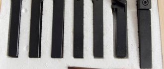
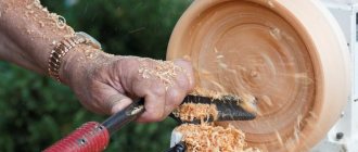
In order to produce various decorative elements from wooden blanks on lathes, special devices are required - wood turning tools. You can purchase them ready-made, but a set of such tools is often very expensive, so we will consider the option of making them ourselves.
The work is quite simple, the main thing is to have the necessary tools and equipment at hand.
In the photo: this is what a standard set looks like, with which you can do almost any job
In what cases is it necessary?
During operation, chips rub against the working surface of the tool. Due to the increase in temperature during operation, the part wears out. If sharpening is not carried out, the full service life of the part and all equipment is significantly reduced.
The documentation indicates acceptable cutter wear parameters. If these parameters are exceeded, the tool cannot be used. It must be sharpened along the front and back surfaces.
The permissible amount of wear differs depending on operating conditions and ranges from 0.3-2 mm.
Tool Technologist's Pocket Guide
For sharpening and finishing cutting tools, universal and special sharpening machines are used. In addition, cylindrical, flat and profile grinding machines are used to process cutting tools. Sharpeners are designed primarily for sharpening all types of cutters. In the absence of special sharpening machines, drills are sharpened using sharpeners. Sharpening the front surfaces of cutters on sharpeners is done with the end of the circle, and the rear surfaces with the periphery of the circle. Universal machines are used for sharpening and finishing of all types of cutting tools and have a set of devices that facilitate the installation and securing of the sharpened tool.
Special sharpening machines are designed, as a rule, for sharpening and finishing cutting tools of one type - cutters, drills, broaches, hobs, etc.
Recommended types of machines for diamond abrasive processing of cutting tools are given in table. 115.
Universal sharpening machines. The main types of universal sharpening machines are models ZA6ChM, ZB641, ZV641, ZB642, ZV642 and 3B 643. A distinctive feature of these machines is that the tool being sharpened, mounted on the machine table, can be moved relative to the grinding wheel in two mutually perpendicular directions. The vertical movement of the tool being sharpened relative to the grinding wheel is carried out either by moving the table, or it is communicated to the grinding headstock.
Installation and fastening of cutting tools on universal sharpening machines is carried out by devices that are accessories to the machines.
For machines of models ZV642, ZB642 and others, in addition to a set of accessories, they can, at the customer’s request, supply devices for sharpening drills, countersinks, taps, face and hob cutters, gear-cutting heads, broaches, small-sized and shaped tools.
According to ENIMS data, in table. 116 provides brief technical characteristics of the new universal sharpening machines.
Table 115
Recommended machines for diamond abrasive processing of cutting tools
Table 116
Technical characteristics of universal sharpening machines
Continuation of the table. 116
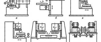
Equipment for sharpening cutters. It is recommended to sharpen and fine-tune cutters with a height of up to 50 mm on special machines models ZB6ZZV (with abrasive wheels) and ZB632V (with diamond wheels).
Sharpening on these machines (Fig. 82) is performed with ABC-shaped wheels with a diameter of 200 mm (ZB632V) and 250 mm (ZBbZZV). Grinding wheels are installed at the ends of the spindle, which is the shaft of a built-in two-speed electric motor. The grinding head is installed on the frame. On both sides of the grinding head there are oscillating tables with circular guides, providing an inclination angle from -10 to +20°. The guides are connected to the base through leaf springs, on which the table easily oscillates along the end of the circle. The upper part of the table is rotated by the rear angle α or α1. Plane angles φ or φ1 are set using protractor scales. When sharpening with a rigid attachment of the cutter, a protractor with a clamp is used, and when sharpening manually, a rotary protractor is used.
Rice. 82. Machine model ZB632V for sharpening cutters
The machines are supplied with devices for sharpening the front surfaces and for forming holes. The holes are formed by an A5P-shaped circle with a diameter of 80 mm and a profile radius of 2.5 mm.
Characteristics of the machine model ZB632V
For electric diamond sharpening of cutters, the Mukachevo Machine Tool Plant produces machine tools model 3623.
Adaptations. For sharpening and finishing of cutting tools, we recommend the devices included in the set of universal sharpening machines model ZA64M: two-turn and three-turn vice and a tool rest for sharpening and finishing of cutters; universal four-rotary heads using a rest or dividing mechanism for sharpening and finishing multi-edged tools.
Rice. 83. Double-turn vise
Double-rotary vice is designed for sharpening prismatic and disk cutters. They can be rotated in horizontal and vertical planes. The rotation angles are counted using the G and N scales. In Fig. 83, and a diagram of the installation of prismatic shaped cutters is shown. Installation is reduced to tilting the vice on the H scale at an angle α + γ and turning the vice in the horizontal plane at an angle K.
In Fig. 83, b shows a diagram of the installation of disk shaped cutters. When installing disk cutters, the center of the cutter is shifted relative to the end surface of the circle by the radius r to the circle of the control mark, then the vice is rotated in the horizontal plane by an angle λ, thereby ensuring sharpening of the cutter at the specified angles γ. α and λ. To ensure linear rather than planar contact of the cutter with the wheel when sharpening with the end of the grinding wheel, it is necessary to rotate the grinding head to an angle of 1-1.5°.
Three-rotary vice (Fig. 84) is designed for sharpening and finishing of cutters and flat broaches in one installation.
The vice has rotation in three mutually perpendicular planes. According to the G scales,
B and H, rotation angles are counted from 0 to 360°, scale divisions are 1°.
Since the surface to be sharpened must be parallel to the working surface of the wheel and the feed direction, it is necessary to rotate the cutter around an axis parallel to the surface to be sharpened. Since the vice does not have such a rotation, to align the sharpened and working surfaces of the circle, it is necessary to rotate the cutter around the axis of the device at angles ƟB, ƟG, ƟH.
Calculation of the angles of rotation of the vice at a given sharpening angle of the cutter is carried out according to the formulas given in table. 117. The initial position of the cutter for calculation is shown in Fig. 84.
Rice. 84. Three-turn vice
Table 117
Formulas for calculating vice adjustment angles
Continuation of the table. 117
Device for sharpening hob cutters. Sharpening is carried out along the front surface of the tooth with a disc-shaped grinding wheel. The largest diameter of the cutter that can be sharpened on the device is 220 mm, and the helix angle is from 0 to 25°.
The device (Fig. 85) consists of front and rear headstocks and a carbon ruler. A spindle 2 is mounted in the body 1 of the headstock. At one end of it, a gear 3 and a sleeve 4 with a stop 5 are freely mounted. A washer with a replaceable dividing disk b attached to it is placed on the sleeve 4. A bracket 7 with a handle 8 is attached to the gear sleeve 3, the tooth of which fits into the groove of the dividing disk.
Rice. 85. Device for sharpening hobs
Gear 3 engages with rack 9. At one end of the rack, a slider 10 is installed on a pin, which fits into the groove of strap 11. The strap is fixed to disk 12, the pin of which fits into the recess of bracket 7. Disk 12 together with strap 11 can be rotated relative to bracket 13, Moreover, the angle of rotation is measured on the L scale. After rotation, the position of the disk 12 with the bar 11 is fixed with a nut 14. Rotation of the disk 12 is necessary to obtain the required angle of inclination of the groove for the cutter being sharpened, indicated on the end of the cutter.
Angle α is determined depending on the longitudinal pitch S (mm) of the helical groove of the cutter according to the formula
The values of the angle α depending on the longitudinal pitch S are given in table. 118.
Table 118
Values of the angle α of rotation of the ruler depending on the longitudinal pitch S of the helical groove of the cutter
The device for sharpening cutters (Fig. 86) allows you to sharpen face and disk cutters with a diameter of up to 350 mm on universal sharpening machines. Sharpening is carried out along the end and diameter. The device consists of a plate 1, a base 3, a head body 6, a spindle 5, a rod 7, a disk 8 and an adapter sleeve 4.
The cutter to be sharpened is installed on a mandrel in spindle 5 and tightened from the reverse side with a bolt. When sharpening the main rear surface to an angle a, the head body 6 is turned on a scale of 9 by the value of the angle in the plan, and on a scale 2 (distorted rear angle a) by the value of the angle αset. The value of the installation rear angle αset is determined by the formula
When sharpening the auxiliary rear surface at an angle α, the body 6 is turned on a scale of 9 by the angle in terms of the transition cutting edge, and on a scale of 2 by the value aust obtained from the above formula (Table 119).
Table 119
Values of the installation clearance angle αset
The center device (Fig. 87, a) consists of front 1 and rear 2 headstocks, installed on the upper platform of the machine support rotary table. The headstock has a fixed center and a leader, and the tailstock has a movable center. This device is intended for sharpening and finishing of end tools that have center holes, and attachment tools mounted on center mandrels.
Rice. 86. Device for sharpening cutters: a - general view; b - design
The universal head is used for sharpening tools with tapered shanks or tools mounted on cantilever mandrels (Fig. 87, b). The head consists of a base 1, a bracket 2, a spindle 3 and a body 4. The spindle has a conical hole for securing mandrels and tool shanks. The inside of the spindle has two tapers - on one side there is a Morse taper No. 5, and on the other there is a No. 7/24 taper. A dividing disk is mounted and secured on the spindle. The head body can be installed at an angle in the horizontal (ƟG) and vertical (ƟV) planes.
Rice. 87. Center device (a) and universal head for sharpening machine (b)
The rotation angle is measured using the G.V scales marked on the bracket and body. By turning the spindle, you can use the H scale to set the surface to be sharpened relative to the tool axis at an angle ƟН.
Using a centering device and a universal head, sharpening is carried out on the front and back surfaces of multi-edge tools. The surface of the tooth to be sharpened relative to the wheel is set using a stop mounted on the machine table (for sharpening a straight-toothed tool) and on the grinding head (for sharpening a tool with a screw tooth).
The displacement value (N) of the support is determined by the formulas given in table. 120. The amount of displacement of the stop is set according to the dial of the ring of the lifting screw of the grinding head with an accuracy of 0.02 mm. If the tool is sharpened with the end of a cup wheel, the stop is lowered by the value R; if the tool is sharpened with the periphery of a PP-shaped wheel, the stop is set at the height of the centers, and the grinding spindle is raised by the amount H.
Table 120
Formulas for determining the displacement value (N) of the prop
Continuation of the table. 120
see also
reference-tehnologa.ru
Tools and accessories
Depending on the alloy, hardness, sharpening angle and other technological details, it is necessary to select a tool for sharpening the cutters. Each device has its own advantages and disadvantages.
Musaty
An effective tool, which is a metal rod with a ridge. Processing is carried out using a handle.
Sharpening stones
Another option for manual processing. Sharpening cutters using sharpening stones requires skill, which can only be acquired with experience. The cutter must be applied to the part and passed over it at least 10 times.
Mechanical sharpeners
Automated sharpening method. First you need to set the input parameters and, depending on them, actively operate the tool.
Electric sharpeners or sharpening machine
This is the most universal and simple method. The sharpening machine is convenient to use; in appearance it resembles a metal bar with holes of different sizes.
Emery, diamond wheel
The diamond wheel is widely used because it ensures high cleanliness of cutting surfaces. Also, with the use of diamond wheels, the service life of sharpening cutters increases - the number of possible resharpenings increases by 20-30%.
Emery and diamond wheel for sharpening cutters
Sharpening turning tools is the processing of the working surface, which consists of giving the required shape and angle to a new or dull tool.
Diamond wheel for sharpening cutters
At the end of sharpening, a finishing procedure is carried out, during which the tool is sharpened and the working surface is finally cleaned.
Sharpening turning tools and its types
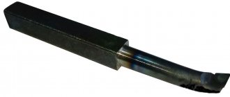
The geometric features of a cutting tool for wood or metal predetermined its most vulnerable cutting tool. But despite this, they are widely used in practice. The process of manufacturing parts on machines, first of all, involves cutting blanks to the required size.
Sharpening the cutting tool must be done carefully so as not to damage the cutting part of the tool.
Large metalworking plants always have sharpeners. In addition, large-scale production includes the presence of boring machines to give the cutters a working condition. In small workshops they do it themselves.
Detailed diagrams and instructions on how to do it yourself
The master must know the complete technological process in order to properly sharpen the tool with his own hands.
Technological process
The technological process includes several main points:
- The rear surface is machined at an angle equal to the rear angle of the holder.
- At the second stage, the cutting surface itself is processed.
- The sharpening angle should be a couple of degrees greater than the back cutting angle by a couple of degrees.
- Already at the third stage, the rear angle is formed.
After finishing, grinding follows as the final stage of sharpening.
Conducting fine-tuning
Finishing should be carried out according to the chosen method. Basic moments:
- cutters are not immersed in water, as they may break;
- When finishing, be sure to supply water for cooling;
- First, the back face is processed, then the main and auxiliary faces.
Grinding
Grinding is carried out using an emery wheel. The best option is a fine-grained model.
What is required for the work
Let's consider what materials and devices will be needed first of all in order to make homemade cutters for a wood lathe:
| Sharpening machine | A compact option for home use is also suitable, the main thing is that it has a high-quality abrasive wheel, and to sharpen some product options, it is advisable to have sharpening discs of different configurations. |
| Blanks for cutters | For these purposes, it is necessary to use hard steel grades, the most common option is P6M5. Home craftsmen often use old files, taps and other improvised elements (bearing races, etc.). |
| Wooden handles | In order to make it convenient to work with the tool, it is necessary to equip them with a handle, which can all be made on the same lathe, or you can purchase several pieces ready-made. They are available for sale at any hardware store, and their price is quite affordable. |
Important! When carrying out work, you should use protective equipment: gloves and goggles. You should also wear clothing that covers all exposed areas to prevent sparks from causing burns.
A rotating abrasive wheel poses an increased danger; carry out work carefully and slowly
Safety precautions
Every master who works on a lathe must be able to sharpen cutters with his own hands. It is only important to follow the safety rules. To do this, it is necessary to use protective equipment for the face. Touching the machine or the cutter is allowed only after it has completely cooled down.
Sharpening cutters for a machine tool is one of the most important technological processes that any qualified turner should be able to perform. The details of the process depend on the type of cutter, the work performed and the degree of wear.
how to sharpen cutters for a lathe correctly: types of wheels, sharpening angles
Sharpening the cutter consists of giving the shape and the required angle to the working surface. Sharpen new or dull tools. After sharpening, finishing is carried out, during which the tool is sharpened and the working surfaces are finally cleaned.
Types of sharpening
various types of metal cutters
Large metalworking factories specially maintain a staff of sharpeners and special machines for bringing the cutters into working condition. Employees of small workshops have to do this themselves.
Sharpening can be done in several ways:
- abrasive (on grinding wheels);
- chemical-mechanical (metal is treated with special compounds);
- using special devices.
Abrasive sharpening can be carried out on a sharpening machine, lathe or manually on a grinding block. It is very difficult to sharpen a tool manually at the required angles. The process is complicated by the fact that the metal heats up and loses its properties. Therefore, the result directly depends on the skills of the turner and his knowledge of sharpening angles.
Carbide tools are sharpened on green carborundum. Cutters made of various types of steel are processed with grinding wheels made of medium-hard corundum. Primary processing is carried out with whetstones with an abrasive of 36-46, final - 60-80. Before installing the wheel on the lathe, it is necessary to check the integrity. During operation, it can split and injure the worker, as well as ruin the sharpening angle.
The chemical-mechanical method is very effective and fast, provides a clean, smooth surface, and prevents the formation of chips and cracks. Used for sharpening large carbide cutters. They are treated with a solution of copper sulfate. The reagent forms a thin protective layer, which is washed off by the abrasive grains present in the solution. The process takes place in a machine equipped with a container with a movable grinder. The fixed cutter moves back and forth and with a pressure of about 0.15 kg per square meter. the centimeter is pressed against the abrasive surface.
On specialized machines, sharpening of cutters is carried out with white wheels made of electrocorundum (high-speed tools), green wheels made of silicon carbide (carbide), and diamond wheels (for finishing).
Sharpening process
sharpening the cutter on a grinding wheel
First, sharpen the main flank surface, then the auxiliary flank surface, the front surface and then the radius of curvature of the end. At the end of the work, the sharpening angles are checked against the template.
To ensure an even and smooth edge, the tool must be constantly moved along the grinding surface. With this type of work, the wheel lasts longer and wears out evenly.
The tool can be processed dry or with constant water cooling. The water flow must be sufficient and continuous. If the tool is sharpened dry, there is no need to periodically water it or dip it in a container of water. This causes cracking of the surface and destruction of the working edge.
Manual finishing is carried out:
- fine-grained whetstone using technical oil, kerosene or - tools made of various types of steel;
- circle made of copper using boron carbide paste and technical oil.
Only the cutting surfaces of the tool are adjusted with an edge width of up to 3 millimeters. It is more efficient to finish the cutters on a machine with a cast iron touchstone. The procedure is simple and does not require much time, but significantly extends the service life and productivity of the instrument. It is important to maintain the required angles!
Videos about sharpening different types of cutters:
Detailed diagrams and sharpening instructions
stanokgid.ru
Tool finishing
After sharpening, sequential grinding of the working surfaces is necessary in the same order as sharpening was carried out. When finishing, it is necessary to remove all roughness and polish the surface to a mirror shine. The cleaner the surface, the lower the friction during turning and the higher the tool life.
Finishing is carried out using boron carbide abrasive pastes on a rotating cast iron disk (no more than 2 m/s). GOI paste or other special polishing materials can be used. For polishing, paste is applied to the disc. Further, when the disk rotates, the cutter is pressed and the grains of the abrasive paste smooth out the existing roughness. Thus, the geometry and original cleanliness of the working surface of the cutter are completely restored, and its suitability for further use is ensured.
Order and features
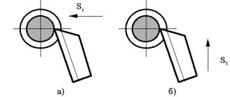
Depending on the nature of wear and the design of the equipment, sharpening is carried out on the front, back or both surfaces. The figure below shows all the surfaces of a turning tool
For standard cutters, as a rule, sharpening is used on all cutting surfaces. With minor wear, only the geometry of the rear surface is restored. Equipment for multi-cutting machines is restored only on the back surface, shaped – only on the front.
Standard sharpening order:
- Main back surface.
- Auxiliary back surface.
- Front surface.
- End radius.
The back surface sharpening parameters are shown in the figure below.
Figure (a) shows the back surface with one sharpening plane, figure (b) shows several. When brazing carbide inserts, the rear surface has three planes:
- along a chamfer with a height of not less than 1.5 mm at an angle a;
- along the remaining height at an angle a+3°;
- along the holder at an angle a+5°.
Sharpening the front surface of carbide cutters has many more varieties (see figure below).
Basic forms:
- Flat with a positive rake angle (a).
- Flat with a negative angle (b).
- Curvilinear with a negative angle (c).
- Flat with negative angle for roughing (d).
- Curved with a negative angle for stainless steels (d), and other materials (e)
During the sharpening process, it is necessary that the cutting edge of the tool being processed is located on the line of the center of the sharpening machine or below by no more than 3-5 mm. The direction of rotation of the circle should ensure that the plate is pressed against the holder, i.e., it should go towards the plate. During operation, a continuous supply of coolant is desirable. With periodic cooling, overstressing of the material structure and the appearance of microcracks is possible.
When sharpening, light pressure and constant movement along the surface of the wheel are required to form a smooth surface. After sharpening is completed, the geometry of the tool is checked using templates or special instruments.

