Normal corners (according to GOST 8908-81)
| 1st row | 2nd row | 3rd row | 1st row | 2nd row | 3rd row | 1st row | 2nd row | 3rd row |
| 0° | 10° | 70° | ||||||
| 0°15′ | 12° | 75° | ||||||
| 0°30′ | 15° | 80 | ||||||
| 0º45′ | 18 | 85 | ||||||
| 1° | 20 | 90° | ||||||
| 1°30′ | 22 | 100 | ||||||
| 2 | 25 | 110 | ||||||
| 2°30′ | 30 | 120 | ||||||
| 3 | 35 | 135 | ||||||
| 4 | 40 | 150 | ||||||
| 5 | 5 | 45 | 165 | |||||
| 6 | 50 | 180 | ||||||
| 7 | 55 | 270 | ||||||
| 8 | 60 | 360 | ||||||
| 9 | 65 |
The table does not apply to the angular dimensions of cones.
When choosing corners, the 1st row should be preferred to the 2nd, and the 2nd to the 3rd.
Regulatory requirements for slopes
When designing streets in populated areas, it is necessary to comply with the requirements for minimum and maximum longitudinal and transverse slopes. Slope values are given in ppm.
The transverse slope of the roadway of streets and squares is taken depending on the type of road surface:
— asphalt concrete and cement concrete – 15 ‰ – 25 ‰;
- prefabricated concrete and reinforced concrete slabs, cobblestone pavements - 20 ‰ - 25 ‰;
- crushed stone and gravel - 20 ‰ - 30 ‰;
- cobblestone pavements - 20 ‰ - 35 ‰.
During construction and reconstruction in cramped conditions, transverse slopes can be increased by 5 ‰.
Transverse and longitudinal slopes of parking spaces on parking lots and parking lots are accepted in the range from 5 ‰ to 40 ‰.
The transverse slope of parking spaces in parking lots adjacent directly to the roadway may be increased to 60 ‰.
Minimum longitudinal slope on streets with surface water drainage
on trays along the roadway, you should take:
- for asphalt concrete and cement concrete pavements - 4 ‰;
— for other types of coatings — 5 ‰.
If drainage trays are not provided along the roadway, then the value of the minimum longitudinal slope is not standardized, and it is ensured by transverse slopes.
Longitudinal slopes on sections of streets with traffic of buses, trolleybuses and trams should not exceed:
— 60 ‰ — with stopping points and curve radii in plan of 250 m or more;
— 40 ‰ — with stopping points and radii of curves in plan from 100 to 250 m;
— 40 ‰ — without stopping points with horizontal curve radii less than 100 m.
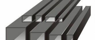
Normal tapers and cone angles (according to GOST 8593-81)
The standard applies to the tapers and taper angles of smooth conical elements of parts.
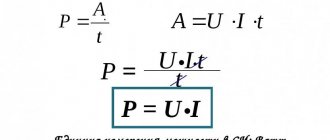
C = (D - d) / L = 2tg(α/2)
Cone designation | TaperC | Cone angle α | Slope angle α / 2 | ||||
| row 1 | row 2 | utl.ed. | glad | utl.ed. | glad | ||
| 1 : 500 | 1 : 500 | 0,0020000 | 6’52,5″ | 0,0000 | 3’26,25″ | 0,0010000 | |
| 1 :200 | 1 : 200 | 0,0050000 | 1711,3″ | 0,0050000 | 8’35,55″ | 0,0025000 | |
| 1 : 100 | 1 : 100 | 0,0100000 | 34’22,6″ | 0,0100000 | 17’11,3» | 0,0050000 | |
| 1 : 50 | 1 : 50 | 0,0200000 | 1°8’45,2″ | 0,0199996 | 34’22,6″ | 0,0099998 | |
| 1 : 30 | 1 :30 | 0,0333333 | 1°54’31,9″ | 0,0333304 | 57’17,45″ | 0,0166652 | |
| 1 : 20 | 1 :20 | 0,0500000 | 2°51’51,1» | 0,0499896 | 1°25’55,55″ | 0,0249948 | |
| 1 : 15 | 1 : 15 | 0,0666667 | 3°49’5,9″ | 0,0666420 | 1°54’32,95″ | 0,0333210 | |
| 1 : 12 | 1 : 12 | 0,0833333 | 4°4618,8″ | 0,0832852 | 2°23’19,4″ | 0,0416426 | |
| 1 : 10 | 1 : 10 | 0,1000000 | 5°43’29,3″ | 0,0999168 | 2°5144,65″ | 0,0499584 | |
| 1 : 8 | 1 : 8 | 0,1250000 | 7°9’9,6″ | 0,1248376 | 3°34’34,8″ | 0,0624188 | |
| 1 : 7 | 1 :7 | 0,1428571 | 8°10’16,4″ | 0,1426148 | 4°5’8,2″ | 0,0713074 | |
| 1 : 6 | 1 :6 | 0,1666667 | 9°31’38,2″ | 0,1662824 | 4°45’49,1» | 0,0831412 | |
| 1 : 5 | 1 :5 | 0,2000000 | 11°25’16,3″ | 0,1993374 | 5º42'38.15″ | 0,0996687 | |
| 1 : 4 | 1 : 4 | 0,2500000 | 14°15’0,1» | 0,2487100 | 7°7’30,05″ | 0,1243550 | |
| 1 : 3 | 1 : 3 | 0,3333333 | 18°55’28,7″ | 0,3302972 | 9°27’44,35″ | 0,1651486 | |
| 30° | 1:1,866025 | 0,5358985 | 30° | 0,5235988 | 15° | 0,2617994 | |
| 45e | 1:1,207107 | 0,8284269 | 45° | 0,7853982 | 22°30′ | 0,3926991 | |
| 60° | 1:0,866025 | 1,1547010 | 60° | 1,0471976 | 30° | 0,5235988 | |
| 75° | 1:0,651613 | 1,5346532 | 75° | 1,3089970 | 37°30′ | 0,6544985 | |
| 90° | 1:0,500000 | 2,0000000 | 90° | 1,5707964 | 45° | 0,7853982 | |
| 120° | 1:0,288675 | 3,4641032 | 120° | 2,0943952 | 60° | 1,0471976 | |
Note.
The taper or cone angle values indicated in the “Cone designation” column are taken as the initial values when calculating other values given in the table.
When selecting tapers or taper angles, Row 1 should be preferred to Row 2.
Constructing slope and taper
Constructing slope and taper is quite simple, only in some cases serious problems may arise. Among the main recommendations we note the following:
- Normal tapers are the easiest to display, since their main parameters are standardized.
- In most cases, the input information when creating a taper is the larger and smaller diameter, as well as an intermediate value if there is a difference. That is why they are laid down first, taking into account their relative positions, after which the connection is made. The line that is laid between the two diameters and determines the angle of inclination.
- With the angle of inclination during construction, everything arises somewhat differently. As previously noted, to display such a figure requires the construction of additional lines, which can be left or removed. The task can be significantly simplified by using tools that allow you to determine the angle of inclination, for example, a protractor.
Today, when computers have become very widespread, drawings are also displayed using special programs. Their advantages include the following:
- Ease of operation. The software is created in order to significantly simplify the task of creating a drawing. Examples include tracking angles, sizes, mirroring capabilities, and much more. In this case, you do not need to have a large set of different tools; it is enough to purchase the required program and select a suitable computer, as well as a printing device. Due to the advent of software of this type, the construction of tapers and other surfaces has been significantly simplified. That is why construction takes much less time than before.
- High construction accuracy, which is required if the scale is respected. The computer does not allow errors; if all information is entered accurately, there will be no deviations. This point is most relevant in the case of creating projects for the manufacture of various complex products, when it is almost impossible to display all the main dimensions.
- There is no possibility of making a mistake due to which the lines will be erased. The fingerboard can rub against the surface, and the created drawing in a single copy will not last for a long period. When using the electronic version, all information is displayed in paint, which, after complete drying, no longer reacts to environmental influences.
- It is possible to edit at any stage of the design. In some cases, it is necessary to make changes to the drawing being developed from time to time due to identified errors and many other reasons. If special software is used, this can be done at almost every design stage.
- Convenient project storage and transfer. An electronic drawing does not have to be printed; it can be sent electronically, and printing is carried out only when necessary. In this case, all information can be copied many times.
The construction procedure when using such programs is characterized by a fairly large number of features that need to be taken into account. The main ones are the following:
- The program automatically displays the angle when constructing inclined lines. The calculations carried out in this case allow the construction to be carried out even if there is no information about the large or small intermediate diameter. Of course, information is required regarding the position of the diameters relative to each other.
- It is possible to use additional tools, for example, a snap to build a normal taper. Due to this, the task at hand is significantly simplified and the procedure itself is accelerated. When drawing by hand, you have to use special tools to control such parameters.
- The length of all lines is entered numerically, thereby achieving high accuracy. An error can only be made when using a low-quality device for displaying graphic information.
- It is possible to measure all indicators when using the appropriate tools.
- To display standards, appropriate tools are used, which also significantly simplify the task. If the program has the appropriate settings, then it is enough to select the required tool and indicate which dimensions should be displayed. There is no need to know the standards associated with displaying arrows and other lines.
There are several common programs that can be used to construct a wide variety of shapes. Their use is considered standard today. The work requires certain skills, as well as knowledge of established standards for displaying various planes and sizes. Don't forget that the software in question is just a tool, all the work is done by an engineer.
The concept of taper is found in a fairly large number of different technical literature. An example is the mechanical engineering area, in which tapered shafts and other products are common. In practice, the production of such products can create quite a large number of problems, since maintaining a given angle is not easy.
Taper of outer and inner tapers with threaded hole
| Designation of cone size | Taper | Cone angle 2α |
| AT 7 | 1 : 19,212 = 0,05205 | 2°58’54» |
| B10; B12 | 1 : 20,047 = 0,4988 | 2°51’26» |
| B16; B18 | 1 : 20, = 0,04995 | 2°51’41» |
| B22; B24 | 1 : 19,922 = 0,05020 | 2°52’32» |
| B32 | 1 : 19,954 = 0,05194 | 2º58'31" |
| B45 | 1 : 19,002 = 0,05263 | 3°00’53» |
The cone angle 2α is calculated from the taper value with rounding 1"
Formula for determining taper
You can independently calculate the taper by using various formulas. It is worth considering that in most cases the indicator is indicated in degrees, but it can also be expressed as a percentage - it all depends on the specific case. The calculation algorithm is as follows:
- K=Dd/l=2tgf=2i. This formula is characterized by the fact that the taper is characterized by a double slope. It is based on obtaining the value of the major and minor diameters, as well as the distance between them. In addition, the angle is determined.
- Tgf=D/2L. In this case, the length of the segment that connects the large and small diameters, as well as the indicator of the large diameter, is required.
- F=arctgf. This formula is used to convert the indicator to degrees. Today, in most cases, degrees are used, since they are easier to maintain when directly carrying out constructions. As for percentages, they are often indicated to enable the calculation of one of the diameters. For example, if the ratio is 20% and a smaller diameter is given, then you can quickly calculate the larger one.
As previously noted, the 1:5 taper and other indicators are standardized. For this, GOST 8593-81 is used.
Calculations are not shown in the drawing. As a rule, an additional explanatory note is created for this purpose. It is quite simple to calculate the basic parameters; in some cases, a drawing is constructed, after which the angle value and other indicators are measured.
Recommended dimensions of the center hole of a shortened cone
Dimensions, mm
Center holes for Morse tapers B12, B18, B24 and B45 are P-shaped according to GOST 14034-74. It is allowed to manufacture a center hole with the dimensions indicated in the table.
Morse cone notation | d2 | d3 | d4 | L |
| AT 12 | M6 | 8,0 | 8,5 | 16 |
| B18 | M10 | 12,5 | 13,2 | 24 |
| B24 | M12 | 15,0 | 17,0 | 28 |
| B32 B45 | M16 M20 | 20,0 26,0 | 22,0 30,0 | 32 40 |
Converting fractions
1
To convert a fraction to a decimal, simply divide the numerator by the denominator.
Remember that the line between the numerator and denominator represents the division operation. That is, the fraction x/y is “x” divided by “y”.[7]
- For example: fraction 4/8 = 0.5.
2
Decide on the number of characters (digits) after the decimal point.
Many numbers are divisible by an integer. When dividing such numbers, leave a certain number of decimal places. In most cases, you can leave two places after the decimal point. Remember the rounding rules: if after the sign being rounded there is a number from 5 to 9, then the number being rounded is increased by 1; otherwise, the rounded figure does not change. For example, the fraction 0.145 is rounded to 0.15.
- For example, 5/17 = 0.2941176470588 ...
Here the rounded fraction is 0.29.
3
Divide the numerator by the denominator, and then multiply the result by 100 to get a percentage.
Divide the numerator of a common fraction by its denominator, multiply the resulting result by 100, add a percent sign (%) to the answer, and you get percentages.[8]
- For example, given the fraction 4/8. Divide 4 by 8 to get 0.50. Multiply 0.50 by 100 to get 50. Add a percent sign to get the final answer: 50%.
Additional examples: 3/10 = 0.30 * 100 = 30%
- 5/8 = 0,625 * 100 = 62,5%
Dimensions, mm
Inner cones
For cones with foot
For cones with threaded hole
| Cone | Metric | Morse | Metric | |||||||||||
| Cone designation | 4 | 6 | 0 | 1 | 2 | 3 | 4 | 5 | 6 | 80 | 100 | 120 | 160 | 200 |
| Taper | 1 : 20 = 0,05 | 1 : 19,212 = 0,05205 | 1 : 20,047 = 0,04988 | 1 : 20,020 = 0,04995 | 1 : 19,922 = 0,05 | 1 : 19,254 = 0,05194 | 1 : 19,002 = 0,05263 | 1 : 19,180 = 0,05214 | 1 : 20 = 0,05 | |||||
| D | 4 | 6 | 9,045 | 12,065 | 17,780 | 23,825 | 31,267 | 44,399 | 63,348 | 80 | 100 | 120 | 160 | 200 |
| d5 | 3 | 4,6 | 6,7 | 9,7 | 14,9 | 20,2 | 26,5 | 38,2 | 54,6 | 71,5 | 90 | 108,5 | 145,5 | 182,5 |
| d6 | — | — | — | 7 | 11,5 | 14 | 18 | 23 | 27 | 33 | 39 | 52 | ||
| l5 min | 25 | 34 | 52 | 56 | 67 | 84 | 107 | 135 | 188 | 202 | 240 | 276 | 350 | 424 |
| l6 | 21 | 29 | 49 | 52 | 62 | 78 | 98 | 125 | 177 | 186 | 220 | 254 | 321 | 388 |
| g | 2,2 | 3,2 | 3,9 | 5,2 | 6,3 | 7,9 | 11,9 | 15,9 | 19 | 26 | 32 | 38 | 50 | 62 |
| h | 8 | 12 | 15 | 19 | 22 | 27 | 32 | 38 | 47 | 52 | 60 | 70 | 90 | 110 |
1. GOST provides dimensions for external tool cones.
2. Maximum deviations of cone sizes and shape tolerances according to GOST 2848-75.
Converting Decimals
1
Multiply the decimal by 100 to get a percentage.
Or simply move the decimal point two places to the right. Remember that a percentage is a fraction of 100, so multiplying a decimal by 100 will give you that “fraction of 100.” After multiplying, do not forget to add the percent sign (%).[3] For example: 0.32 = 32%; 0.07 = 7%; 1.25 = 125%; 0.083 = 8.3%
2
Convert the trailing decimal to a fraction.
The final decimal after the decimal point has a limited number of digits. Move the decimal point a number of places to the right equal to the number of digits after the decimal point. The resulting number is the numerator of the common fraction. In the denominator, write 1 with the number of zeros equal to the number of digits after the decimal point. Then you need to simplify the resulting fraction (if, of course, this is possible).[4]
- For example, the decimal fraction 0.32 has two digits after the decimal point. Move the decimal point two places to the right, and write 100 in the denominator; thus 0.32 = 32/100. Divide both the numerator and denominator by 4 and you get: 36/100 = 9/25.
Another example: in the decimal fraction 0.8 there is one digit after the decimal point. Move the decimal point one place to the right, and write 10 in the denominator; thus 0.8 = 8/10. Divide both the numerator and denominator by 2 and you get: 8/10 = 4/5.
- To check your answer, simply divide the numerator by the denominator - the result should be equal to the original decimal fraction. In our example: 8/25 = 0.32.
3
Convert a periodic fraction to a common fraction.
A periodic fraction after the decimal point has a periodically repeating group of digits. For example, in the fraction 0.131313... two digits (13) are periodically repeated. Determine how many digits are repeated periodically, and then multiply the periodic fraction by 10n, where n is the number of digits that repeat periodically.[5]
- In our example, 0.131313... multiply by 100 (10 to the second power) and get 13.131313...
To find the numerator (top number) of a common fraction, subtract the repeating group of digits from the resulting fraction. In our example: 13.131313… – 0.131313… = 13, that is, the numerator is 13.[6]
- To find the denominator (bottom number) from the number you multiplied the original periodic fraction by, subtract 1. For example, you multiplied the original fraction 0.131313... by 100, so the denominator is 100 – 1 = 99.
- In our example: 0.131313...= 13/99.
- Additional examples: 0.333... = 3/9
- 0,123123123… = 123/999
- 0,142857142857… = 142857/999999
- If necessary, simplify the fraction, for example, 142857/999999 = 1/7.
Internal and external cones with a taper of 7:24 (according to GOST 15945-82)
Dimensions, mm
Example of cone 25 designation:
Cone 25 GOST 15945-82
Cone designation | D | L* (informative) |
| 10 | 15,87 | 21,8 |
| 15 | 19,05 | 26,9 |
| 25 | 25,40 | 39,8 |
| 30 | 31,75 | 49,2 |
| 35 | 38,10 | 57,2 |
| 40 | 44,45 | 65,6 |
| 45 | 57,15 | 84,8 |
| 50 | 69,85 | 103,7 |
| 55 | 88,90 | 131,6 |
| 60 | 107,95 | 163,7 |
| 65 | 133,35 | 200,0 |
| 70 | 165,10 | 247,5 |
| 75 | 203,20 | 305,8 |
| 80 | 254,00 | 390,8 |
Converting percentages
1
Move the decimal point two places to the left.
This will convert the percentage to a decimal. If a percentage number does not have a decimal point, feel free to place it after the last digit, for example, 75% = 75.0%. Move the decimal point two places to the left to convert a percentage to a decimal—this is the same as dividing a number by 100. For example:[1]
- 75% = 0,75
3,1% = 0,031
- 0,5% = 0,005
2
Express percentages as a fraction of 100.
You can write percentages as a fraction with a denominator of 100, with the numerator being the percentage number. Then you need to simplify the resulting fraction (if, of course, this is possible).
- For example, 36% = 36/100.
To simplify a fraction, find the largest number that divides both the numerator and denominator. In our example, this number is the number 4.
- Divide both the numerator and denominator by the number you find. In our example you will get: 36/100 = 9/25.
- To check your answer, divide the numerator by the denominator: 9 ÷ 25 = 0.36, and then multiply the result by 100: 0.36 x 100 = 36%. The resulting number must be equal to the percentage number.
3
Get rid of the percent sign.
By converting percentages to a fraction or decimal, the percent sign (%) is no longer needed. Remember that a percentage is a fraction of 100, so if you forget to remove the percent sign after converting to a decimal, it means your answer is a fraction of 100.[2]
Dimensions and tolerances of the angles of external and internal cones
*Size for reference.
** Z - basal distance of the cone is specified in the standards for specific products
1 - main plane; 2 - base plane
Cone designations | D | d | Lcalculation | Angle tolerance, µm, cone ATD according to GOST 8908 | ||||
| 3 | 4 | 5 | 6 | 7 | ||||
| 30 | 31,75 | 17,750 | 48 | 2,5 | 4 | 6 | 10 | 15 |
| 35 | 38,10 | 21,767 | 56 | 2,5 | 4 | 6 | 10 | 15 |
| 40 | 44,45 | 25,492 | 65 | 3,0 | 5 | 8 | 12 | 20 |
| 45 | 57,15 | 32,942 | 83 | 3,0 | 5 | 8 | 12 | 20 |
| 50 | 69,85 | 40,100 | 102 | 4,0 | 6 | 10 | 16 | 25 |
| 55 | 88,90 | 54,858 | 127 | 4,0 | 6 | 10 | 16 | 25 |
| 60 | 107,95 | 60,700 | 162 | 5,0 | 8 | 12 | 20 | 30 |
| 65 | 133,35 | 74,433 | 202 | 5,0 | 8 | 12 | 20 | 30 |
| 70 | 165,10 | 92,183 | 250 | 6,0 | 10 | 16 | 25 | 40 |
| 75 | 203,20 | 113,658 | 307 | 6,0 | 10 | 16 | 25 | 40 |
| 80 | 254,00 | 138,208 | 394 | 8,0 | 12 | 20 | 30 | 50 |
Symbol of cones according to GOST 15945 with the addition of the degree of accuracy of the cone:
Cone 50 AT5 GOST 15945-82
The maximum deviations of the basal distance of the Z cone should be selected from the following range: ± 0.4; ±0.2; ±0.1; ± 0.05mm.
Continuation of the table. 10
Handrails for ramp
- At the beginning and end, the handrails should be 300 mm longer and have a rounded shape.
- The top handrail is located at a height of 900 mm.
- The distance between handrails is 900-1000 mm.
- The railings must be round in cross-section with a diameter of 30 to 50 mm.
- The beginning and end are marked with warning stripes.
- The bottom handrail should be at a height of 700 mm.
- Sideboards with a height of at least 0.05 m should be installed along the longitudinal edges of the ramp.
- The ramp coating must have an anti-slip effect.
- The minimum distance from a smooth wall is 45 mm, from an uneven wall 60 mm.
- The handrails on the inside should not be interrupted.
- Handrails are made of metal and are installed on both sides of the inclined platform.
If the ramp initially meets all construction parameters, then it can be equipped with the necessary additional devices if they are not available:
- Support handrails. The distance between the handrails of a one-way ramp should be within 0.9-1.0 m so that a wheelchair user can pull himself up on them. Also, for convenience and safety of grip, the handrails should have a rounded shape and protrude 300 mm from the edge.
- Contrasting tactile markings (for blind and visually impaired people). Markings should be used to mark the handrails themselves and the underlying surface. Tactile stickers can be placed on the inside of the handrails to indicate the beginning and end of the obstacle.
If the ramp does not initially meet the design parameters in accordance with the codes of practice, then it should be dismantled and an accessible ramp installed in its place.
Adaptation questions Car parking for the visually impaired Adaptation of sidewalks for the blind Adaptation of stairs for the visually impaired Adaptation of the entrance area Adaptation of the hall in the room Adaptation of the bathroom for the blind Adaptation of elevators for the visually impaired