In order to connect parts together using rivets, pins, bolts, studs and screws, holes are usually required. For through holes for fasteners , there is a standard that recommends using nominal size values.
GOST 11284 − 75
| Through holes for fasteners | |||
| d | d1 | ||
| 1st row | 2nd row | 3rd row | |
| 1,0 | 1,1 | 1,2 | 1,3 |
| 1,2 | 1,3 | 1,4 | 1,5 |
| 1,4 | 1,5 | 1,6 | 1,8 |
| 1,6 | 1,7 | 1,8 | 2,0 |
| 1,8 | 2,0 | 2,1 | 2,2 |
| 2,0 | 2,2 | 2,4 | 2,6 |
| 2,5 | 2,7 | 2,9 | 3,1 |
| 3,0 | 3,2 | 3,4 | 3,6 |
| 3,5 | 3,7 | 3,9 | 4,2 |
| 4,0 | 4,3 | 4,5 | 4,8 |
| 4,5 | 4,8 | 5,0 | 5,3 |
| 5,0 | 5,3 | 5,5 | 5,8 |
| 6,0 | 6,4 | 6,6 | 7,0 |
| 7,0 | 7,4 | 7,6 | 8,0 |
| 8,0 | 8,4 | 9,0 | 10,0 |
| 10,0 | 10,5 | 11,0 | 12,0 |
| 12,0 | 13,0 | 14,0 (13,5) | 15,0 (14,5) |
| 14,0 | 15,0 | 16,0 (15,5) | 17,0 (16,5) |
| 16,0 | 17,0 | 18,0 (17,5) | 19,0 (18,5) |
| 18,0 | 19,0 | 20,0 | 21,0 |
| 20,0 | 21,0 | 22,0 | 24,0 |
| 22,0 | 23,0 | 24,0 | 26,0 |
| 24,0 | 25,0 | 26,0 | 28,0 |
| 27,0 | 28,0 | 30,0 | 32,0 |
| 30,0 | 31,0 | 33,0 | 35,0 |
| 33,0 | 34,0 | 36,0 | 38,0 |
| 36,0 | 37,0 | 39,0 | 42,0 |
| 39,0 | 40,0 | 42,0 | 45,0 |
| 42,0 | 43,0 | 45,0 | 48,0 |
| 45,0 | 46,0 | 48,0 | 52,0 |
| 48,0 | 50,0 | 52,0 | 56,0 |
| 52,0 | 54,0 | 56,0 | 62,0 |
| 56 | 58 | 62 | 66 |
| 60 | 62 | 66 | 70 |
| 64 | 66 | 70 | 74 |
| 68 | 70 | 74 | 78 |
| 72 | 74 | 78 | 82 |
| 76 | 78 | 82 | 86 |
| 80 | 82 | 86 | 91 |
| 85 | 87 | 91 | 96 |
| 90 | 93 | 96 | 101 |
| 95 | 98 | 101 | 107 |
| 100 | 104 | 107 | 112 |
| 105 | 109 | 112 | 117 |
| 110 | 114 | 117 | 122 |
| 115 | 119 | 122 | 127 |
| 120 | 124 | 127 | 132 |
| 125 | 129 | 132 | 137 |
| 130 | 134 | 137 | 144 |
| 140 | 144 | 147 | 155 |
| 150 | 155 | 158 | 165 |
| 160 | 165 | 168 | 175 |
Part connections
All connections of various parts that are used in mechanical engineering and instrument making are divided into movable and fixed. In this case, those that ensure the movement of parts relative to each other are considered movable, and those that require rigid fastening between them are considered stationary.
The possibility of repeated assembly and disassembly of components and assemblies of machines and equipment is ensured by detachable connections. These include threaded, splined, keyed, profile, pin and terminal.
Unlike detachable ones, permanent connections cannot be disassembled without damaging the parts. These include welded, adhesive, soldered, riveted joints, as well as joints with guaranteed interference. In technology, connections play an extremely important role, and many malfunctions in the operation of machines and equipment, as well as accidents, often occur because their parts were poorly connected to each other.
THROUGH HOLES FOR FASTENERS DIMENSIONS Through holes for fasteners. Dimensions
Standards → GOST 11284-75: Through holes for fasteners. Dimensions.STATE STANDARD OF THE USSR UNION
GOST 11284-75 Instead of GOST 11284-65
By Decree of the State Committee of Standards of the Council of Ministers of the USSR dated November 14, 1975 No. 3134, the validity period was established from 01/01/77 to 01/01/87
1. This standard establishes the dimensions of through holes for bolts, screws, studs and rivets with rod diameters from 1.0 to 160 mm, used to connect parts with gaps.
The standard fully complies with the CMEA standardization recommendation PC 107-72 and the ISO recommendation P-273.
2. The dimensions of through holes must correspond to those indicated in the table.
Diameters of fastener rods d
| Diameters of through holes d1 | Diameters of fastener rods d | Diameters of through holes d1 | |||||
| 1st row | 2nd row | 3rd row | 1st row | 2nd row | 3rd row | ||
| 1,0 | 1,2 | 1,3 | — | 2,5 | 2,7 | 2,9 | 3,1 |
| 1,2 | 1,4 | 1,5 | — | 3,0 | 3,2 | 3,4 | 3,6 |
| 1,4 | 1,6 | 1,7 | — | 4,0 | 4,3 | 4,5 | 4,8 |
| 1,6 | 1,7 | 1,8 | 2,0 | 5,0 | 5,3 | 5,5 | 5,8 |
| 2.0 | 2,2 | 2,4 | 2,6 | 6,0 | 6,4 | 6,6 | 7,0 |
| Diameters of fastener rods d | Diameters of through holes d1 | Diameters of fastener rods d | Diameters of through holes d1 | ||||
| 1st row | 2nd row | 3rd row | 1st row | 2nd row | 3rd row | ||
| 7,0 | 7,4 | 7,6 | 8,0 | 56 | 58 | 62 | 66 |
| 8,0 | 8,4 | 9,0 | 10,0 | 60 | 62 | 66 | 70 |
| 10,0 | 10,5 | 11,0 | 12,0 | 64 | 66 | 70 | 74 |
| 12,0 | 13,0 | 14,0 | 15,0 | 68 | 70 | 74 | 78 |
| 14,0 | 15,0 | 16,0 | 17,0 | 72 | 74 | 78 | 82 |
| 16,0 | 17,0 | 18,0 | 19,0 | 76 | 78 | 82 | 86 |
| 18,0 | 19,0 | 20,0 | 21,0 | 80 | 82 | 86 | 91 |
| 20,0 | 21,0 | 22,0 | 24,0 | 85 | 87 | 91 | 96 |
| 22,0 | 23,0 | 24,0 | 26,0 | 90 | 93 | 96 | 101 |
| 24,0 | 25,0 | 26,0 | 28,0 | 95 | 98 | 101 | 107 |
| 27,0 | 28,0 | 30,0 | 32,0 | 100 | 104 | 107 | 112 |
| 30,0 | 31,0 | 33,0 | 35,0 | 105 | 109 | 112 | 117 |
| 33,0 | 34,0 | 36,0 | 38,0 | 110 | 114 | 117 | 122 |
| 36.0 | 37,0 | 39,0 | 42,0 | 115 | 119 | 122 | 127 |
| 39,0 | 40,0 | 42,0 | 45,0 | 120 | 124 | 127 | 132 |
| 42,0 | 43,0 | 45,0 | 48,0 | 125 | 129 | 132 | 137 |
| 45,0 | 46,0 | 48,0 | 52,0 | 130 | 134 | 137 | 144 |
| 48,0 | 50,0 | 52,0 | 56,0 | 140 | 144 | 147 | 155 |
| 52,0 | 54,0 | 56,0 | 62,0 | 150 | 155 | 158 | 165 |
| 160 | 165 | 168 | 175 | ||||
Notes:
1. The 3rd row of holes is not allowed to be used for rivet connections
2. Recommendations for selecting rows of through holes are given in the appendix.
3. Limit deviations of hole diameters:
a) for the 1st row - according to H12; b) for the 2nd and 3rd rows - according to H14.
APPENDIX Recommended
RECOMMENDATIONS FOR SELECTING ROWS OF THROUGH HOLES
1. When independently processing the holes of each part of the connection with the distance between the axes of the most distant holes less than 500 mm, for connections for which only assembly requirements are imposed, it is recommended to select rows of through holes according to the table below.
Connection type
| Number and location of holes | Hole forming method | Connection type | Recommended number of through holes |
| Any number of holes and any location | Machining holes for jigs | I and II | 1st row |
| a - holes are located in one row and copied relative to the hole axis or reference plane | Punching holes with high precision dies, injection molding and high precision lost wax casting | I | |
| II | 2nd row | ||
| b - holes (up to four in number) are located in two rows and coordinated relative to their axes | Processing holes according to markings, punching with stamps of normal accuracy, casting of normal accuracy | I | 1st row |
| II | 2nd row | ||
| a—holes are located in two or more rows and coordinated relative to the axes of the holes or base planes b—holes are located in a circle | Punching holes with high-precision dies, iodine injection molding and high-precision lost-wax casting | I and II | 2nd row |
| Processing holes according to markings, punching with stamps of normal accuracy, casting of normal accuracy | I | 3rd row |
2. For connections that are subject to assembly requirements and additional requirements to ensure a certain degree of relative movement of parts, as well as for connections that are subject to only assembly requirements, but with distances between the axes of the most distant holes in the parts of 500 mm or more, it is allowed to accept more rough (compared to those recommended in the table) rows of through holes.
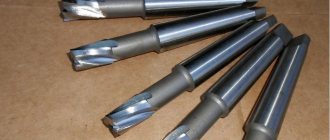
3. When processing holes in joint parts together (for rivet and permanent bolted connections), the nominal diameter of the through hole is recommended to be taken equal to the largest limiting size of the diameter of the fastener rod. In this case, the holes must be countersunk to a size corresponding to the transition radius between the head and the rod.
Change No. 1 GOST 11284-75. Through holes for fasteners. Dimensions.
By Decree of the USSR State Committee for Standards dated 81 12 03 No. 5218, the introduction date was set from 82 01 01
On the cover and first page, the standard designation should be supplemented with the following designation: (ST SEV 2515-80).
Clause 1. The second paragraph should be stated in a new edition:
“The standard fully complies with ST SEV 2515-80>.
Clause 2 shall be stated in a new edition (except for the table and note):
"2. The dimensions of through holes must correspond to those indicated in the drawing and table.
Table. Replace size designation: d1 with dh; supplement the table with the diameters of the fastener rods d - 1.8; 3.5; 4.5 mm with corresponding dh; column “Diameters of through holes dh” for diameters d of fasteners 1.0; 1.2; 1.4; 12.0; 14.0 and 16.0 mm shall be stated in a new edition:
| Diameters of fastener rods d | Diameters of through holes, dh | ||
| 1st row | 2nd row | 3rd row | |
| 1,0 | 1,1 | 1,2 | 1,3 |
| 1,2 | 1,3 | 1,4 | 1,5 |
| 1,4 | 1,5 | 1,6 | 1,8 |
| 1,8 | 2,0 | 2,1 | 2,2 |
| 3,5 | 3,7 | 3,9 | 4,2 |
| 4,5 | 4,8 | 5,0 | 5,3 |
| 12,0 | 13,0 | 14,0 (13,5) | 15,0 (14,5) |
| 14,0 | 15,0 | 16,0 (15,5) | 17,0 (16,5) |
| 16. 0 | 17,0 | 18,0 (17,5) | 19,0 (18,5) |
supplement the table with note - 3:
"3. Dimensions in brackets are not recommended.”
Clause 3 shall be stated in a new wording:
"3. Maximum deviations of hole diameters:
for the 1st row - H12; for the 2nd row - H13; for the 3rd row - H14."
The standard should be supplemented with POINT - 4:
"4. If necessary, eliminate the contact of the hole edge with the radius under the head of the fastener; It is recommended to countersink the hole.”
INTERNATIONAL SYSTEM OF UNITS (SI)
| Magnitude | Unit | ||
| Name | Designation | ||
| Russian | international | ||
| BASIC UNITS | |||
| LENGTH | meter | m | m |
| WEIGHT | kilogram | kg | kg |
| TIME | second | With | s |
| POWER OF ELECTRIC TONE | ampere | A | A |
| THERMODYNAMIC TEMPERATURE KELVIN | kelvin | TO | TO |
| SIPA SVETA | candela | KD | CD |
| ADDITIONAL UNITS | |||
| Flat angle | radian | glad | rad |
| Solid angle | steradian | Wed | sr |
| DERIVATIVE UNITS | |||
| Square | square meter | m2 | m2 |
| Volume, capacity | cubic meter | m3 | m3 |
| Density | kilogram per cubic meter | kg/m3 | kg/m3 |
| Speed | meter per second | m/s | m/s |
| Angular velocity | radians per second | rad/s | rad/s |
| Force; gravity (weight) | newton | N | N |
| Pressure; mechanical stress | pascal | Pa | Pa |
| Job; energy; quantity of heat | joule | J | J |
| Power; heat flow | watt | VT | W |
| Amount of electricity; electric charge | pendant | Cl | WITH |
| Electrical voltage, electrical potential, electrical potential difference, electromotive force | volt | IN | V |
| Electrical resistance | ohm | Ohm | |
| Electrical conductivity | Siemens | Cm | S |
| Electrical capacity | farad | F | F |
| Magnetic flux | webes* | Wb | Wb |
| Inductance, mutual inductance. | Henry | G | H |
| Specific heat | joule per kilogram Kelvin | J/(kg*K) | J/(kg*K) |
| Thermal conductivity | Watt per meter kelvin | W/(m*K) | W/(m*K) |
| Light flow | lumen | lm | lm |
| Brightness | candela per square meter | cd/m2 | cd/m2 |
| Illumination | luxury | OK | lx |
FACTORS AND PRESCRIPTS FOR FORMING DECIMAL MULTIPLES AND FROM FROM UNITS AND THEIR NAMES
| Multiplier by which one is multiplied | Console | Designation | Multiplier by which one is multiplied | Console | Designation | ||
| Russian | international | Russian | international | ||||
| 1012 | tera | T | T | 10-2 | (centi) | With | c |
| 109 | giga | G | G | 10-3 | Milli | m | m |
| 106 | mega | M | M | 10-6 | micro | mk | |
| 103 | kilo | To | k | 10-9 | nano | n | n |
| 102 | (hecto) | G | h | 10-12 | pico | P | p |
| 101 | (deck) | Yes | da | 10-15 | femto | f | f |
| 10-1 | (deci) | D | d | 10-18 | atto | A | A |
| Note: prefixes are indicated in parentheses that can only be used in the names of multiples and submultiples that have already become widespread (for example, hectare, deciliter, decimeter, centimeter) | |||||||
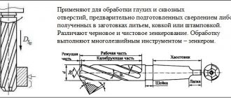
Hole Machining Methods
The holes differ from each other not only in diameter, but also in the processing method, and are divided into several types.
1) Mounting holes. They are most often made on drilling machines and in terms of processing accuracy they correspond to the eleventh and twelfth qualifications.
2) Smooth and stepped holes of parts having the shape of bodies of revolution. In most cases, they are made on lathes by drilling, reaming, countersinking or boring.
3) Critical openings of body parts. They are manufactured using both universal and specialized equipment and correspond to the seventh qualification and higher.
4) Deep holes having more than five times the length to diameter ratio. They are manufactured on specialized equipment.
5) Shaped and conical holes. They are manufactured using tools with curved or conical cutting edges, as well as copying and boring methods.
6) Profile holes (having a cross-section other than round). They are made by chiseling, stitching or drawing.
For which materials are the values indicated in the table?
The indicated hole diameters provide cutting of metric threads in:
- gray cast iron
- carbon steels of ordinary quality
- quality structural steels
- alloyed structural steels
- high alloy steels
- corrosion-resistant, heat-resistant and heat-resistant alloys
- heat-resistant steels
- aluminum casting alloys
- copper
A complete list of threads and diameters can be found in GOST 19257-73 - an official technical document with all the nuances and details.
Before you begin, we recommend that you read the practical tips in the article How to properly cut a thread with a tap. And there you can find suitable coolant for different materials.
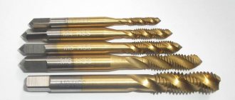
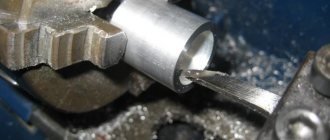
Cutting technique
Using a hand tap, cutting can be carried out following the following steps:
- drill an opening for a thread of the appropriate diameter and depth;
- countersink it;
- secure the tap in the holder or driver;
- align it perpendicular to the working cavity in which cutting will be carried out;
- screw the tap with light pressure clockwise into the hole prepared in advance for threading;
- Turn the tap back every half turn to cut off the chips.
Thread system
To cool and lubricate surfaces during the cutting process, it is important to use lubricants: machine oil, drying oil, kerosene and the like. Incorrectly selected lubricant can lead to poor cutting results.
Table of recommended threaded hole diameters, mm
| ⌀ thread | Step | ⌀ drills | Step | ⌀ drills | Step | ⌀ drills | Step | ⌀ drills | Step | ⌀ drills | Step | ⌀ drills |
| 2 | 0.4 | 1.6 | 0.25 | 1.75 | ||||||||
| 3 | 0.5 | 2.5 | 0.35 | 2.65 | ||||||||
| 4 | 0.7 | 3.3 | 0.5 | 3.5 | ||||||||
| 5 | 0.8 | 4.2 | 0.5 | 4.5 | ||||||||
| 6 | 1 | 5 | 0.75 | 5.2 | 0.5 | 5.5 | ||||||
| 7 | 1 | 6 | 0.75 | 6.2 | 0.5 | 6.5 | ||||||
| 8 | 1.25 | 6.7 | 1 | 7 | 0.75 | 7.2 | 0.5 | 7.5 | ||||
| 9 | 1.25 | 7.7 | 1 | 8 | 0.75 | 7.2 | 0.5 | 8.5 | ||||
| 10 | 1.5 | 8.5 | 1.25 | 8.7 | 1 | 9 | 0.75 | 9.2 | 0.5 | 9.5 | ||
| 11 | 1.5 | 9.5 | 1 | 10 | 0.75 | 10.2 | 0.5 | 10.5 | ||||
| 12 | 1.75 | 10.2 | 1.5 | 10.5 | 1.25 | 10.7 | 1 | 11 | 0.75 | 11.2 | 0.5 | 11.5 |
| 14 | 2 | 12 | 1.5 | 12.5 | 1.25 | 12.6 | 1 | 13 | 0.75 | 13.2 | 0.5 | 13.5 |
| 16 | 2 | 14 | 1.5 | 14.5 | 1 | 15 | 0.75 | 15.2 | 0.5 | 15.5 | ||
| 18 | 2.5 | 15.4 | 2 | 16 | 1.5 | 16.5 | 1 | 17 | 0.75 | 17.2 | 0.5 | 17.5 |
| 20 | 2.5 | 17.4 | 2 | 18 | 1.5 | 18.5 | 1 | 19 | 0.75 | 19.2 | 0.5 | 19.5 |
| 22 | 2.5 | 19.4 | 2 | 20 | 1.5 | 20.5 | 1 | 21 | 0.75 | 21.2 | 0.5 | 21.5 |
| 24 | 3 | 20.8 | 2 | 22 | 1.5 | 22.5 | 1 | 23 | 0.75 | 23.2 | ||
| 27 | 3 | 23.9 | 2 | 25 | 1.5 | 25.5 | 1 | 26 | 0.75 | 26.2 | ||
| 30 | 3.5 | 26.4 | 3 | 26.9 | 2 | 28 | 1.5 | 28.5 | 1 | 29 | 0.75 | 29.2 |
| 33 | 3.5 | 29.4 | 3 | 29.9 | 2 | 31 | 1.5 | 31.5 | 1 | 32 | 0.75 | 32.2 |
| 36 | 4 | 31.9 | 3 | 32.9 | 2 | 34 | 1.5 | 34.5 | 1 | 35 | ||
| 39 | 4 | 34.9 | 3 | 35.9 | 2 | 37 | 1.5 | 37.5 | 1 | 38 | ||
| 42 | 4.5 | 37.4 | 4 | 37.9 | 3 | 38.9 | 2 | 34 | 1.5 | 40.5 | 1 | 41 |
| 45 | 4.5 | 40.4 | 4 | 40.9 | 3 | 41.9 | 2 | 43 | 1.5 | 43.5 | 1 | 44 |
| 48 | 5 | 42.8 | 4 | 43.9 | 3 | 44.9 | 2 | 46 | 1.5 | 46.5 | 1 | 47 |
The table shows that the diameter of the drill is less than the outer diameter of the thread by approximately the pitch, that is:
In practice, many home craftsmen constantly use this simple formula when it is not possible to refer to the table.
For example, for M10x1.5
: Dot = 10 – 1.5 = 8.5 mm
This method is quite acceptable when thread cutting is performed manually in a metal workshop. If the planned threaded connection is not subject to serious loads during operation, then a slight increase in the size of the hole can be allowed. In assembly production, where high precision of thread profile dimensions is required, any deviations are unacceptable. The diameters of the threaded holes with the tolerance range are established by GOST 19257-73.
Comment for Yuri Barinov: a tap broken in a hole can be burned out with a welding machine by taking the leads from the battery, heating them several times and cooling them in water, it will fall out on its own piece by piece, tested experimentally
Source