A DIY welding inverter made from a computer power supply is becoming increasingly popular among both professionals and amateur welders. The advantages of such devices are that they are comfortable and lightweight.
Welding inverter device.
The use of an inverter power source allows you to qualitatively improve the characteristics of the welding arc, reduce the size of the power transformer and thereby lighten the weight of the device, makes it possible to make adjustments smoother and reduce spatter during welding. The disadvantage of an inverter-type welding machine is its significantly higher price than its transformer counterpart.
In order not to overpay large sums of money in stores for welding, you can make a welding inverter with your own hands. To do this, you need a working computer power supply, several electrical measuring instruments, tools, basic knowledge and practical skills in electrical work. It would also be useful to acquire relevant literature.
If you are not confident in your abilities, then you should go to the store for a ready-made welding machine, otherwise, with the slightest mistake during the assembly process, there is a risk of getting an electric shock or burning all the electrical wiring. But if you have experience in assembling circuits, rewinding transformers and creating electrical appliances with your own hands, you can safely begin the assembly.
Semi-automatic device
The structure of a semi-automatic machine is the first thing you need to study if you want to assemble your own machine.
A standard semi-automatic machine consists of two parts (or two blocks): power and feed. The feed part is simply a feed device for semi-automatic welding. But, let's take a closer look at the semi-automatic device.
The power part, also known as the power unit, is essentially an inverter. The inverter acts as a current source. Everything is simple here. But the feeding part is a separate, plug-in feeding mechanism. The feed mechanism is used to feed the wire. The wire is sold in reels and the reel is inserted directly into the feeder. Its end exits through the burner nozzle.
Of course, you don't have to use a feed mechanism to perform semi-automatic welding. The wire can also be fed manually. But this is extremely inconvenient, and in this case the whole essence of semi-automatic technology is lost.
That's all the components. This, of course, is not enough to make a semi-automatic welding machine on your own. You will also have to buy additional parts, but they depend on the type of inverter you have and the method by which you will convert it into a semi-automatic machine. Don’t forget about the components (burner, hose, correctly selected nozzle, etc.).
Hand tools
So, first we will provide you with a set of electrician’s hand tools so that you know what you need to buy to add to the set you already have in your house.
Your suitcase must contain the following items:
- Screwdriver Set. When installing sockets, switches and other electrical wiring elements, you cannot do without screwdrivers. You need not only a curved and straight screwdriver, but also an indicator one, so that you can determine the presence of voltage on the exposed terminals. Read about how to use an indicator screwdriver in the corresponding article. We also talked separately about all the most popular types of screwdrivers and their purposes.
- Assembly knife. It is difficult to imagine electrical installation work without this tool. In your own drawer with various accessories, you must have a knife and a set of blades. Here we can immediately add that a tool for stripping insulation from wires would also not hurt: a special knife for electricians or a stripper.
- Pliers. It would be more correct to say - pliers, which an electrician-installer needs not only to cut the wire, but also to perform the correct twisting of the wires.
- Side cutters. Although many pliers include wire cutters, it is better to buy professional side cutters with a good blade. Using this tool, you can not only cut through thick wires during installation work, but also remove insulation from wires if you don’t have a stripper at hand.
- Hammer. Like any other installer, an electrician must have a hammer in his case. Using this device, you can drive a dowel into the wall, make a groove (paired with a chisel), or hammer in a bracket (as one of the options for fastening wires in the wall).
- Chisel. We have already said about it - if you need to manually make a groove, you cannot do without a chisel. At the same time, when installing electrical wiring in a wooden house, be sure to keep a chisel in your suitcase.
- Round nose pliers. They are not always used for electrical installation work in a house or apartment, but still have their own certain value - with the help of this hand tool, a home craftsman will be able to bend a wire to connect certain types of contacts.
- Crimping pliers. If you most often use sleeves as a way to connect electrical wires, then add pliers to the list of the most necessary tools.
That's the entire essential set of electrician tools. In addition, be sure to put electrical tape, various heat shrinks, a marker and a tape measure in your suitcase. There is no way to do without these devices when installing electrical wiring yourself. For the entire list of items above, we also recommend buying a special belt on which you can attach anything you want: from a hammer to a screwdriver. In addition to the belt, installers wear specialized vests with many pockets, which is also convenient for storing tools for various types of electrical installation. In the photo below you can see what the belt and vest look like.
Principle of operation
The operating principle of the semi-automatic device is simple. It will be clear even to a beginner, so study this information carefully. It will be useful for assembling a homemade device.
So, it all starts with feeding the torch into the welding zone. The torch combines two devices: from its nozzle it supplies protective gas and wire simultaneously. The welder regulates the amount of gas manually, but the wire is fed in a semi-automatic mode (hence the name “semi-automatic”). That is why the welder always has only one hand occupied during the process. The one holding the burner.
As we have already said, gas is supplied to the welding zone simultaneously with the wire. An electric discharge is formed in the mixture of gases between the end of the wire and the metal surface, due to which the workpiece and the wire itself melt. Molten metal is mixed with molten wire. Next, you can form the seam.
In this case, wire is necessary and without it welding is simply impossible. Gas is also needed; it protects the weld pool from oxygen coming from outside. But if you do not have the opportunity to use gas, you can take a special cored wire and cook only with it.
In what cases is a semi-automatic welding machine used?
Practice shows that it is better to use a semi-automatic machine in cases where it is necessary to obtain precise and accurate connections of parts made of steel. With the help of such equipment, which, if desired, can be made by hand, welded joints of thin metal are made, which is very important when repairing the body of a vehicle.
Learning how to operate such a device is also not difficult: lessons taken from qualified specialists or a training video will help you with this.
Professional Responsibilities
The job description of an automotive electrician usually includes the following responsibilities:
- Carrying out diagnostics using special devices of electronic control systems, ignition and other electrical equipment of various types of vehicles;
- identifying faults in electrical equipment, repairing them and adjusting systems using additional equipment or manually;
- parameterization of electronic systems;
- installation of units and electrical appliances with their connection to the network according to the diagram;
- installation of additional electrical equipment of the car (car radios, air conditioning systems, car alarms, etc.);
- charging car batteries;
- replacement and repair of electrical wiring in a vehicle.
In order to perform these works efficiently, the master must have perfect knowledge of the structure of machines of various manufacturers, brands and models, and their electrical circuits. Ability to operate modern diagnostic devices and common plumbing tools is also required.
It is very important to comply with fire safety precautions and labor protection standards when working.
The main differences between a welding inverter and a semi-automatic machine
Often, the master is faced with the question of choosing between an inverter or a semi-automatic welding machine, the difference between which lies in the quality of the seam and the types of metals being welded. If a conventional inverter allows welding in AC/DC mode, with piece electrodes of different thicknesses, then semi-automatic welding machines connect parts with welding wire. It is fed into the melting zone at a controlled speed and has different thicknesses, and to ensure the best result, the process takes place in an inert or active gas (MIG/MAG) environment. Semi-automatic machines allow you to weld all kinds of metals of various thicknesses, while the size of the electrode does not change and the working area is always at the same distance from the person. The semi-automatic welding machine contains an inverter, but also contains an adjustable wire feed unit and a special hose with a torch and cylinder. This equipment can weld aluminum alloys, carbon and stainless steel, cast iron and titanium, and with special wire - brass and galvanized metal. When assembling a semi-automatic machine from an inverter with your own hands, you will need the following factory or home-made components:
- welding machine with AC/DC modes, outputting adjustable currents from 10 to 200A, with variable pulse voltage;
- a torch with the ability to supply welding wire and the corresponding gas to the place of welding work;
- a hose reinforced with a spring to ensure uninterrupted supply of wire and gas;
- gas cylinder with reducer and pressure gauge;
- reverse welding cable with clamp;
- Control block;
- reliable, adjustable unit for feeding welding wire of various thicknesses.
These elements can be purchased factory-made, and some of them can be made by hand. The inverter, burner and gas cylinder must be purchased from the manufacturer, since the technical requirements for these components require a quality certificate.
Of course, your own semi-automatic machine will cost much less, but it is important that home-made elements meet safety requirements when performing electric welding work.
Features of the device
How to make an electronic LED voltmeter-thermometer on a microcontroller for a car from a calculator with your own hands? How to connect a voltmeter with an ammeter in a car to the cigarette lighter? First, let's look at the main features of automotive voltmeters.
Description
The main purpose of the device is to measure the voltage parameter in the automotive network. Analogue and tube devices are equipped with a scale with a pointer indicator, but it is better to install a digital gadget in the car. In such devices, all parameters are displayed. Switch devices are gradually fading into the background; today they are obsolete (video published by the China channel in SHOPe).
Varieties
Voltmeters can be either standard or combined:
- The key feature of standard voltmeters is their fairly small dimensions, which makes it possible to install the device absolutely anywhere in the car’s interior. In practice, such devices are most often connected to the cigarette lighter. With this connection, the voltmeter will be able to record the voltage in the network both when the power unit is running and when it is switched off. In the first case, the operating parameter should be 13.5-14.5 volts, in the second - about 12.5 V.
- Combined devices. Such devices can also be equipped with tachometers, ammeters and even thermometers. Combined voltmeters are considered more functional devices, so they are more in demand on the market.
What is needed to convert an inverter into a semi-automatic machine?
To convert an inverter into a functional semi-automatic welding machine, you must find the following equipment and additional components:
- an inverter machine capable of generating a welding current of 150 A;
- a mechanism that will be responsible for feeding the welding wire;
- the main working element is the burner;
- a hose through which the welding wire will be fed;
- hose for supplying shielding gas to the welding area;
- a coil of welding wire (such a coil will need to undergo some modifications);
- an electronic unit that controls the operation of your homemade semi-automatic machine.
Electrical circuit of a homemade semi-automatic machine
Special attention should be devoted to redesigning the feeding device, due to which welding wire is supplied to the welding zone, moving along a flexible hose. In order for the weld to be high-quality, reliable and accurate, the wire feed speed through the flexible hose must correspond to the speed of its melting.
Since when welding using a semi-automatic machine, wire of different materials and different diameters can be used, its feed speed must be adjusted. It is precisely this function – regulation of the welding wire feed speed – that the feed mechanism of a semi-automatic device should perform.
Appearance of a homemade semi-automatic welder
Internal layout
Wire spool
Wire feeder (type 1)
Wire feeder (type 2)
Attaching the welding sleeve to the feed mechanism
Homemade burner design
The most common wire diameters used in semi-automatic welding are 0.8; 1; 1.2 and 1.6 mm. Before welding, the wire is wound onto special reels, which are attachments of semi-automatic devices, fixed to them using simple structural elements. During the welding process, the wire is fed automatically, which significantly reduces the time spent on such a technological operation, simplifies it and makes it more efficient.
The main element of the electronic circuit of the semi-automatic control unit is a microcontroller, which is responsible for regulating and stabilizing the welding current. The parameters of the operating current and the possibility of their regulation depend on this element of the electronic circuit of the semi-automatic welding machine.
Burner
A homemade semi-automatic machine must be equipped with a burner. You can do it yourself, but it’s better to buy a ready-made kit, which includes:
- Burner with a set of tips of different diameters.
- Supply hose.
- Euro connector.
A normal burner can be purchased for 2-3 thousand rubles. Moreover, the device is homemade, so you don’t have to chase expensive brands.
What to look for when choosing a kit:
- what welding current is the torch designed for;
- the length and rigidity of the hose - the main task of the hose is to ensure free flow of wire to the torch. If it is soft, any bend will slow down the movement;
- springs near the connector and burner - they prevent the hose from breaking.
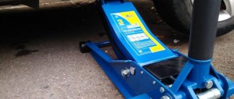
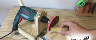
Spotter – straightening tool
A spotter is a welding machine for spot welding. This tool for straightening a car without painting makes it possible to repair parts that cannot be reached from the outside. Spotter straightening has the following advantages:
- No need to completely disassemble the car.
- High-quality result upon completion of work.
- Efficiency of execution.
- Possibility of repairing any mechanical damage to the body.
A spotter is a car straightening tool that copes with eliminating defects in doors, fenders, hood, sills and other body parts. It saves time and money on car repairs.
Preparation
Manufacturing a semi-automatic welding machine at home begins with planning the work. There are two options for making MIG welding from an inverter:
- Completely make a semi-automatic welding machine with your own hands.
- Only remake the inverter - buy a ready-made feeding mechanism.
In the first case, the cost of parts for the feeding device will be about 1000 rubles, excluding labor, of course. If a factory semi-automatic machine includes everything in one case, then a homemade one will consist of two parts:
- Welding inverter.
- Box with feeding mechanism and wire reel.
First, you need to decide on the body for the second part of the semi-automatic device. It is desirable that it be light and roomy. The feeding mechanism must be kept clean, otherwise the wire will feed jerkily; in addition, the reels must be changed periodically and the mechanism adjusted. Therefore, the drawer should be easy to close and open.
The ideal option is to use the old system unit:
- neat appearance - it doesn’t really matter, but it’s much nicer when the insides of the homemade product don’t stick out and the semi-automatic machine made from an MMA inverter looks good;
- light, closes;
- the body is thin - it’s easy to make the necessary cutouts;
- The gas valve and wire feed drive operate on 12 Volts. Therefore, a power supply from a computer will do, and it is already built into the case.
Now you need to estimate the size and location of future parts in the body. You can cut out approximate layouts from cardboard and check their relative position. After this, you can begin work.
The best option for electrode wire is a 5 kg coil. Its outer diameter is 200 mm, inner diameter is 50 mm. For the axis of rotation, you can use a PVC sewer pipe. Its outer diameter is 50 mm.
Determination of direct and alternating current
For direct current, no special circuits are required - there is a milliammeter, a powerful shunt with a resistance of hundredths and thousandths of an Ohm. They are connected in parallel with each other - and the entire installation is placed in an open circuit. For alternating current, a method with a current transformer connected according to the above-described circuit is required. To prevent the needle from oscillating around zero on the scale with a frequency of 50 hertz or more, a diode rectifier is used. This is one diode or diode bridge. The voltage rating of the diode must be high enough. This way you will avoid electrical breakdown and subsequent failure of the device.
Setting up an inverter used for semi-automatic welding
If you decide to make a semi-automatic welding machine with your own hands using an inverter, you must first turn off the power to this equipment. To prevent such a device from overheating, its rectifiers (input and output) and power switches should be placed on radiators.
Power diodes on additional radiators
In addition, in the part of the inverter housing where the radiator is located, which heats up more, it is best to mount a temperature sensor, which will be responsible for turning off the device if it overheats.
After all of the above procedures have been completed, you can connect the power part of the device to its control unit and connect it to the electrical network. When the network connection indicator lights up, an oscilloscope should be connected to the inverter outputs. Using this device, you need to find electrical pulses with a frequency of 40–50 kHz. The time between the formation of such pulses should be 1.5 μs, which is regulated by changing the voltage value supplied to the device input.
Oscillogram of welding voltage and current: on the left with reverse polarity, on the right with direct polarity
It is also necessary to check that the pulses reflected on the oscilloscope screen are rectangular in shape, and their front is no more than 500 ns. If all the checked parameters correspond to the required values, then you can connect the inverter to the electrical network. The current coming from the output of the semi-automatic device must have a force of at least 120 A. If the current value is less, this may mean that voltage is supplied to the equipment wires, the value of which does not exceed 100 V. If such a situation occurs, you must do the following: test the equipment by changing the current (in this case, it is necessary to constantly monitor the voltage on the capacitor). In addition, the temperature inside the device should be constantly monitored.
After the semi-automatic machine has been tested, it is necessary to test it under load. To make such a check, a rheostat is connected to the welding wires, the resistance of which is at least 0.5 Ohm. Such a rheostat must withstand a current of 60 A. The strength of the current that in such a situation flows to the welding torch is controlled using an ammeter. If the current strength when using a load rheostat does not meet the required parameters, then the resistance value of this device is selected empirically.
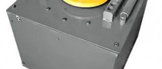
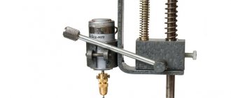
Ammeter for a homemade power supply.
In order to make a shunt, it is necessary to calculate its resistance. Go to the “Site Map” page, select the “Programs” category, go to the “Programs” note and download the “Program for working with wire”. Yes, there is a program. Now we take the measuring head, it is better if it has a current of full deflection of the needle of 50 or 100 microamps. These parameters are called the sensitivity of the measuring head. Let's make a calculation for a head with a current of 50 microamps. Let's set the measured current, let's say 10A.
1) We measure the resistance of the device (head), for mine it is 1454 Ohms. 2) We substitute all available data into formula 1: Device current - Idevice = 0.00005A; The measured current is Imeasured = 10A. Device resistance Rdevice = 1454 Ohms. 3) The shunt resistance was determined Rsh=0.00727 Ohm.
Open the program. Press the second button at the top to determine the length of the shunt. On the right, from the drop-down list, select the material for the shunt. For such ammeters, I always use light tinned tin from condensed milk cans as a material. And so, we choose steel.
Its resistivity is approximately 10 times greater than that of copper, so the geometric dimensions of the shunt will be smaller. We measure the thickness of the tin with a micrometer; mine is 0.2 mm. We choose the width of the strip of tin, nine millimeters for a current of ten amperes, I think, is enough, especially since the flat conductor has a large cooling area.
If it gets very hot, then the width can be increased and the shunt can be recalculated. We determine the cross-sectional area of our shunt S=0.2×9=1.8 square mm. Select the input value - “cross-sectional area”. Enter this value in the appropriate window. Enter the value of the required shunt resistance. Click on “Result” and get the length of the conductor equal to 74 millimeters. Take jar 1 (Photo 1) and cut out the corresponding strip from its tin. In the photo I showed what shapes the shunt can be given. Number 4 is a shunt for printed wiring; the ends of the strip are soldered to the printed pads. In general, I always slightly increase the length of such shunts, which leads to an increase in their resistance and, as a consequence, an increase in the voltage drop across a given shunt at the same current. But it becomes possible to accurately adjust the ammeter readings using an additional resistor connected in series with the measuring head. See photo2.
Of course, you can also use a copper winding wire as a shunt resistor, but then the shunt will be very long. Let's try it though. We enter new data in the appropriate windows. Let's look at the next screenshot_2. We get a shunt in the form of a wire 51 cm long. Do not wind the wire into a coil and concentrate the heat in one place. Just thread this piece of wire through
Remodeling methods
To begin with, let's consider possible options for converting an inverter into a semi-automatic welding machine.
To create a semi-automatic device, you will definitely need a so-called head unit. This is, in fact, a welding machine, which will form the operating parameters for the occurrence of an arc discharge. Not every inverter model is suitable as such a head unit.
It is necessary to choose a sufficiently powerful welding machine. Its current-voltage characteristics can be changed using a pulse-width modulation controller. However, firstly, not every home craftsman has such a device. Secondly, the measurement process is very long and labor-intensive. Finally, only a person with a sufficiently high level of knowledge in electrical engineering can carry out all the research.
Since the option with a PWM controller will not be available to the average welder, it is recommended to take a simpler route. Firstly, the selected donor device must normally perform all necessary operations. Secondly, to create a homemade semi-automatic you will need a choke. This part, intended for fluorescent lamps, can be purchased at any spare parts store. The inductor output voltage is used as a feedback input. How exactly to make a connection diagram and carry out the necessary installation operations is shown in the video below.
This option for creating a homemade semi-automatic machine is suitable only for happy owners of high-quality equipment. Namely, inverters capable of operating in a strictly specified current-voltage characteristic mode. Welders of this class are expensive, but they are most suitable for solving the task.
To make your own semi-automatic device, you will need:
- buy a wire feeder, complete with all the necessary wires and switching connectors;
- connect the feed mechanics to the inverter welding machine;
- select the current-voltage characteristic to work with a specific type of wire.
Wire feeder from Aliexpress
In essence, the feed mechanism acts as an attachment that expands the capabilities of the welding inverter. However, such a scheme has increased reliability and does not require special knowledge from the user. In addition, the resulting semi-automatic machine shows the maximum level of flexibility and unpretentiousness: it can be quickly configured to work with a specific material and wire.
This method will require considerable preparation from the user. Firstly, he will need to find a non-average inverter welding machine of suitable power. It is necessary to select the simplest possible donor of a certain class. The ideal device would be one that:
- there is a shunt at the output;
- a current transformer is used in the primary conversion block;
- ZX-7 layout.
It is recommended to choose devices without additional control options and functionality to make the life of the welder easier. The inverter should not have any hot starts, simple ignition, or arc forced.
To create your own homemade semiautomatic device, you will need to accurately set the current-voltage parameters of the selected inverter. You will also need to adjust the current increase. The order and list of required work is not universal. It differs for different inverter models.
Volt-ampere characteristics of the welding inverter
Connecting the device
Figure 3 shows a diagram of connecting meters in a laboratory source.
Rice. 3. Connection diagram of meters in a laboratory source.
Fig.4. Homemade automobile voltmeter on microcircuits.
Inverter conversion process
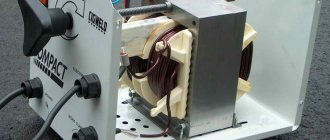
In a finished inverter, you first need to remake the transformer included in it. It is covered with an additional layer consisting of copper strip and thermal paper.
Ordinary copper wire cannot be used for a welding transformer. When welding, it overheats greatly and can stop the operation of the entire semi-automatic welding machine.
The secondary winding of the transformer will also require intervention. It is covered in three layers of tin, insulated with fluoroplastic tape. The ends of the applied winding are soldered. As a result of manipulation, the conductivity increases significantly.
An important element is a fan that will cool the device, protecting it from overheating.
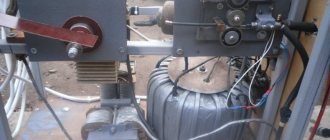
An inverter for manual welding can easily be converted into a power source for a semi-automatic machine. A functioning device does not need to be disassembled, but all additional equipment is placed in a separate housing. It houses a freely rotating spool of welding wire and a pulling mechanism. The side panel displays a wire speed regulator and a socket for connecting a hose.
An old computer system case will do just fine. It turns out compact and neat.
The current parameters can be adjusted on the inverter, then the “positive” terminal is connected to the workpiece from it.
The “negative” contact is removed from the inverter and goes into the new housing. Here it is connected to the sleeve terminal. It is important that the welding wire is connected to this potential.
The gas hose running from the cylinder to the burner is also attached to the housing. If you use the valve from a car windshield wiper, the gas supply will be adjusted.
The above arrangement is simple to implement, and the inverter can be simultaneously used for manual arc welding and as a power source for a home-made semi-automatic machine.
Step-by-step instruction
So
,
step one
- an SMD resistor with a resistance of 130 kOhm is removed from the circuit, standing at the input of the positive power wire, between the diode and the trimming resistor 20 kOhm.
Second
. On the freed contact, on the side of the trimmer, a wire of the desired length is soldered (for testing, conveniently 150 mm and preferably red)
Third
. A second wire (for example, blue) is soldered to the track connecting the 12 kOhm resistor and the capacitor from the “ground” side.
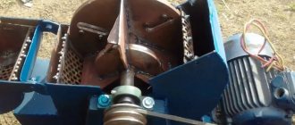
Creating a wire feeder
This block is needed to uniformly introduce consumables into the weld pool. The wire is selected taking into account the type of metals being connected and the result of the work. The feed mechanism must adapt to any type and size of consumables. The finished device is purchased at an electrical goods store.
It is allowed to make a unit with your own hands from the following improvised means:
- motor from car wipers;
- pressure shaft with spring;
- 3 bearings;
- metal plates 1 cm wide.
All parts are installed on a 5 mm thick textolite stand. The wire is inserted between the shaft and the bearing. The point where the filler material is discharged is compared with the fastening of the end of the hose used for gas inlet.
The wire is wound onto the reel evenly, the strength of the welded joints depends on this. The coil is placed on a support and secured. During operation, the wire unwinds and enters the seam. This mechanism facilitates and speeds up the welding process.
Lighting and ventilation
In garages, parallel circuits of lighting fixtures are more often used. One lamp allows you to use a specific area, several devices are turned on during a major renovation or a visit to the cellar. Minimum energy consumption is ensured by LED lamps. Daylighting devices have a great resource.
Cars use toxic, harmful fuels and lubricants, so do-it-yourself garage ventilation devices that allow you to create air exchange are becoming relevant. The influx is organized from below:
- garage - vents in the masonry, protected by bars;
- cellar - pipe from the garage or from the street.
Ventilation of the garage and cellar underneath
The hood is mounted under the ceiling of the cellar, the roof of the garage, or has the form of vents in the main walls at the highest points.
Related article:
Assembly of the unit
The assembly instructions will help you make a quality semi-automatic welding machine. The work is carried out in the following sequence:
- Connect the inverter to power and control devices.
- Thread the wire into the feed mechanism and check for smooth movement.
- Set the required wire feed speed.
- Connect the burner to a hose, which is connected to the feeder.
- Connect a gas cylinder with a reducer and a pressure gauge to the burner.
- Turn on the inverter and feeder.
- Check the flow of gas and wire. After gas supply, the delay in wire movement should be 1–2 s. It enters a ready-made protective environment, otherwise it will stick.
When preparing a home-made semi-automatic machine for the first start-up, you need to take care of cooling the assembled semi-automatic welding machine so that it does not overheat. For this purpose, input and output rectifiers and power switches are mounted on radiators. On the inverter body where the radiator is located, that is, in the most heated zone, it is recommended to install a temperature sensor that will de-energize the device if it overheats.
After this, connect the power part to the control unit, and then turn on the semi-automatic device to the power supply. When the mains lights come on, the inverter needs to be tested. At the output of the device, a current is measured, which should not exceed 120 A. If its value is less, this means that a voltage below 100 V is supplied to the equipment through the wires. In this case, the current is changed and the voltage is controlled, achieving the desired parameters. In this case, the inverter should not overheat.
Under load, the semi-automatic device is checked as follows. The welding wires are connected to a rheostat designed for a current of 60 A and a resistance of at least 0.5 Ohm. The current supplied to the burner is controlled with an ammeter. If the current strength differs from the norm, change the resistance value.
After turning on the assembled semi-automatic device, the indicator should show a current strength of 120 A. This figure confirms the correctness of the work. If eights are displayed, then the reason is insufficient voltage in the supply wires. Welding inverters operate in the operating current adjustment range of 20–160 A.
Schematic diagram of a voltmeter
Now closer to the diagram. Figure 1 shows a circuit of a voltmeter that measures voltage from 0 to 100V (0.99.9V). The measured voltage is supplied to pins 11-10 (input) of microcircuit D1 through a divider on resistors R1-R3.
The SZ capacitor eliminates the influence of interference on the measurement result. Resistor R4 is used to set the instrument readings to zero; in the absence of input voltage, and resistor R5 is used to set the measurement limit so that the measurement result corresponds to the real one, that is, we can say that they calibrate the device.
Rice. 1. Schematic diagram of a digital voltmeter up to 100V on SA3162, KR514ID2 microcircuits.
Now about the outputs of the microcircuit. The logical part of the CA3162E is built using TTL logic, and the outputs are also with open collectors. At the outputs “1-2-4-8” a binary decimal code is generated, which changes periodically, providing sequential transmission of data on three digits of the measurement result.
If a TTL decoder is used, such as KR514ID2, then its inputs are directly connected to these inputs of D1. If a CMOS or MOS logic decoder is used, then its inputs will need to be pulled to positive using resistors. This will need to be done, for example, if the K176ID2 or CD4056 decoder is used instead of KR514ID2.
The outputs of the decoder D2 are connected through current-limiting resistors R7-R13 to the segment terminals of the LED indicators H1-NC. The same segment pins of all three indicators are connected together. To poll the indicators, transistor switches VT1-VT3 are used, to the bases of which commands are sent from the outputs H1-NC of the D1 chip.
Read also: Shaped cutter for lathe
These conclusions are also made according to an open collector circuit. Active zero, so transistors of the pnp structure are used.
DIY making
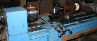
The easiest way is to make a homemade semi-automatic machine from an inverter based on a powerful power unit.
You can make an inverter yourself or use it from existing equipment. For semi-automatic devices, inverters with a capacity of at least 150 amperes should be used. There are schemes for modifying equipment that allow you to set the power that will be enough to carry out semi-automatic welding. A device of this type will be difficult to implement, so the use of low-power power units can only be recommended to experienced radio amateurs who can produce truly complex equipment.
You can produce high-quality equipment if you have on hand the starting circuit for a semi-automatic welding inverter. The characteristics of such a unit include the following:
- Primary current - 8-12 A.
- Supply voltage - 220 or 380 volts.
- Open circuit voltage is 36-42 Volts.
- Welding current - 40-120 amperes.
- Voltage adjustment in increments of plus or minus 20%.
These are the optimal parameters for a household semi-automatic welding machine that can cope with metals of different refractoriness indices. Subsequently, using additional drawings for increasing the power of the inverter, you can change the basic characteristics, which allows you to use such equipment for domestic and industrial purposes .
Scale graduation
The scale calibration of a galvanometer (not a ready-made ammeter) is conditional - it depends on the following parameters:
For example, to calibrate a device at 15 volts (car generator voltage) to 15 amperes, the shunt must have a resistance of 1 ohm. If the charging current is high - 75 A, then a powerful shunt element of 0.2 Ohm is installed. The correction for the resistance of the galvanometer winding in this case will be very small - it itself is at least hundreds of times higher than that of a shunt connection, and the error of such an ammeter will be 0.2% or less. An accurate calculation can be made using the above formula, taking into account the resistance of the galvanometer winding. If we are talking about high currents, it is no less logical to include a fuse or automatic fuse in the open circuit in series with the ammeter - in case the device goes “off scale”.
To learn how to properly connect an ammeter, see the following video.
Source
Rework algorithm
The vast majority of components are used without significant modifications. Re-equipment will be required for the filler material feeder, since the feed rate of the filler through the flexible hose must match the melting rate of the filler metal. It is necessary to take into account the adjustment option in the mechanism, because the speed varies based on the type of metal being welded, the type and cross-section of the filler material.
In a working inverter, first of all, the transformer device included in its structure should be rearranged. It is covered with an additional layer consisting of a copper strip and paper with a heat-sensitive coating.
Do not use ordinary copper wire for the transformer device. During the welding cycle, it heats up too much and can stall the operation of the entire semi-automatic welding unit.
The secondary winding of the transformer device also requires improvement. It is covered in 3 layers of thin sheet steel, insulated with fluoroplastic tape. The ends of the wound winding are connected by soldering. After performing these steps, electrical conductivity increases significantly.
An important component is the fan, which will cool the unit, protecting it from excessive heating.
A current converter for manual electric welding very easily becomes a power source for a semi-automatic unit. The working device can not be disassembled, and all auxiliary equipment can be located in another building. It contains a reel with filler material, which rotates freely on the drum, and a feeding device. On the side of the casing there is a speed converter for the filler material and a connector for connecting the guide hose.
A used PC system case will easily do. It will turn out neat and concise.
The parameters of the electric current can be adjusted on the inverter, therefore, the “positive” terminal is connected to the part from it.
“Minus” is removed from the inverter and inserted into a new supporting shell. Here it is connected to the terminal of the supply hose. The main thing is that the filler material is connected to this potential.
The hose for supplying the protective gas mixture, which runs from the cylinder to the burner gun, is also fixed in the housing. If you use the valve from the car's windshield wipers, the gas mixture supply setting will appear.
The presented assembly is simple to implement, and the inverter can be used in parallel for manual electric arc welding and as a power source for a welding unit made at home, operating in a semi-automatic mode.
How to monitor the correct operation of equipment
In order for the semi-automatic welding machine that you assembled with your own hands to serve you for a long time, it is better to constantly monitor the temperature conditions of the inverter. To carry out such control, you need to press two buttons simultaneously, after which the temperature of the hottest inverter radiator will be displayed on the indicator. The normal operating temperature is considered to be one whose value does not exceed 75 degrees Celsius.
If this value is exceeded, then, in addition to the information displayed on the indicator, the inverter will begin to emit an intermittent sound signal, which should be noted immediately. In this case (as well as if the temperature sensor breaks or shorts), the electronic circuit of the device will automatically reduce the operating current to 20A, and a sound signal will be emitted until the equipment returns to normal. In addition, a malfunction of self-made equipment may be indicated by an error code (Err) displayed on the inverter indicator.
Setting the welding mode on the Resanta inverter
Features of the device
How to make an electronic LED voltmeter-thermometer on a microcontroller for a car from a calculator with your own hands? How to connect a voltmeter with an ammeter in a car to the cigarette lighter? First, let's look at the main features of automotive voltmeters.
Description
The main purpose of the device is to measure the voltage parameter in the automotive network. Analogue and tube devices are equipped with a scale with a pointer indicator, but it is better to install a digital gadget in the car. In such devices, all parameters are displayed. Switch devices are gradually fading into the background; today they are obsolete (video published by the China channel in SHOPe).
Varieties
Voltmeters can be either standard or combined:
- The key feature of standard voltmeters is their fairly small dimensions, which makes it possible to install the device absolutely anywhere in the car’s interior. In practice, such devices are most often connected to the cigarette lighter. With this connection, the voltmeter will be able to record the voltage in the network both when the power unit is running and when it is switched off. In the first case, the operating parameter should be 13.5-14.5 volts, in the second - about 12.5 V.
- Combined devices. Such devices can also be equipped with tachometers, ammeters and even thermometers. Combined voltmeters are considered more functional devices, so they are more in demand on the market.
How to use a welding inverter
After starting the semi-automatic device that you assembled with your own hands, the inverter indicator should display a current value of 120 A. If everything is done correctly, then this will happen. However, the inverter indicator may display a figure of eight. The reason for this is most often insufficient voltage in the welding wires. It is better to immediately find the cause of such a malfunction and promptly eliminate it.
If everything is done correctly, the indicator will correctly show the strength of the welding current, which is adjusted using special buttons. The operating current adjustment interval provided by welding inverters is in the range of 20–160 A.
Approximate modes of semi-automatic welding of butt seams
Details
Perhaps the most difficult to obtain are CA3162E microcircuits. Of the analogues, I know only NTE2054. There may be other analogues that I am not aware of.
The rest is much easier. As already said, the output circuit can be made using any decoder and corresponding indicators. For example, if the indicators have a common cathode, then you need to replace KR514ID2 with KR514ID1 (the pinout is the same), and drag the transistors VT1-VTZ down, connecting their collectors to the power supply negative, and the emitters to the common cathodes of the indicators. You can use CMOS logic decoders by connecting their inputs to the power supply positive using resistors.
Semi-automatic Sanych
Craftsman Sanych offers a semi-automatic welding circuit that is simple and accessible even for beginners.
The proposed design is characterized by a soft hiss of the arc, while crackling and clicking noises are observed in magazine devices. The hard mode is obtained there due to the output characteristics of the transformer 18–25 V.
The transformer consists of four cores from the TS-270 connected together. The result is almost 2 thousand watts. This power is sufficient with reserve. The primary winding (180+25+25+25+25) is made of wire with a cross-section of 1.2 mm. For the secondary (35+35 turns) an 8 mm² bus is used. The number of turns of the secondary winding is determined last, so it is better to make a couple of turns in each arm with a reserve. The excess can be rewinded.
Welding device diagram:
The rectifier circuit is full-wave. To switch the current there is a paired bib. Two diodes in a small radiator. It is recommended to take capacitors of at least 30 thousand microfarads.
The power part is switched on by any of the powerful contactors, for example models KM-50D-V or KP-50D-V. With the passport data 27 V and at 15 V they work stably. The contactor allows you to obtain high switching power at the lowest current of 300–400 mA.
The TS-40 supply transformer is rewound to give an output voltage of 15 V.
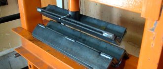
For the broaching mechanism, a roller with a diameter of 25–28 mm is used. On the guide you need to make a groove 0.5 mm wide by 1 mm deep. It is secured to the motor shaft with a nut. The output of the regulator is 6 V, and this is enough for optimal supply. If the lower limit is exceeded, a stabilizer with a lower operating voltage is selected.
The handle holder is machined from textolite sheets 10 mm thick. The seats are made with a drill using drills and an end mill.
The protection hose is held in place on both sides by spacer sleeves. For reliability, there are grooves on the mating parts.
The body will require a 1 m thick sheet of iron with a double flange along the edge. The cooling fan is installed on the rear wall, just opposite the power transformer. The semi-automatic welding machine moves on wheels.
The assembled semiautomatic device is connected to the network for testing. It should not overheat and clearly respond to current adjustment. The transformer insulation is also checked. In case of problems, additional coating is applied. You also need to check the feeding mechanism: how evenly and quickly it feeds the wire. The device has worked faithfully for more than 10 years.
A well-made semi-automatic machine will serve its owner for a long time and reliably, and if you have experience in making a semi-automatic welding machine with your own hands, be sure to share it in the comments to this article.
A semi-automatic welding device for household needs can be purchased ready-to-use or completely assembled with your own hands. A homemade semi-automatic machine will cost the performer much less, but its assembly will require certain skills in working with electrical equipment. The appearance of such a welded device is shown in the figure below.
We recommend that everyone who wants to make a semi-automatic machine from an inverter with their own hands first familiarize themselves with the structure of this unit and the operating features of the modules included in it.