Any welder knows about the advantages of semi-automatic welding over manual electric welding. Due to their widespread use and low cost, MMA inverters are in the arsenal of many craftsmen. But with MIG welding it’s a different matter – these devices are more expensive. But there is a way out - you can make a semi-automatic device from an inverter with your own hands. If you delve into this issue, the matter turns out to be not so complicated.
Semi-automatic device
The structure of a semi-automatic machine is the first thing you need to study if you want to assemble your own machine.
A standard semi-automatic machine consists of two parts (or two blocks): power and feed. The feed part is simply a feed device for semi-automatic welding. But, let's take a closer look at the semi-automatic device.
The power part, also known as the power unit, is essentially an inverter. The inverter acts as a current source. Everything is simple here. But the feeding part is a separate, plug-in feeding mechanism. The feed mechanism is used to feed the wire. The wire is sold in reels and the reel is inserted directly into the feeder. Its end exits through the burner nozzle.
Of course, you don't have to use a feed mechanism to perform semi-automatic welding. The wire can also be fed manually. But this is extremely inconvenient, and in this case the whole essence of semi-automatic technology is lost.
That's all the components. This, of course, is not enough to make a semi-automatic welding machine on your own. You will also have to buy additional parts, but they depend on the type of inverter you have and the method by which you will convert it into a semi-automatic machine. Don’t forget about the components (burner, hose, correctly selected nozzle, etc.).
Feeder design
The process of assembling a semi-automatic welding machine with your own hands can take place either using a factory feeding device or its home-made version. In order to make it yourself, you need to understand what the factory product consists of, namely:
- on the front panel there is a Euro connector for connecting a welding sleeve;
- on the back of the case there is a toggle switch for turning on the power supply and connectors for connecting to the inverter and gas supply system;
- inside the case there is a power supply unit for the feeding device;
- feed unit with a fixed, freely rotating spool of wire;
- Next there is a clamping, adjustable feeding device connected through a gearbox to the electric motor shaft;
- circuit for adjusting the speed of the electric motor, ensuring the forward movement of the welding wire at a given speed;
- a solenoid that provides or shuts off the gas supply to the burner through the valve;
- gas supply tubes to the solenoid and Euro connector;
- power cable supplying welding current to the wire feed unit;
- a scheme for coordinating gas supply and wire movement with a delay of 1-2 seconds, preventing burnout or sticking of the wire when working in an aggressive oxygen environment;
- cables connecting the inverter and the feeder.
It is important that the feed system be mounted on electrically insulating material, since the welding wire is energized and acts as an electrode, and electrical contact with the equipment frame must be prevented.
It is necessary to ensure effective adjustable pressure on the feed roller, since the wire has a different cross-section, depending on the thickness of the workpieces being welded. It is important to ensure the ratio of all nodes involved in ensuring the translational movement of the wire in order to avoid kinks that impede smooth feeding at the required speed. The material of the gas supply hose must be heat-resistant, and the connections must be provided with reliable clamps. It won’t be difficult to choose a power supply with suitable parameters that will ensure the operation of the electric motor and electronic circuits of the feeder.
Principle of operation
The operating principle of the semi-automatic device is simple. It will be clear even to a beginner, so study this information carefully. It will be useful for assembling a homemade device.
So, it all starts with feeding the torch into the welding zone. The torch combines two devices: from its nozzle it supplies protective gas and wire simultaneously. The welder regulates the amount of gas manually, but the wire is fed in a semi-automatic mode (hence the name “semi-automatic”). That is why the welder always has only one hand occupied during the process. The one holding the burner.
As we have already said, gas is supplied to the welding zone simultaneously with the wire. An electric discharge is formed in the mixture of gases between the end of the wire and the metal surface, due to which the workpiece and the wire itself melt. Molten metal is mixed with molten wire. Next, you can form the seam.
In this case, wire is necessary and without it welding is simply impossible. Gas is also needed; it protects the weld pool from oxygen coming from outside. But if you do not have the opportunity to use gas, you can take a special cored wire and cook only with it.
In what cases is a semi-automatic welding machine used?
Practice shows that it is better to use a semi-automatic machine in cases where it is necessary to obtain precise and accurate connections of parts made of steel. With the help of such equipment, which, if desired, can be made by hand, welded joints of thin metal are made, which is very important when repairing the body of a vehicle.
Learning how to operate such a device is also not difficult: lessons taken from qualified specialists or a training video will help you with this.
Modernization of semi-automatic welding machine
A semi-automatic welding machine is a functional device that can be purchased ready-made or made from an inverter with your own hands.
It should be noted that making a semi-automatic device from an inverter device is not an easy task, but it can be solved if desired.
Those who set such a goal should thoroughly study the operating principle of a semi-automatic device, watch thematic photos and videos, and prepare all the necessary equipment and components.
Scheme of semi-automatic welding in a shielding gas environment
The main differences between a welding inverter and a semi-automatic machine
Often, the master is faced with the question of choosing between an inverter or a semi-automatic welding machine, the difference between which lies in the quality of the seam and the types of metals being welded. If a conventional inverter allows welding in AC/DC mode, with piece electrodes of different thicknesses, then semi-automatic welding machines connect parts with welding wire. It is fed into the melting zone at a controlled speed and has different thicknesses, and to ensure the best result, the process takes place in an inert or active gas (MIG/MAG) environment. Semi-automatic machines allow you to weld all kinds of metals of various thicknesses, while the size of the electrode does not change and the working area is always at the same distance from the person. The semi-automatic welding machine contains an inverter, but also contains an adjustable wire feed unit and a special hose with a torch and cylinder. This equipment can weld aluminum alloys, carbon and stainless steel, cast iron and titanium, and with special wire - brass and galvanized metal. When assembling a semi-automatic machine from an inverter with your own hands, you will need the following factory or home-made components:
- welding machine with AC/DC modes, outputting adjustable currents from 10 to 200A, with variable pulse voltage;
- a torch with the ability to supply welding wire and the corresponding gas to the place of welding work;
- a hose reinforced with a spring to ensure uninterrupted supply of wire and gas;
- gas cylinder with reducer and pressure gauge;
- reverse welding cable with clamp;
- Control block;
- reliable, adjustable unit for feeding welding wire of various thicknesses.
These elements can be purchased factory-made, and some of them can be made by hand. The inverter, burner and gas cylinder must be purchased from the manufacturer, since the technical requirements for these components require a quality certificate.
Of course, your own semi-automatic machine will cost much less, but it is important that home-made elements meet safety requirements when performing electric welding work.
Construction of a torch and hose for a semi-automatic welding machine
Using a semi-automatic welding machine, we can increase the speed of work by more than two and a half or three times, since there is no need for multiple passes of the seam, its cleaning and replacement of piece electrodes. To increase productivity, it is necessary to ensure an uninterrupted supply of inert gas, voltage and wire to the weld pool. For this purpose, use a device consisting of the following components:
- a cylinder with a reducer, adjusted to a flow rate of 6-10 liters per minute and equipped with a gas supply hose;
- Euro-sleeve, hose-cable 3 m long, through which current, wire and gas are supplied, as well as a control signal;
- a torch with a tip, a power button and a nozzle for different wire diameters, equipped with a nozzle for inert or active gas.
Creating a Euro-sleeve yourself is quite difficult; you need to take into account that the diameter of the wire used ranges from 0.8 to 1.6 mm, and it must pass through the welding hose without any hindrance. For this purpose, the channel is equipped with a spring, using a Teflon coating; in addition, a gas supply passes through the same hose. The control signal from the burner button also passes through the cable, and at the end there is usually a multi-pin Euro connector, through which all components are turned on and supplied.
The complex design of the torch and its operation at high temperatures implies the presence of refractory nozzles with holes for different diameters of welding wire. Gas is supplied through the torch, as well as the wire feeding mechanism to the weld pool is turned on. It consists of the following elements:
- handle with control button;
- burner;
- gas nozzle;
- calibrated current-carrying tip.
It is important to ensure the reliability of electrical contacts and tight connections of gas hoses.
What is needed to convert an inverter into a semi-automatic machine?
To convert an inverter into a functional semi-automatic welding machine, you must find the following equipment and additional components:
- an inverter machine capable of generating a welding current of 150 A;
- a mechanism that will be responsible for feeding the welding wire;
- the main working element is the burner;
- a hose through which the welding wire will be fed;
- hose for supplying shielding gas to the welding area;
- a coil of welding wire (such a coil will need to undergo some modifications);
- an electronic unit that controls the operation of your homemade semi-automatic machine.
Electrical circuit of a homemade semi-automatic machine
Special attention should be devoted to redesigning the feeding device, due to which welding wire is supplied to the welding zone, moving along a flexible hose. In order for the weld to be high-quality, reliable and accurate, the wire feed speed through the flexible hose must correspond to the speed of its melting.
Since when welding using a semi-automatic machine, wire of different materials and different diameters can be used, its feed speed must be adjusted. It is precisely this function – regulation of the welding wire feed speed – that the feed mechanism of a semi-automatic device should perform.
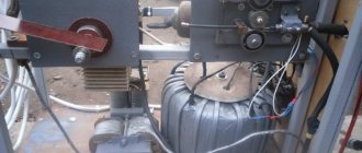
Appearance of a homemade semi-automatic welder
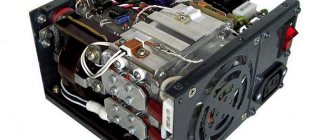
Internal layout
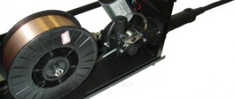
Wire spool
Wire feeder (type 1)
Wire feeder (type 2)
Attaching the welding sleeve to the feed mechanism
Homemade burner design
The most common wire diameters used in semi-automatic welding are 0.8; 1; 1.2 and 1.6 mm. Before welding, the wire is wound onto special reels, which are attachments of semi-automatic devices, fixed to them using simple structural elements. During the welding process, the wire is fed automatically, which significantly reduces the time spent on such a technological operation, simplifies it and makes it more efficient.
The main element of the electronic circuit of the semi-automatic control unit is a microcontroller, which is responsible for regulating and stabilizing the welding current. The parameters of the operating current and the possibility of their regulation depend on this element of the electronic circuit of the semi-automatic welding machine.
Burner
A homemade semi-automatic machine must be equipped with a burner. You can do it yourself, but it’s better to buy a ready-made kit, which includes:
- Burner with a set of tips of different diameters.
- Supply hose.
- Euro connector.
A normal burner can be purchased for 2-3 thousand rubles. Moreover, the device is homemade, so you don’t have to chase expensive brands.
What to look for when choosing a kit:
- what welding current is the torch designed for;
- the length and rigidity of the hose - the main task of the hose is to ensure free flow of wire to the torch. If it is soft, any bend will slow down the movement;
- springs near the connector and burner - they prevent the hose from breaking.
How to properly set up a semi-automatic welding machine. Semi-automatic welding setup table
Many home workshops are equipped as well as specialized professional services. Including equipment for welding work. But not all the capabilities of the devices are used to their full extent.
The reason is that not every amateur will be able to independently set up welding to work with aluminum, stainless steel or other metals. Instructions are sometimes not enough. The missing link may be the experience of production workers.
Settings are influenced by external parameters
The thickness of the workpieces, the spatial position of the welded joint, the configuration of the joint, the need to strengthen the leg and other indicators require adjustments in the machine settings. Basic settings for semi-automatic welding:
- current strength – filler wire feed. The dependence is directly proportional: increasing the wire feed speed requires higher values in the current settings;
- arc voltage. The adjustment values affect the amount of current;
- shielding gas consumption depends on the basic welding parameters.
Primary values can be set using the tuning table. Next, test welding of a certain number of elements is performed. Based on its results, the settings are adjusted.
After purchasing a semi-automatic device, it takes time to get used to the features of its operation. Over time, even the sound of an electric arc will become informative for the user. In the meantime, you need to get used to the changes:
- The equipment of semi-automatic devices with identical performance indicators can differ greatly. Differences in settings are not uncommon even among models from the same manufacturer;
- due to voltage fluctuations, semi-automatic welding settings are lost;
- changing the brand and composition of the wire;
- change in gas composition;
- Even minor repairs, and even more so the replacement of components, lead to changes in the operation of the equipment.
Gas protection
The gas flow is also a reference value and does not directly affect the settings of the welding unit. Control of gas consumption is greatly simplified, provided that the reducer has two scales. More precisely, the flow volume is taken into account by the rotameter, which is quite often installed on industrial welding lines.
The rotametric indicator of gas flow provides data on the supply of inert gas to the welding process zone in constant quantities. The static pressure will be reduced when the burner fires and creates a cloud of shielding gas. The starting range for the rotameter is 6 to 10 liters per minute. In cases where a pressure gauge is installed - about 1-2 atmospheres.
The gas consumption rate is selected depending on the presence of pores in the weld area. The gas flow increases in volume until the pores disappear. The use of gas in windy or drafty rooms is not justified. Here it is better to resort to flux-coated wire.
Selection of gas mixture
The choice of protective gas mixture is influenced by two factors - the properties of the materials being welded and the quality requirements:
- carbon dioxide ideally protects weld pools. It is an ideal option for ensuring deep penetration. But it is not suitable for fine work due to the rough appearance of the seam and high spattering;
- argon in combination with carbon dioxide in a 3:1 ratio is used for welding thin-sheet workpieces. A thin, high-quality seam is formed and a minimal amount of spatter is generated;
- for stainless steel, the optimal gas mixture is a composition of argon (98%) and carbon dioxide (2%);
- When welding aluminum, pure argon is used.
Voltage setting
Changes in voltage are determined by the energy costs of melting the metal and burning the arc. An increase in energy consumption causes an increase in the thickness of the consumable material and the penetration depth of the workpieces. Household semi-automatic devices are configured using a stepwise method.
There is a reference table for selecting voltage values on the inside of the casing cover. This is important information from the manufacturer, which allows you to select optimal power values for each model, taking into account specific operating conditions.
Wire feed speed
The value of the current depends on the speed at which the consumable material is supplied to the melt zone. The amount of wire feed is one of the main variable parameters. It is selected after the voltage has already been set, since the intensity of melting directly affects the feed rate.
The value varies depending on the grade and diameter of the material used and after each change in voltage values. There is equipment on the market with automatic parameter settings. However, it is one of the expensive semi-automatic machines.
To optimize semi-automatic welding settings, fine adjustments of values are required. If the filler wire is fed too quickly, sagging will form; Slow feed will cause seam breaks, sag or waviness. A good roller is impossible without precise balancing of three parameters: voltage, current and consumable feed speed.
Too high a feed appears immediately after starting work. With the arc ignited, the feed speed decreases, but the wire does not stop bending, sticking to the metal surface and does not have time to melt. In this case, active production of splashes is observed.
Insufficient supply manifests itself in the fact that the electrode burns out even before touching the metal. In this case, the tip from which the consumable material is supplied will become clogged.
Thus, we can conclude: the correct choice of feed speed mode and current value with previously set voltage settings is the first step to professional growth.
Table of the direct relationship between the adjustments and the result of the work:
Polarity
Changing polarity is one of the simplest adjustments. Under the cover of most semi-automatic machines there is a sign with information about which metal requires direct or reverse polarity.
A novice welder must firmly understand that with direct polarity, the torch is connected to the negative terminal.
With this switching scheme, the wire melts one and a half times faster, but the stability of the electric arc deteriorates.
With direct connection, workpieces are welded using flux-coated wire. Most of the thermal energy goes to protect the welded joint. The flux reacts completely and there is no free residue. The main costs of the method are an abundance of splashes and a decent amount of slag.
The copper-clad solid wire must be powered from the positive terminal. Preparation of workpieces to be welded consists of cleaning the surface and cutting. As the diameter of the wire increases, the conductivity also increases. Therefore, when working with large workpieces, it is advisable to increase the diameter of the consumable.
Wire release and ejection
The quality of the weld is affected by the length of the consumable material extending from the tip, as well as the size of the gap between the wire and the working surface. The discrepancy between the diameter of the wire and the size of its exit from the tip leads to excess spatter, metal burning, lack of fusion and warping.
Some designs of semi-automatic machines provide the ability to change the location of the burner tip relative to the nozzle. They are located at the same level, but the contact tube in relation to the nozzle can be extended or, conversely, recessed. The adjustment amplitude is 3.2 mm.
Short overhang is used to form welds on low alloy structural steel. As the distance increases in this case, the effectiveness of the protective gas cloud decreases. In order to increase the melting point, you can lengthen the flux wire slightly.
Release and overhang directly depend on the diameter of the filler wire:
Arc setting
Even relatively inexpensive models of semi-automatic welding are equipped with inductance control verniers. These settings change the temperature of the welding arc, the depth of metal penetration, and the convexity of the joint. You can work with parts that are sensitive to overheating; thin sheet materials no longer pose a serious problem for the welding machine.
The increase in inductance occurs due to compression of the current channel. As the index increases, the melting temperature and melt depth will also increase; the weld pool becomes more liquid. The bead of the finished seam will be flatter. With a small diameter of the filler wire, the arc becomes more stable, the melting coefficient and the depth of metal penetration increase; the amount of splashes is reduced.
Weld parameters depending on inductance:
Semi-automatic setup table
Before starting work, it will not be superfluous to clarify the basic settings of the semi-automatic machine. The table below is provided as a guide. All values in it are advisory in nature and express the relationship of all objective components of the process:
The influence of voltage on connection quality
A beautiful seam without pores, sufficiently convex, without undercuts, sagging and other defects can be obtained only if the tension is balanced with other adjustments. At low voltage, the weld seam is narrow with a shallow penetration depth. And vice versa - with high stress levels, the seam will turn out to be too wide and high; the crater of the bath will be deep.
Problems and errors
In the case of blind copying of average data on equipment settings, which are given in various reference books and tables, problems and mistakes cannot be ruled out. The fault here lies entirely with the welder. It is important to consider not only recommendations, but also the subtleties of performing each specific task. Attention to detail and a creative approach are the keys to successful completion of the job.
Experienced specialists immediately detect incorrect operation of the equipment. Here are some of the signs:
- Clicks and crackles indicate that the supply speed of the consumable is not high enough;
- if the solder begins to melt near the tip itself at a decent distance from the joint, then its feed speed is low;
- too much splashing: you need to increase the inductance and gas supply;
- the seam is replete with shades of green or brown and turns out to be porous - gas protection is not good enough;
- uncooked areas, as well as burned areas, indicate the need to adjust the voltage. It is possible that you need to turn the inductance regulator;
- a combination of lack of penetration, instability of the arc and an inhomogeneous seam - the contact of the mass has weakened or there is a lot of different debris in the welding environment (possibly due to the surface of the workpieces being poorly prepared for work);
- notches and uneven fullness of the bead; the speed of the torch along the seam is impaired;
- intermittent seam + excessive spatter – arc length is very long.
Preparation
Manufacturing a semi-automatic welding machine at home begins with planning the work. There are two options for making MIG welding from an inverter:
- Completely make a semi-automatic welding machine with your own hands.
- Only remake the inverter - buy a ready-made feeding mechanism.
In the first case, the cost of parts for the feeding device will be about 1000 rubles, excluding labor, of course. If a factory semi-automatic machine includes everything in one case, then a homemade one will consist of two parts:
- Welding inverter.
- Box with feeding mechanism and wire reel.
First, you need to decide on the body for the second part of the semi-automatic device. It is desirable that it be light and roomy. The feeding mechanism must be kept clean, otherwise the wire will feed jerkily; in addition, the reels must be changed periodically and the mechanism adjusted. Therefore, the drawer should be easy to close and open.
The ideal option is to use the old system unit:
- neat appearance - it doesn’t really matter, but it’s much nicer when the insides of the homemade product don’t stick out and the semi-automatic machine made from an MMA inverter looks good;
- light, closes;
- the body is thin - it’s easy to make the necessary cutouts;
- The gas valve and wire feed drive operate on 12 Volts. Therefore, a power supply from a computer will do, and it is already built into the case.
Now you need to estimate the size and location of future parts in the body. You can cut out approximate layouts from cardboard and check their relative position. After this, you can begin work.
The best option for electrode wire is a 5 kg coil. Its outer diameter is 200 mm, inner diameter is 50 mm. For the axis of rotation, you can use a PVC sewer pipe. Its outer diameter is 50 mm.
Pulling device
In a more complex case, the manufacture of a semi-automatic machine involves reworking the arc welding inverter and creating a broaching device from scrap materials. If you had to repair an inverter device, then you can safely implement the second option.
A system unit is ideal as a housing for a drawing device for an inverter-type semi-automatic device. It is quite easy to open, yet spacious and durable.
This will allow you to simply adjust the pressure of the rollers and install the spool of wire. The advantage of the system unit is that it is easy to make holes in the right places, and there is a built-in 12-volt power supply. It is needed to power the additive broach drive and the gas valve.
For the necessary fasteners, it is necessary to make mock-ups of the built-in components from scrap materials and try them on inside the box. After making sure that the selected layouts are correct, you can begin manufacturing the fasteners.
You can buy a reel for a semi-automatic machine ready-made or make it yourself. It is very simple to produce. The diameter of the cheeks should be 200 mm, and the cylinder on which the wire will be wound should have a diameter of 50 mm, so that a plastic pipe with the same rating can be used as an axis.
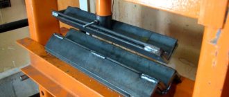
The feed mechanism will require two pressure rollers and one guide roller and a spring. An electric motor from the wipers can be used as a broaching motor. As a base on which the parts will be attached, you need to use a three-millimeter metal sheet.
Holes are drilled in the plate in the right places for attaching the rollers and the electric motor shaft of the future semi-automatic device. Since one roller is a pressure roller, the hole for it is drilled in an oblong shape.
A pressure spring will press on it from above, the force of which is adjusted through a screw. The roller and bearings are mounted on one side of the plate, and the motor on the other. A feed roller is mounted on the motor shaft.
The resulting device is installed inside the system unit so that the alignment of the rollers and the axis of the MIG torch connector are in the same plane. This will prevent the wire from creasing when pulling. To straighten the additive during unwinding, a tube is installed in front of the rollers.
Setting up an inverter used for semi-automatic welding
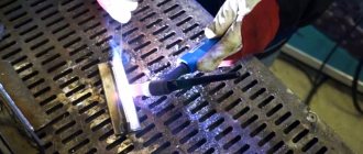
If you decide to make a semi-automatic welding machine with your own hands using an inverter, you must first turn off the power to this equipment. To prevent such a device from overheating, its rectifiers (input and output) and power switches should be placed on radiators.
Power diodes on additional radiators
In addition, in the part of the inverter housing where the radiator is located, which heats up more, it is best to mount a temperature sensor, which will be responsible for turning off the device if it overheats.
After all of the above procedures have been completed, you can connect the power part of the device to its control unit and connect it to the electrical network. When the network connection indicator lights up, an oscilloscope should be connected to the inverter outputs. Using this device, you need to find electrical pulses with a frequency of 40–50 kHz. The time between the formation of such pulses should be 1.5 μs, which is regulated by changing the voltage value supplied to the device input.
Oscillogram of welding voltage and current: on the left with reverse polarity, on the right with direct polarity
It is also necessary to check that the pulses reflected on the oscilloscope screen are rectangular in shape, and their front is no more than 500 ns. If all the checked parameters correspond to the required values, then you can connect the inverter to the electrical network. The current coming from the output of the semi-automatic device must have a force of at least 120 A. If the current value is less, this may mean that voltage is supplied to the equipment wires, the value of which does not exceed 100 V. If such a situation occurs, you must do the following: test the equipment by changing the current (in this case, it is necessary to constantly monitor the voltage on the capacitor). In addition, the temperature inside the device should be constantly monitored.
After the semi-automatic machine has been tested, it is necessary to test it under load. To make such a check, a rheostat is connected to the welding wires, the resistance of which is at least 0.5 Ohm. Such a rheostat must withstand a current of 60 A. The strength of the current that in such a situation flows to the welding torch is controlled using an ammeter. If the current strength when using a load rheostat does not meet the required parameters, then the resistance value of this device is selected empirically.
Remodeling methods
To begin with, let's consider possible options for converting an inverter into a semi-automatic welding machine.
To create a semi-automatic device, you will definitely need a so-called head unit. This is, in fact, a welding machine, which will form the operating parameters for the occurrence of an arc discharge. Not every inverter model is suitable as such a head unit.
It is necessary to choose a sufficiently powerful welding machine. Its current-voltage characteristics can be changed using a pulse-width modulation controller. However, firstly, not every home craftsman has such a device. Secondly, the measurement process is very long and labor-intensive. Finally, only a person with a sufficiently high level of knowledge in electrical engineering can carry out all the research.
Since the option with a PWM controller will not be available to the average welder, it is recommended to take a simpler route. Firstly, the selected donor device must normally perform all necessary operations. Secondly, to create a homemade semi-automatic you will need a choke. This part, intended for fluorescent lamps, can be purchased at any spare parts store. The inductor output voltage is used as a feedback input. How exactly to make a connection diagram and carry out the necessary installation operations is shown in the video below.
This option for creating a homemade semi-automatic machine is suitable only for happy owners of high-quality equipment. Namely, inverters capable of operating in a strictly specified current-voltage characteristic mode. Welders of this class are expensive, but they are most suitable for solving the task.
To make your own semi-automatic device, you will need:
- buy a wire feeder, complete with all the necessary wires and switching connectors;
- connect the feed mechanics to the inverter welding machine;
- select the current-voltage characteristic to work with a specific type of wire.
Wire feeder from Aliexpress
In essence, the feed mechanism acts as an attachment that expands the capabilities of the welding inverter. However, such a scheme has increased reliability and does not require special knowledge from the user. In addition, the resulting semi-automatic machine shows the maximum level of flexibility and unpretentiousness: it can be quickly configured to work with a specific material and wire.
This method will require considerable preparation from the user. Firstly, he will need to find a non-average inverter welding machine of suitable power. It is necessary to select the simplest possible donor of a certain class. The ideal device would be one that:
- there is a shunt at the output;
- a current transformer is used in the primary conversion block;
- ZX-7 layout.
It is recommended to choose devices without additional control options and functionality to make the life of the welder easier. The inverter should not have any hot starts, simple ignition, or arc forced.
To create your own homemade semiautomatic device, you will need to accurately set the current-voltage parameters of the selected inverter. You will also need to adjust the current increase. The order and list of required work is not universal. It differs for different inverter models.
Volt-ampere characteristics of the welding inverter
Semiautomatic from inverter
There are several ways to make a working semi-automatic device from an inverter. We will list the most interesting, in our opinion. You can implement them at home with basic knowledge of electrical engineering.
Method No. 1
To make an inverter semi-automatic welding machine with your own hands, you will need a “donor”. Without it, it’s simply not possible to make a semi-automatic machine. As a “donor”, take not the weakest inverter for MMA welding. It must be operational and perform normal welding operations without any problems.
You need to change the current-voltage characteristics of the inverter you have chosen so that it can operate in semi-automatic welding mode. You can use a PWM controller for this. However, this option is very labor-intensive and is not suitable for those who are not strong in electrical engineering.
Therefore, in order to assemble a semi-automatic welding machine from an inverter with your own hands, we recommend making a choke. A choke from a fluorescent lamp is suitable for this. And after the throttle you need to take the feedback voltage. Watch the video below, which explains the essence of this method in detail. There is also a clear diagram in the video.
Method No. 2
The second method is extremely simple and is suitable for those who have a certain inverter welding. The fact is that there are inverters on sale that can switch to a mode with a rigid change in the current-voltage characteristic. If you are the owner of just such an inverter, then you can only be happy for yourself. To turn such a device into a semi-automatic machine, you just need to purchase an external feed mechanism.
The mechanism must include all the necessary cables and connectors. You just need to easily connect the welding wire feeder to the welding inverter and you can start welding. We can assume that in this case the feed mechanism works as an attachment to the inverter for semi-automatic welding. Watch the video below, where the author talks about his inverter, to which he connected the feeder.
Method No. 3
The last method of converting from a welding inverter into a semi-automatic machine with your own hands will require some knowledge and skills. In this case, you will also need a donor inverter. Please note that not every device will work. You need an inverter with ZX-7 layout. It must have a shunt at the output, and there must be a current transformer at the “primary”. It’s even better if the device doesn’t have any additional functions like hot start or arc force.
You also need to change the current-voltage characteristics, and also set the current rise setting. Further actions directly depend on the circuit of your inverter. So don’t be lazy to find topics on various forums dedicated to converting an inverter into a semi-automatic machine. Watch the video below with a test of such a homemade device.
Inverter conversion process
In a finished inverter, you first need to remake the transformer included in it. It is covered with an additional layer consisting of copper strip and thermal paper.
Ordinary copper wire cannot be used for a welding transformer. When welding, it overheats greatly and can stop the operation of the entire semi-automatic welding machine.
The secondary winding of the transformer will also require intervention. It is covered in three layers of tin, insulated with fluoroplastic tape. The ends of the applied winding are soldered. As a result of manipulation, the conductivity increases significantly.
An important element is a fan that will cool the device, protecting it from overheating.
An inverter for manual welding can easily be converted into a power source for a semi-automatic machine. A functioning device does not need to be disassembled, but all additional equipment is placed in a separate housing. It houses a freely rotating spool of welding wire and a pulling mechanism. The side panel displays a wire speed regulator and a socket for connecting a hose.
An old computer system case will do just fine. It turns out compact and neat.
The current parameters can be adjusted on the inverter, then the “positive” terminal is connected to the workpiece from it.
The “negative” contact is removed from the inverter and goes into the new housing. Here it is connected to the sleeve terminal. It is important that the welding wire is connected to this potential.
The gas hose running from the cylinder to the burner is also attached to the housing. If you use the valve from a car windshield wiper, the gas supply will be adjusted.
The above arrangement is simple to implement, and the inverter can be simultaneously used for manual arc welding and as a power source for a home-made semi-automatic machine.
Multifunction devices
Some manufacturers of manual arc welding inverters, taking into account the wishes of customers, have provided the required additional connectors. They help convert the device into a semi-automatic device as quickly as possible.
Some models of “Source” type inverter devices on the rear panel have a key for switching the operating mode from MMA to MIG and a connector for controlling on/off the inverter. Welding wire feeders are usually equipped with a 3 m long Euro hose with a torch at one end and a connector at the other.
The connector allows you to supply welding wire and shielding gas; in addition, a cable passes through it to supply control signals to the electric motor for drawing the additive and connecting the gas.
There is a special cable for connection to the inverter device. It must be connected to the connector through which the welding current from the inverter was supplied to the electric holder. Now, in a semi-automatic mode, it will go to the MIG torch.
The second cable powers the feed mechanism from the inverter, if it has an appropriate connector, or from another low-power 12 V DC source.
Before work, the required gas flow rate is set on the gas cylinder, and the feed rate of the additive is set on the feed mechanism. The inverter sets the welding current, the value of which depends on the thickness of the metal being welded.
Then start welding. As you can see, turning manual arc welding into semi-automatic does not require any modifications; it is enough to purchase the missing equipment. The only drawback is that the inverter will come with a pulling device attachment.
Creating a wire feeder
This block is needed to uniformly introduce consumables into the weld pool. The wire is selected taking into account the type of metals being connected and the result of the work. The feed mechanism must adapt to any type and size of consumables. The finished device is purchased at an electrical goods store.
It is allowed to make a unit with your own hands from the following improvised means:
- motor from car wipers;
- pressure shaft with spring;
- 3 bearings;
- metal plates 1 cm wide.
All parts are installed on a 5 mm thick textolite stand. The wire is inserted between the shaft and the bearing. The point where the filler material is discharged is compared with the fastening of the end of the hose used for gas inlet.
The wire is wound onto the reel evenly, the strength of the welded joints depends on this. The coil is placed on a support and secured. During operation, the wire unwinds and enters the seam. This mechanism facilitates and speeds up the welding process.
Feeder
The electrode wire must be fed continuously and evenly - then the welding will be of high quality. The feed speed must be adjusted. There are three options for making the device:
- Buy a fully assembled mechanism. Expensive, but fast.
- Buy feed reels only.
- Do it all yourself.
If the third option is chosen, you will need:
- two bearings, guide roller, tension spring;
- motor for feeding wire - a motor from windshield wipers will do;
- metal plate for fastening the mechanism.
One pressure bearing - it should be adjustable, the second serves as a support for the roller. Manufacturing principle:
- holes are made on the plate for the motor shaft and for mounting bearings;
- the motor is fixed behind the plate;
- a guide roller is put on the shaft;
- bearings are fixed at the top and bottom;
It is best to place the bearings on metal strips - one edge is bolted to the main plate, and a spring with an adjusting bolt is connected to the other.
The completed mechanism is placed in the housing so that the rollers are located in line with the burner connector, i.e., so that the wire does not break. A rigid tube must be installed in front of the rollers to align the wire.
Assembly of the unit
The assembly instructions will help you make a quality semi-automatic welding machine. The work is carried out in the following sequence:
- Connect the inverter to power and control devices.
- Thread the wire into the feed mechanism and check for smooth movement.
- Set the required wire feed speed.
- Connect the burner to a hose, which is connected to the feeder.
- Connect a gas cylinder with a reducer and a pressure gauge to the burner.
- Turn on the inverter and feeder.
- Check the flow of gas and wire. After gas supply, the delay in wire movement should be 1–2 s. It enters a ready-made protective environment, otherwise it will stick.
When preparing a home-made semi-automatic machine for the first start-up, you need to take care of cooling the assembled semi-automatic welding machine so that it does not overheat. For this purpose, input and output rectifiers and power switches are mounted on radiators. On the inverter body where the radiator is located, that is, in the most heated zone, it is recommended to install a temperature sensor that will de-energize the device if it overheats.
After this, connect the power part to the control unit, and then turn on the semi-automatic device to the power supply. When the mains lights come on, the inverter needs to be tested. At the output of the device, a current is measured, which should not exceed 120 A. If its value is less, this means that a voltage below 100 V is supplied to the equipment through the wires. In this case, the current is changed and the voltage is controlled, achieving the desired parameters. In this case, the inverter should not overheat.
Under load, the semi-automatic device is checked as follows. The welding wires are connected to a rheostat designed for a current of 60 A and a resistance of at least 0.5 Ohm. The current supplied to the burner is controlled with an ammeter. If the current strength differs from the norm, change the resistance value.
After turning on the assembled semi-automatic device, the indicator should show a current strength of 120 A. This figure confirms the correctness of the work. If eights are displayed, then the reason is insufficient voltage in the supply wires. Welding inverters operate in the operating current adjustment range of 20–160 A.
Implementation of the electrical part
For this you will need:
- two automotive relays;
- diode;
- PWM regulator for the engine;
- capacitor with transistor;
- idle solenoid valve - for supplying gas to the burner. Any VAZ model will do, for example from a V8;
- wires.
The wire and gas supply control circuit is quite simple and is implemented as follows:
- when you press the button on the burner, relay No. 1 and relay No. 2 are activated;
- relay No. 1 turns on the gas supply valve;
- relay No. 2 works in tandem with a capacitor and turns on the wire feed with a delay;
- wire pulling is done with an additional button, bypassing the gas supply relay;
- To remove self-induction from the solenoid valve, a diode is connected to it.
- It is necessary to provide for connecting the burner to the power cable from the inverter. To do this, next to the Euro connector, you can install a quick-release connector and connect it to the burner.
The semi-automatic device has the following operating sequence:
- The gas supply is turned on.
- The wire feed starts with a slight delay.
This sequence is necessary so that the wire immediately enters the protective environment. If you make a semi-automatic machine without delay, the wire will stick. To implement it, you will need a capacitor and a transistor through which the motor control relay is connected. Operating principle:
- voltage is applied to the capacitor;
- it is charging;
- current is supplied to the transistor;
- the relay turns on.
The capacitance of the capacitor must be selected so that the delay is approximately 0.5 seconds - this is enough to fill the weld pool.
After assembly, the mechanism must be tested, and the manufacturing process can be seen on video.
DIY making
The easiest way is to make a homemade semi-automatic machine from an inverter based on a powerful power unit.
You can make an inverter yourself or use it from existing equipment. For semi-automatic devices, inverters with a capacity of at least 150 amperes should be used. There are schemes for modifying equipment that allow you to set the power that will be enough to carry out semi-automatic welding. A device of this type will be difficult to implement, so the use of low-power power units can only be recommended to experienced radio amateurs who can produce truly complex equipment.
You can produce high-quality equipment if you have on hand the starting circuit for a semi-automatic welding inverter. The characteristics of such a unit include the following:
- Primary current - 8-12 A.
- Supply voltage - 220 or 380 volts.
- Open circuit voltage is 36-42 Volts.
- Welding current - 40-120 amperes.
- Voltage adjustment in increments of plus or minus 20%.
These are the optimal parameters for a household semi-automatic welding machine that can cope with metals of different refractoriness indices. Subsequently, using additional drawings for increasing the power of the inverter, you can change the basic characteristics, which allows you to use such equipment for domestic and industrial purposes .
Rework algorithm
The vast majority of components are used without significant modifications. Re-equipment will be required for the filler material feeder, since the feed rate of the filler through the flexible hose must match the melting rate of the filler metal. It is necessary to take into account the adjustment option in the mechanism, because the speed varies based on the type of metal being welded, the type and cross-section of the filler material.
In a working inverter, first of all, the transformer device included in its structure should be rearranged. It is covered with an additional layer consisting of a copper strip and paper with a heat-sensitive coating.
Do not use ordinary copper wire for the transformer device. During the welding cycle, it heats up too much and can stall the operation of the entire semi-automatic welding unit.
The secondary winding of the transformer device also requires improvement. It is covered in 3 layers of thin sheet steel, insulated with fluoroplastic tape. The ends of the wound winding are connected by soldering. After performing these steps, electrical conductivity increases significantly.
An important component is the fan, which will cool the unit, protecting it from excessive heating.
A current converter for manual electric welding very easily becomes a power source for a semi-automatic unit. The working device can not be disassembled, and all auxiliary equipment can be located in another building. It contains a reel with filler material, which rotates freely on the drum, and a feeding device. On the side of the casing there is a speed converter for the filler material and a connector for connecting the guide hose.
A used PC system case will easily do. It will turn out neat and concise.
The parameters of the electric current can be adjusted on the inverter, therefore, the “positive” terminal is connected to the part from it.
“Minus” is removed from the inverter and inserted into a new supporting shell. Here it is connected to the terminal of the supply hose. The main thing is that the filler material is connected to this potential.
The hose for supplying the protective gas mixture, which runs from the cylinder to the burner gun, is also fixed in the housing. If you use the valve from the car's windshield wipers, the gas mixture supply setting will appear.
The presented assembly is simple to implement, and the inverter can be used in parallel for manual electric arc welding and as a power source for a welding unit made at home, operating in a semi-automatic mode.
How to monitor the correct operation of equipment
In order for the semi-automatic welding machine that you assembled with your own hands to serve you for a long time, it is better to constantly monitor the temperature conditions of the inverter. To carry out such control, you need to press two buttons simultaneously, after which the temperature of the hottest inverter radiator will be displayed on the indicator. The normal operating temperature is considered to be one whose value does not exceed 75 degrees Celsius.
If this value is exceeded, then, in addition to the information displayed on the indicator, the inverter will begin to emit an intermittent sound signal, which should be noted immediately. In this case (as well as if the temperature sensor breaks or shorts), the electronic circuit of the device will automatically reduce the operating current to 20A, and a sound signal will be emitted until the equipment returns to normal. In addition, a malfunction of self-made equipment may be indicated by an error code (Err) displayed on the inverter indicator.
Setting the welding mode on the Resanta inverter
How to use a welding inverter
After starting the semi-automatic device that you assembled with your own hands, the inverter indicator should display a current value of 120 A. If everything is done correctly, then this will happen. However, the inverter indicator may display a figure of eight. The reason for this is most often insufficient voltage in the welding wires. It is better to immediately find the cause of such a malfunction and promptly eliminate it.
If everything is done correctly, the indicator will correctly show the strength of the welding current, which is adjusted using special buttons. The operating current adjustment interval provided by welding inverters is in the range of 20–160 A.
Approximate modes of semi-automatic welding of butt seams
Burner
You can also make a torch for an inverter-type semi-automatic welding machine yourself, but it is easier to purchase an inexpensive model with sufficient welding current.
If you manufacture it yourself, you will still need a Euro connector and a supply cable if you want to end up with an aesthetically pleasing semi-automatic welding machine. In addition to the welding current, you need to consider the length and flexibility of the hose.
Excessive softness of the hose leads to bending and, accordingly, braking of the wire. A good addition is a spring or a strong rubber seal at the junction of the hose with the burner and connector. This will prevent it from breaking in these places.
Semi-automatic Sanych
Craftsman Sanych offers a semi-automatic welding circuit that is simple and accessible even for beginners.
The proposed design is characterized by a soft hiss of the arc, while crackling and clicking noises are observed in magazine devices. The hard mode is obtained there due to the output characteristics of the transformer 18–25 V.
The transformer consists of four cores from the TS-270 connected together. The result is almost 2 thousand watts. This power is sufficient with reserve. The primary winding (180+25+25+25+25) is made of wire with a cross-section of 1.2 mm. For the secondary (35+35 turns) an 8 mm² bus is used. The number of turns of the secondary winding is determined last, so it is better to make a couple of turns in each arm with a reserve. The excess can be rewinded.
Welding device diagram:
The rectifier circuit is full-wave. To switch the current there is a paired bib. Two diodes in a small radiator. It is recommended to take capacitors of at least 30 thousand microfarads.
The power part is switched on by any of the powerful contactors, for example models KM-50D-V or KP-50D-V. With the passport data 27 V and at 15 V they work stably. The contactor allows you to obtain high switching power at the lowest current of 300–400 mA.
The TS-40 supply transformer is rewound to give an output voltage of 15 V.
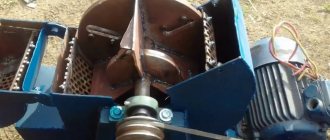
For the broaching mechanism, a roller with a diameter of 25–28 mm is used. On the guide you need to make a groove 0.5 mm wide by 1 mm deep. It is secured to the motor shaft with a nut. The output of the regulator is 6 V, and this is enough for optimal supply. If the lower limit is exceeded, a stabilizer with a lower operating voltage is selected.
The handle holder is machined from textolite sheets 10 mm thick. The seats are made with a drill using drills and an end mill.
The protection hose is held in place on both sides by spacer sleeves. For reliability, there are grooves on the mating parts.
The body will require a 1 m thick sheet of iron with a double flange along the edge. The cooling fan is installed on the rear wall, just opposite the power transformer. The semi-automatic welding machine moves on wheels.
The assembled semiautomatic device is connected to the network for testing. It should not overheat and clearly respond to current adjustment. The transformer insulation is also checked. In case of problems, additional coating is applied. You also need to check the feeding mechanism: how evenly and quickly it feeds the wire. The device has worked faithfully for more than 10 years.
A well-made semi-automatic machine will serve its owner for a long time and reliably, and if you have experience in making a semi-automatic welding machine with your own hands, be sure to share it in the comments to this article.
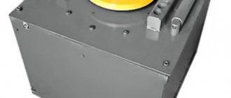
A semi-automatic welding device for household needs can be purchased ready-to-use or completely assembled with your own hands. A homemade semi-automatic machine will cost the performer much less, but its assembly will require certain skills in working with electrical equipment. The appearance of such a welded device is shown in the figure below.
We recommend that everyone who wants to make a semi-automatic machine from an inverter with their own hands first familiarize themselves with the structure of this unit and the operating features of the modules included in it.