Moreover, the use of the latter is now recognized as more reasonable. Installed on the radiator.
The result obtained is associated with the output of a direct welding current, the strength of which is very high and the voltage is low. The bridge modifies the current from alternating to direct.
A voltage-reducing transformer installed behind the inverter unit allows you to obtain a current of sufficient strength at the output of the device so that you can effectively perform welding work with its help. Schemes of homemade and factory welding inverters.
The resistor resistance is 47 ohms. The new version has three pulse transformers, while the old one only has two.
Possible malfunctions and ways to eliminate them Even reliable electronic components can sometimes fail; breakdowns occur when welding inverters are used incorrectly. At the same time, the welding current increases, which exceeds A. Here is the diagram.
To ensure air circulation, an air gap is left between the windings.
The sensor is triggered when the critical heating temperature of any element is reached.
REPAIR OF WELDING INVERTER INTERSKOL ISA 250/10, 6
REPAIR OF WELDING INVERTER MMA-250
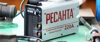
Hello readers of the site Elwo.ru! I read a lot here about the repair of various CAs, and now I want to share my experience myself. That week they brought in a welding inverter for arc welding “Hero MMA MINI-250” for repair.
The device is made using IGBT or (half-bridge) technology.
With a complaint from the owner that the electrode is sticking and does not want to weld. After plugging it into the network and trying to weld the part, nothing worked. And after changing the welding current to a higher one, the welding began to smoke and I heard an electrical crackling sound. The owner said that the cause of the breakdown was the incorrect choice of welding current for the electrode.
Attention: you perform all repair and restoration work on the welding inverter at your own peril and risk.
After disassembly, it was decided to unscrew and check the power supply.
A burnt 150 Ohm 10W resistor was found.
The diode bridge at 100V 35A and the relay at 24 35A turned out to be working.
And in the power supply a swollen capacitor 470 µF x 450 V was found which was replaced.
Next we check the top board.
- Power key driver. (everything possible is checked on this scarf; the resistance should be no more than 10 ohms).
- Power keys.
- 24 V power supply (transistor K2611 or its equivalent and its body kit are checked, see photo).
- Master oscillator. (all field-effect transistors are checked, you can check by turning on welding; when you turn it on and off, a squeak from the generator should appear).
How to check power keys
IRG4PC50UD keys or its equivalents are installed here. Using a multimeter in diode testing mode, you need to ring the legs of the transistor “E” and “C”; in one direction they should ring, but in the other direction they should not ring; the transistor needs to be discharged (short circuit all legs). On legs “G” and “E” the resistance should be infinite, regardless of polarity.
Next, you need to apply 12 volts DC to the “G” - “+” leg and to the “E” “-”. and ring the legs “C” and “E” they should ring. Next, you need to remove the charge from the transistor (short circuit the legs). Legs “C” and “E” should have infinite resistance. If all these conditions are met, then the transistor is working, and so you need to check all the transistors.
Diodes break extremely rarely, but if one breaks, it breaks all the others along with it. An approximate diagram of this MMA-250 welding is here (not complete). After we have replaced all the faulty parts, we assemble the welder in the reverse order and check for functionality. Author of the article 4ei3
Source
What types of inverters are available on the modern market?
For a certain type of welding, you should choose the right inverter equipment, each type of which has a specific electrical circuit and, accordingly, special technical characteristics and functionality.
Inverters produced by modern manufacturers can be used equally successfully both in industrial enterprises and in everyday life. Developers are constantly improving the electrical circuit diagrams of inverter devices, which allows them to be equipped with new functions and improve their technical characteristics.
Inverter devices as the main equipment are widely used to perform the following technological operations:
- consumable and non-consumable electrodes;
- welding using semi-automatic and automatic technologies;
- plasma cutting, etc.
In addition, inverter machines are the most efficient type of equipment used for welding aluminum, stainless steel and other difficult-to-weld metals. Welding inverters, regardless of the features of their electrical circuit, allow you to obtain high-quality, reliable and neat welds made using any technology. At the same time, what is important is that the compact and not too heavy inverter machine, if necessary, can be easily moved at any time to the place where welding work will be performed.
Winding the output choke
One of the simplest and at the same time most useful additions to a welding inverter will be the winding of an inductive coil that smoothes out the DC ripples that inevitably remain when the pulse transformer is operating. The main specificity of this idea is that the choke is made individually for each individual device, and can also be adjusted over time as electronic components degrade or when the power threshold changes.
To make a choke you will need nothing at all: an insulated copper conductor with a cross-section of up to 20 mm 2 and a core, preferably made of ferrite. Either a ferrite ring or an armored transformer core is optimally suited as a magnetic core. If the magnetic core is made of sheet steel, it needs to be drilled in two places with an indentation of about 20–25 mm and tightened with rivets in order to be able to cut the gap without any problems.
The choke begins to work starting from one full turn, but the real result is visible starting from 4–5 turns. During testing, turns should be added until the arc begins to stretch noticeably strongly, preventing separation. When it becomes difficult to cook with separation, you need to remove one turn from the coil and connect a 24 V incandescent lamp in parallel with the choke.
Fine-tuning the throttle is done using a plumber's screw clamp, which can be used to reduce the gap in the core, or a wooden wedge, which can be used to increase this gap. It is necessary to ensure that the lamp burns as bright as possible when igniting the arc. It is recommended to manufacture several chokes to operate in ranges up to 100 A, from 100 to 200 A and more than 200 A.
Read also: How to connect many wires into one
Factors leading to failure of the welding inverter
Situations that can cause the inverter to fail or lead to disruptions in its operation can be divided into two main types:
- associated with incorrect choice of welding mode;
- caused by failure of device parts or their incorrect operation.
The method for identifying an inverter malfunction for subsequent repair comes down to sequential execution of technological operations, from the simplest to the most complex. The modes in which such checks are performed and what their essence is are usually specified in the equipment instructions.
Common inverter malfunctions, their causes and solutions
If the recommended actions do not lead to the desired results and the operation of the device is not restored, most often this means that the cause of the malfunction should be sought in the electronic circuit. The reasons for the failure of its blocks and individual elements may be different. Let's list the most common ones.
- Moisture has penetrated into the inside of the device, which can happen if the body of the device is exposed to precipitation.
- Dust has accumulated on the elements of the electronic circuit, which leads to a disruption in their proper cooling. The maximum amount of dust gets into inverters when they are operated in very dusty rooms or on construction sites. To avoid this condition, the inside of the equipment must be cleaned regularly.
- Failure to comply with the on-time (ON) can lead to overheating of the electronic circuit elements of the inverter and, as a consequence, to their failure. This parameter, which must be strictly observed, is indicated in the technical data sheet of the equipment.
Traces of liquid entering the inverter housing
What does the design of a welding inverter include?
The welding inverter circuit, which determines its technical characteristics and functionality, includes such mandatory elements as:
- a unit that provides electrical power to the power part of the device (it consists of a rectifier, a capacitive filter and a nonlinear charging circuit);
- power part, made on the basis of a single-cycle converter (this part of the electrical circuit also includes a power transformer, a secondary rectifier and an output choke);
- power supply unit for elements of the low-current part of the electrical circuit of the inverter apparatus;
- PWM controller, which includes a current transformer and a load current sensor;
- a block responsible for thermal protection and control of cooling fans (this block of the circuit diagram includes inverter fans and temperature sensors);
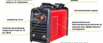
- controls and indications.
Common faults
The most common faults encountered when operating inverters are the following.
Unstable burning of the welding arc or active spattering of metal
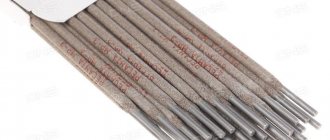
This situation may indicate that the current strength for welding is incorrectly selected. As is known, this parameter is selected depending on the type and diameter of the electrode, as well as on the speed of welding work. If the packaging of the electrodes you are using does not contain recommendations on the optimal current value, you can calculate it using a simple formula: per 1 mm of electrode diameter there should be 20–40 A of welding current. It should also be taken into account that the lower the welding speed, the lower the current should be.
Dependence of electrode diameter on welding current strength
This problem can be due to a number of reasons, most of which are due to low supply voltage. Modern models of inverter devices operate at reduced voltage, but when its value drops below the minimum value for which the equipment is designed, the electrode begins to stick. A drop in voltage at the equipment output can occur if the device blocks are in poor contact with the panel sockets.
Improved heat dissipation
The first drawback that plagues the vast majority of inexpensive inverter devices is a poor heat removal system from power switches and rectifier diodes. It is better to begin improvements in this direction by increasing the intensity of forced airflow. As a rule, case fans are installed in welding machines, powered by 12 V service circuits. In “compact” models, forced air cooling may be completely absent, which is certainly nonsense for electrical equipment of this class.
It is enough to simply increase the air flow by installing several of these fans in series. The problem is that the “original” cooler will most likely have to be removed. To operate effectively in a sequential assembly, fans must have an identical shape and number of blades, as well as rotation speed. Assembling identical coolers into a “stack” is extremely simple; just tighten them with a pair of long bolts along diametrically opposite corner holes. Also, do not worry about the power of the service power supply; as a rule, it is enough to install 3–4 fans.
If there is not enough space inside the inverter housing to install fans, you can install one high on the outside. Its installation is simpler because it does not require connection to internal circuits; power is removed from the power button terminals. The fan, of course, must be installed opposite the ventilation louvers, some of which can be cut out to reduce aerodynamic drag. The optimal direction of air flow is towards the exhaust from the housing.
Read also: Do-it-yourself Supra microwave repair video
The second way to improve heat dissipation is to replace standard aluminum radiators with more efficient ones. A new radiator should be selected with the largest number of fins as thin as possible, that is, with the largest area of contact with air. It is optimal to use computer CPU cooling radiators for these purposes. The process of replacing radiators is quite simple, just follow a few simple rules:
- If the standard radiator is isolated from the flanges of the radio elements with mica or rubber gaskets, they must be preserved when replacing.
- To improve thermal contact, you need to use silicone thermal paste.
- If the radiator needs to be trimmed to fit into the case, the cut fins must be carefully processed with a file to remove all burrs, otherwise dust will accumulate on them abundantly.
- The radiator must be pressed tightly against the microcircuits, so you first need to mark and drill mounting holes on it; you may need to cut a thread in the body of the aluminum base.
Additionally, we note that there is no point in changing the piece heatsinks of separate keys; only the heat sinks of integrated circuits or several high-power transistors installed in a row are replaced.
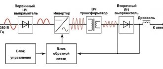
Processes occurring in the electrical circuit of a welding inverter
The circuit allows you to increase the current frequency from the standard 50 Hz to 60–80 kHz. Due to the fact that high-frequency current is subject to regulation at the output of such a device, compact transformers can be effectively used for this. An increase in the frequency of the current occurs in that part of the inverter electrical circuit where the circuit with powerful power transistors is located. As you know, only direct current is supplied to transistors, which is why a rectifier is needed at the input of the device.
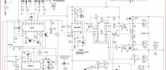
Schematic diagram of the factory welding inverter "Resanta" (click to enlarge)
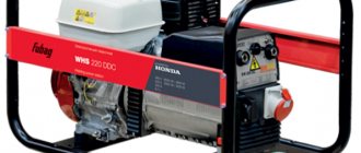
Inverter circuit from the German manufacturer FUBAG with a number of additional functions (click to enlarge)
An example of a circuit diagram of a welding inverter for self-production (click to enlarge)
The electrical circuit diagram of the inverter device consists of two main parts: the power section and the control circuit. The first element of the power section of the circuit is a diode bridge. The task of such a bridge is precisely to convert alternating current into direct current.
In the direct current converted from alternating current in the diode bridge, pulses may occur that need to be smoothed out. To do this, a filter consisting of capacitors of predominantly electrolytic type is installed after the diode bridge. It is important to know that the voltage that comes out of the diode bridge is approximately 1.4 times greater than its value at the input. When converting AC to DC, rectifier diodes become very hot, which can seriously affect their performance.
To protect them, as well as other elements of the rectifier from overheating, radiators are used in this part of the electrical circuit. In addition, a thermal fuse is installed on the diode bridge itself, the task of which is to turn off the power supply if the diode bridge has heated up to a temperature exceeding 80–90 degrees.
High-frequency interference generated during operation of the inverter device can enter the electrical network through its input. To prevent this from happening, an electromagnetic compatibility filter is installed in front of the rectifier block of the circuit. Such a filter consists of a choke and several capacitors.
The inverter itself, which converts direct current into alternating current, but with a much higher frequency, is assembled from transistors using an “oblique bridge” circuit. The switching frequency of transistors, due to which the alternating current is generated, can be tens or hundreds of kilohertz. The high-frequency alternating current thus obtained has a rectangular amplitude.
A voltage-reducing transformer installed behind the inverter unit allows you to obtain a current of sufficient strength at the output of the device so that you can effectively perform welding work with its help. In order to obtain direct current using an inverter apparatus, a powerful rectifier, also assembled on a diode bridge, is connected after the step-down transformer.
Schemes of other models
As previously noted, almost all inverters operate on a similar principle, and the created circuits may differ insignificantly. All welding machines are divided into several main groups:
- To carry out electric arc welding when using electrodes coated with a special composition, MMA type equipment is used. This scheme is characterized by high efficiency, and the design is light in weight.
- To use refractory electrodes, MMA+TIG welding equipment is used. They can operate in an environment of inert gases.
- On production lines there are units with semi-automatic bar feeding. In this case, work is usually carried out in an environment of inert gases or in special baths.
- For forging or other repairs, spot welding is used.
The ARC 160 model, the circuit of which is quite complex, can be used for a wide variety of work. Unlike the arc 140, the new model's circuit has no major drawbacks.
Welding inverter TORUS 250
The Torus 250 version consists of the following elements:
- A clock type generator built on a TL microcircuit. It is worth considering that the powerful inverter circuit does not provide for the use of PWM, but the microcircuit has two comparators with thermal protection sensors.
- The protection system and control module are made on the basis of LM. The sensor that determines the current parameters is placed on a ferrite ring with a winding.
- The circuit also includes two output drivers built on IR
A separate category includes a welding inverter circuit using thyristors, which has become very widespread.
Repair of Torus 250 should be carried out by opening the structure and visually inspecting the main elements. In this case they are as follows:
- The output type rectifier is represented by a separate board on which two radiators are placed. They serve as a base for placing diode assemblies. The module also includes one transformer and a choke. The number of elements in the output rectifier largely depends on the specific assembly.
- The switch module is represented by four transistors in each of the four groups. In order to reduce the degree of heating, they are all placed on separate radiators, which are insulated with special gaskets.
- A powerful diode bridge is used as the output rectifier. In the case under consideration, it is located at the bottom of the structure. This model is equipped with an extremely reliable and practical bridge, which is difficult to burn if the cooling system is working properly.
- The control chip is the main design element. As a rule, the durability of the entire device depends on its correct operation. You can check the unit yourself only if you have a special oscilloscope and the appropriate skills to work with it.
- Housing with cooling fan. As a rule, the cooling unit fails only in the event of mechanical impact.
Read also: How to solder brown copper
To diagnose many elements, it is necessary to dismantle them. That is why it is best to entrust the work to professionals, since incorrect assembly can lead to significant problems.
The welding inverter SAI 200, the circuit of which does not differ significantly from devices of a similar type, is used for manual arc welding and surfacing when using stick electrodes. RDMMA 200 belongs to a new type of equipment that is created without the use of transformers. Due to this, more accurate and smooth adjustment of current indicators is possible, and there is no strong noise during operation.
In conclusion, we note that the above information determines the complexity of the design of welding inverters. At the same time, manufacturers do not distribute detailed diagrams of devices, which complicates maintenance and repair. Despite the use of a similar circuit when creating almost all inverters, they differ significantly from each other. That is why, before carrying out any work, you need to familiarize yourself in detail with the design features of the device.
If you find an error, please select a piece of text and press Ctrl+Enter.
The characteristics of most budget inverters cannot be called outstanding, but at the same time, few will refuse the pleasure of using equipment with a significant margin of reliability. Meanwhile, there are many ways to improve an inexpensive welding inverter.
Basic malfunctions of the welding inverter
Welding inverter sparks, but does not weld
This malfunction is quite common in budget models. The equipment generates a discharge, but an electric arc does not ignite. More precisely, it lights up for a very short period of time and immediately goes out. There are several explanations for this breakdown.
Troubleshooting should begin by checking the welding cables. As practice shows, in most cases the reason lies precisely in them. Even in the case when obvious sins were not found, you should not calm down. It is advisable to take new conductors and try to ignite the arc again. If nothing has changed, then you need to make sure that all connectors are secure.
Also, the reason may lie in the electrolytic capacitors that are used in the converter circuit. They are easy to replace yourself. If you don’t have the skills, you can turn to more experienced friends or specialists. When the situation has not improved, then it’s time to pay attention to the wires of the package. It may be that they are burnt and require replacement.
If in this case it was not possible to repair the welding machine, then it should be taken to a service center. There can be many reasons for such a problem, and it is very difficult to find them by brute force. Having carried out diagnostics, specialists will be able to quickly determine the breakdown and offer options for its elimination.
The welding machine turns on, but does not weld
Sometimes a situation arises when the inverter is connected to the network, but does not generate a welding arc. All indicators and devices show that they are working normally, but the device itself does not cook at this time. The most likely reason is that the device has overheated. This will be discussed below.
Another reason could be faulty cables. It is worth trying to connect new lines and try to remove the welding arc again.
Overheat
When the inverter overheats, it begins to cook poorly or does not generate an arc at all. This happens when you have to cook without a break for more than 10 minutes. Most models sold on the market are equipped with overheating protection. But there are times when it doesn't work. The inverter remains on but does not operate. Solving the problem is not difficult. It is enough to turn off the device for half an hour. During this period of time it will cool down, return to normal and you can continue working.
Welding inverter does not turn on/does not work
The problem does not occur very rarely. The equipment is connected to the power supply network, but shows absolutely no signs of life. There may be several reasons for this. Most often, the power supply network is to blame: the voltage has fallen below the minimum permissible level and is not enough to initialize the welding machine. You can solve the problem by purchasing a voltage stabilizer. Subsequently, welding is connected through it and works normally.
Welding current indication
Even if a digital current setting indicator is installed on the inverter, it does not show its real value, but a certain service value, scaled for visual display. The deviation from the actual current value can be up to 10%, which is unacceptable when using special brands of electrodes and working with thin parts. You can get the actual value of the welding current by installing an ammeter.
A digital ammeter of the SM3D type will cost around 1 thousand rubles; it can even be neatly built into the inverter housing. The main problem is that measuring such high currents requires a shunt connection. Its cost is in the range of 500–700 rubles for currents of 200–300 A. Please note that the type of shunt must comply with the recommendations of the ammeter manufacturer; as a rule, these are 75 mV inserts with an intrinsic resistance of about 250 μOhm for a measurement limit of 300 A.
The shunt can be installed either on the positive or negative terminal from inside the housing. Typically, the size of the connecting bus is sufficient to connect an insert about 12–14 cm long. The shunt cannot be bent, so if the length of the connecting bus is not enough, it must be replaced with a copper plate, a pigtail of cleaned single-wire cable, or a piece of welding conductor.
The ammeter is connected with measuring outputs to the opposite terminals of the shunt. Also, for the digital device to operate, it is necessary to supply a supply voltage in the range of 5–20 V. It can be removed from the fan connection wires or found on the board at points with potential for powering control chips. The ammeter's own consumption is negligible.
Inverter protection and control elements
Several elements in its circuit diagram allow you to avoid the influence of negative factors on the operation of the inverter.
To ensure that transistors that convert direct current into alternating current do not burn out during their operation, special damping (RC) circuits are used. All electrical circuit blocks that operate under heavy load and become very hot are not only provided with forced cooling, but are also connected to temperature sensors that turn off their power if their heating temperature exceeds a critical value.
Due to the fact that the filter capacitors, after being charged, can produce a high current, which can burn the inverter transistors, the device must be provided with a smooth start. For this purpose, stabilizers are used.
The circuit of any inverter has a PWM controller, which is responsible for controlling all elements of its electrical circuit. From the PWM controller, electrical signals are sent to a field-effect transistor, and from it to an isolation transformer, which simultaneously has two output windings. The PWM controller, through other elements of the electrical circuit, also supplies control signals to the power diodes and power transistors of the inverter unit. In order for the controller to effectively control all elements of the inverter's electrical circuit, it is also necessary to supply electrical signals to it.
To generate such signals, an operational amplifier is used, the input of which is supplied with the output current generated in the inverter. If the values of the latter diverge from the specified parameters, the operational amplifier generates a control signal to the controller. In addition, the operational amplifier receives signals from all protective circuits. This is necessary so that he can disconnect the inverter from the power supply at the moment when a critical situation arises in its electrical circuit.
Typical circuit and principle of operation of the inverter
The more expensive the welding inverter, the more auxiliary units in its circuit that are involved in the implementation of special functions. But the power converter circuit itself remains virtually unchanged even with expensive equipment. The stages of transformation of mains electric current into welding current are quite easy to trace - at each of the main nodes of the circuit a certain part of the overall process occurs.
From the network cable, through a protective switch, voltage is supplied to a rectifying diode bridge coupled with high-capacity filters. In the diagram, this area is easy to notice; there are impressive-sized “banks” of electrolytic capacitors located here. The rectifier has one task - to “turn” the negative part of the sine wave symmetrically upward, while the capacitors smooth out the ripples, bringing the direction of the current almost to a pure “constant”.
Scheme of operation of the welding inverter
Next in the diagram is the inverter itself. This part is also easy to identify; the largest aluminum radiator is located here. The inverter is built on several high-frequency field-effect transistors or IGBT transistors. Quite often, several power elements are combined in a common housing. The inverter again converts direct current into alternating current, but at the same time its frequency is significantly higher - about 50 kHz. This chain of transformations allows the use of a high-frequency transformer, which is several times smaller and lighter than a conventional one.
The output rectifier removes the voltage from the step-down transformer, because we want to weld with direct current. Thanks to the output filter, the nature of the current changes from a high-frequency pulsating current to an almost straight line. Naturally, in the considered chain of transformations there are many intermediate links: sensors, control and control circuits, but their consideration goes far beyond the scope of amateur radio electronics.
Design of the welding inverter: 1 - filter capacitors; 2 - rectifier (diode assembly); 3 - IGBT transistors; 4 - fan; 5 - step-down transformer; 6 — control board; 7 - radiators; 8 - throttle
How to check power keys
IRG4PC50UD keys or its equivalents are installed here. Using a multimeter in diode testing mode, you need to ring the legs of the transistor “E” and “C”; in one direction they should ring, but in the other direction they should not ring; the transistor needs to be discharged (short circuit all legs). On legs “G” and “E” the resistance should be infinite, regardless of polarity.
Next, you need to apply 12 volts DC to the “G” - “+” leg and to the “E” “-”. and ring the legs “C” and “E” they should ring. Next, you need to remove the charge from the transistor (short circuit the legs). Legs “C” and “E” should have infinite resistance. If all these conditions are met, then the transistor is working, and so you need to check all the transistors.
Diodes break extremely rarely, but if one breaks, it breaks all the others along with it. An approximate diagram of this MMA-250 welding is here (not complete). After we have replaced all the faulty parts, we assemble the welder in the reverse order and check for functionality. Author of the article 4ei3
Advantages and disadvantages of inverter-type welding machines
The devices that replaced the usual transformers have a number of significant advantages.
- Thanks to a completely different approach to the formation and regulation of welding current, the weight of such devices is only 5–12 kg, while welding transformers weigh 18–35 kg.
- Inverters have very high efficiency (about 90%). This is explained by the fact that they spend significantly less excess energy on heating the components. Welding transformers, unlike inverter devices, get very hot.
- Due to such high efficiency, inverters consume 2 times less electrical energy than conventional transformers for welding.
- The high versatility of inverter machines is explained by the ability to regulate the welding current over a wide range with their help. Thanks to this, the same device can be used for welding parts made of different metals, as well as for welding using different technologies.
- Most modern inverter models are equipped with options that minimize the impact of welder errors on the technological process. Such options, in particular, include “Anti-stick” and “Arc Force” (fast ignition).
- Exceptional stability of the voltage supplied to the welding arc is ensured by the automatic elements of the inverter electrical circuit. In this case, automation not only takes into account and smoothes out differences in input voltage, but also corrects even such interference as the attenuation of the welding arc due to strong wind.
- Welding using inverter equipment can be performed with any type of electrode.
- Some models of modern welding inverters have a programming function, which allows you to accurately and quickly configure their modes when performing a certain type of work.
Modern welding work is carried out using special inverters. Previously, conventional transformers, which are characterized by lower efficiency, were used for such metal processing. The schematic diagram of a welding inverter may differ slightly, but they are all characterized by lightness and compactness. Only by taking into account the design features can the welding inverter be repaired and fine-tuned.
File description:
Device type: welding inverter
Manufacturer: SVAROG
Model: SVAROG TIG 250 (R22)
Instructions in Russian
File format: pdf, size: 901.66 kB
To familiarize yourself with the instructions, you must click on the “DOWNLOAD” link to download the pdf file. If there is a “VIEW” button, then you can simply view the document online.
For convenience, you can save this page with the instruction manual file to your “favorites” list directly on the site (available for registered users).
The TIG DC250 welding inverter is designed for use as a power source for TIG argon arc welding. The welding inverter can be used either independently or as part of automatic installations.
Features of TIG welding machine DC250
- Output current range from 1 to 250A with 1A accuracy
- Duty cycle 100% over the entire range of output currents
- High output voltage, allowing you to work with welding cables up to 300 meters
- Absence of output current and voltage ripple both in the mains frequency range and in the inverter operating frequency range
- Short settling time of the output current, allowing for pulse formation of less than 1 ms
- Dial indicators of welding current and arc voltage, tested by ROSTEST
- Protection against overheating and phase imbalance
- Control by remote control
- Simple control when integrated into welding complexes using a discrete “switch on” signal and an analogue “Current” signal
- Built-in or external oscillator
- Built-in or external shielding gas flow control system
- Ability to operate up to 4 sources in parallel with output current up to 1000A
- Standard 4U 19″ rackmount enclosure
- Modification for alternating current DC160AC
- Built-in modulator to change the polarity of the output signal
To ensure high reliability of the current source, a phase-shifting bridge circuit with two back-to-back transreactors and doubling the output current is used in the power section. Such a power circuit and the use of a microprocessor control system made it possible to obtain a welding source with a full set of service functions and an output current from 1 to 300 amperes with a ripple of no more than 0.5A and an output voltage of at least 50V at maximum current. The time to establish the current at the 90% level does not exceed 0.2 ms, which makes it possible to implement any pulse modes.
Tig welding machine diagram DC250
The main purpose of the source is to work as part of automated and robotic welding complexes. Unlike foreign analogues, the control source does not have complex digital buses with closed protocols, but is controlled by two signals: an analog current command and a discrete current switch signal. When using sources Fronius, ESAB, KEMPPI, LORCH, LINCOLN ELECTRIC and others as part of automated complexes, a problem arises with controlling the output current with a smooth increase in current at the beginning of welding, a smooth decrease for filling a crater, or in step-pulse modes that require synchronous control of current and welding speed , filler wire speed and transverse vibrations. As a rule, all foreign manufacturers of welding sources themselves or in cooperation produce complex welding complexes and impose their automation services when purchasing sources. In this case, all special modes are provided through special high-speed buses between the welding source and the rest of the equipment. However, when these welding sources are integrated into domestic automated systems being developed, communication with the sources can only be organized through special interface modules that provide a minimum set of control functions. In addition, these modules, as a rule, have a response delay to control signals of the order of 100-300 ms, which does not allow the implementation of complex control laws. The DC250LE welding machine allows it to be used in any automated and robotic welding complexes due to simple analog current control with a delay of no more than 0.2 ms.
Read also: Drl 250 lamp technical characteristics
An important advantage of the welding machine is the use of dial indicators of output current and voltage, which allows the source to be used on objects that require the use of verified measuring instruments. Real current and voltage values are additionally output to the connector in analog form.
Technical characteristics of the welding inverter TIG DC250
| Parameter | Meaning |
| Supply voltage of the primary three-phase network, V | 380±15% |
| Maximum power consumption, kW | 14 |
| Rated output current, A | 250 |
| PN at rated current, % | 100 |
| Maximum output current, A | 300 |
| PN at rated current, % | 60 |
| Output current adjustment range, A | 1…300 |
| Open circuit voltage, V | 75±5 |
| Output voltage at current 250A, V | 0. 52 |
| Ambient temperature, °C | -10…+45 |
| Overall dimensions (lshv), mm | 520x440x180 |
| Weight, kg | 22 |
First digit: 0 - without external control panel, 1 - external control panel in continuous mode, 2 - external control panel with pulse mode.
Second digit: 0 – without built-in oscillator, 1 – built-in oscillator
Third digit: 0 – without gas control system, 1 – gas valve for switching on protective gas, 2 – gas flow control system from 1 to 25 l/min.
DC250 Tig Welding Machine
Declaration of conformity TS N RU D-RU.AL92.V.18342
The DC250 source has a minimum output current settling time of no more than 200 µs. The oscillogram shows the shape of the output voltage when the source is loaded in pulse mode onto the ballast rheostat. This makes it possible to implement technologies for welding thin products that are not available to other welding sources that have a current settling time of a few milliseconds.
Output voltage of the welding source when operating in pulse mode.
Features of maintenance and repair of inverter devices
Repairing an inverter-type welding machine has a number of features, which is explained by the complexity of the design of such a device. Any inverter, unlike other types of welding machines, is electronic, which requires specialists involved in its maintenance and repair to have at least basic radio engineering knowledge, as well as skills in handling various measuring instruments - a voltmeter, digital multimeter, oscilloscope, etc. .
Elements of the electrical circuit of welding inverters
The electrical circuit diagram of an inverter welding machine involves a combination of several elements that are interconnected. The main ones can be called:
- The block responsible for supplying energy to the power section. This element is represented by a combination of several devices that are capable of changing current parameters to the required values. Typically, a capacitive filter and a rectifier are included.
- The device includes a power transformer. The power supply of the welding inverter also includes a 4n90 transistor.
- A separate element is responsible for powering the low-current part of the structure.
- To control the main parameters, a PWM controller is installed. It is represented by a combination of a load current sensor and a transformer.
- A separate block is responsible for protecting the structure from heat. When electrical current passes, some components may become very hot. Therefore, an additional cooling module is installed, represented by a fan and a temperature sensor.
- Control units that allow you to set basic parameters, as well as display elements.
DIY welding inverter repair
Over the past couple of decades, there have been major changes in the development of welding technologies. The most popular equipment has become the inverter - a technologically advanced and modern device that has many advantages compared to classic welding. In addition to more advanced technical solutions from transformers and rectifiers, it also compares favorably in cost.
At the center of the technical solution is a microcircuit. It was these small elements that gave manufacturers the opportunity to pack equipment with extensive functionality and radically reduce the weight and size of the installation. But there is also another side to the coin. It lies in the fact that technically more complex devices fail more often. So, the main faults and repairs of inverter welding machines with your own hands.
Swaris device diagrams
The welding machine Svaris 200 is characterized by ease of use and low cost. Already the Swaris 160 models had high performance characteristics, and the new version was improved. The circuit of the inverter welding machine determines the following operational characteristics:
- The maximum consumption is 5 kW.
- Welding current can vary from 20-200 A.
- The open circuit voltage indicator is 62 V.
- Efficiency rate 85%.
- Recommended electrodes 1.6-5.0.
In general, we can say that the inverter is made according to the classical scheme, which was discussed above.
Homemade toroidal welding machine
Scheme of a homemade toroidal welding machine.
U-shaped and W-shaped transformers are significantly inferior to toroids in terms of weight and size. A toroidal welding machine is one and a half times lighter than its W-shaped counterpart, but the main difficulty in making it yourself lies in the lack of the necessary iron. Craftsmen share recommendations for making a transformer from an industrial CA that has exhausted its service life. A similar replacement would be the TCA 310 or TS 270 transformer. Its U-shaped plates are “halved” with a chisel and adjusted on an anvil.
Welding machines of this type are assembled from 45 x 9 cm plates:
- a plate riveted hoop with a diameter of 26 cm is filled with plates end to end (the work is done by two people, a partner fixes the core being assembled, preventing the plates from straightening);
- when the internal diameter of the structure reaches 12 cm, the set stops;
- Details are cut out of electrical cardboard: a strip 9 cm wide, rings with an internal diameter of 11 cm, an external diameter of 27 cm;
- the rings are applied to the sides of the structure assembled at the first stage and wrapped with fabric tape;
- winding I is laid on electrical tape - 170 turns (for 220 V) of wire with a diameter of 2 mm, grade PEV-2;
- winding II is laid on top of it - 30 turns of wire with a diameter of 15-20 mm, grade PEV-3;
- winding III - 30 turns with MGTF 0.35 wire;
- insulation from each other with tape, the software is checked for the XX current: if it is less than 1-2 A, several turns are unwound; if the XX current is greater than 2 A, two turns are added.
This welding machine has an original control circuit in the form of a phase regulator. The voltage removed from winding III is rectified by a diode bridge. The capacitor is charged through resistors up to 6 V, then a breakdown occurs through a dinistor assembled from a thyristor and a zener diode. The diode with the thyristor opens. The last resistor in the circuit limits the current; when the alternating current wave is negative, the response thyristor and diode open. Welding machines of this design are tuned with a resistor.
To create a welding machine, resistors with a power of 10 W or more are required.
The scheme uses:
- diodes for a current of 160-250 A, mounted on radiators with an area of 100 cm2;
- capacitor K50-6;
- resistors with a power of 10 W;
- thyristors KU202 or KU201.
The welding machine confidently welds with electrodes with a diameter of 4 mm and cuts metal. You can make a holder for it yourself from an equal angle corner 10 cm long (shelves 2 cm each). A hole with a diameter of 4.1 mm is drilled 1 cm from the edge of the corner in the very corner, through which the burnt electrode can be pushed out with a new electrode. The lower part of the shelves will be narrowed according to the welder's hand. A wire is welded into the inner corner, bent vertically upward from it. A piece of rubber hose is placed on the structure from below. During operation, the electrode is inserted between the edges of the angle and pressed against them with a piece of welded wire.
Inverter 3200 and 4000 circuits
For manual arc welding, you can use the Inverter 4000 or 3200. Both machines have an almost identical design, which provides the following functions:
- Protection against electrode sticking effect.
- Protecting key components from severe voltage surges.
- Control of basic arc parameters.
- Built-in cooling element with control sensors.
During the manufacture of inverters, IP21 protection was provided. The power of the device is 5.3 kW, powered by a standard power supply network. The detailed diagram of inverter 3200 pro determines the very attractive properties of these models, due to which they have become widespread.
Machine for welding from car batteries
In order to invent a diesel generator for a welding machine, it is necessary to connect a pair of batteries in a certain sequence.
The welding machine seriously loads the household electrical network, providing a voltage surge of 30 V at a load of 3.5 kW. Instead of purchasing a welding diesel generator, the craftsmen created an original device circuit, the basis of which is 3-4 series-connected batteries from a passenger car. The capacity of each of them must be at least 55-190 A/h; reliable clamps must be used to combine them into a common circuit.
This scheme is indispensable in field conditions, since even used batteries delivered to the site by a passenger vehicle will help out. It is necessary to take into account the strong heating of battery cases after several hours of operation, check the level and density of the electrolyte daily with constant use. In hot weather, water evaporates rapidly from the electrolyte, so control devices (hydrometer), distilled water, and acid should be kept at hand.
Welding machines of this type simply need to be charged at night by connecting the appropriate device to a common circuit so that all batteries are charged at once. When welding with electrodes with a diameter of 3 mm, the working current is no more than 90-120 A, which does not exceed half the power. The electrolyte does not boil due to its high heat capacity. The output voltage depends entirely on the number of batteries connected to the circuit and is 42-54 V.
Tags: , automatic, ampere, beat, sconce, view, internal, generator, engine, house, , clamp, insulation, pulse, cable, like, computer, capacitor, , magnet, installation, power, load, voltage, oscilloscope, variable, transfer, strip, polarity, constant, rule, principle, wire, start, , work, size, calculation, regulator, resistor, row, garden, homemade, network, connection, means, zener diode, circuit, ten, type, current , transistor, transformer, , installation, filter, photo, shield, effect