The circuit of a welding inverter is fundamentally different from the design of its predecessor, the welding transformer. The basis of the design of previous welding machines was a step-down transformer, which made them large and heavy. Modern welding inverters, thanks to the use of advanced developments in their production, are lightweight and compact devices characterized by wide functionality.
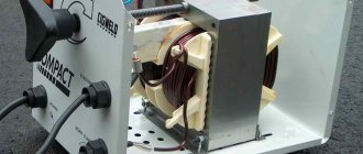
Welding inverter without cover
The main element of the electrical circuit of any welding inverter is a pulse converter that generates high-frequency current. It is thanks to this that the use of an inverter makes it possible to easily ignite the welding arc and maintain it in a stable state throughout the welding process. The welding inverter circuit, depending on the model, may have certain features, but the principle of its operation, which will be discussed below, remains unchanged.
What types of inverters are available on the modern market?
For a certain type of welding, you should choose the right inverter equipment, each type of which has a specific electrical circuit and, accordingly, special technical characteristics and functionality.
Inverters produced by modern manufacturers can be used equally successfully both in industrial enterprises and in everyday life. Developers are constantly improving the electrical circuit diagrams of inverter devices, which allows them to be equipped with new functions and improve their technical characteristics.
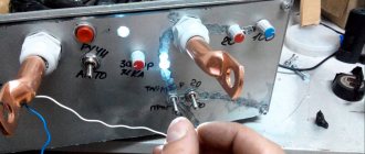
The number of connectors and controls on the front panel speaks volumes about the capabilities of the welding inverter
Inverter devices as the main equipment are widely used to perform the following technological operations:
- electric arc welding with consumable and non-consumable electrodes;
- welding using semi-automatic and automatic technologies;
- plasma cutting, etc.
In addition, inverter machines are the most efficient type of equipment used for welding aluminum, stainless steel and other difficult-to-weld metals. Welding inverters, regardless of the features of their electrical circuit, allow you to obtain high-quality, reliable and neat welds made using any technology. At the same time, what is important is that the compact and not too heavy inverter machine, if necessary, can be easily moved at any time to the place where welding work will be performed.
Mobility is one of the advantages of inverter devices
What does the design of a welding inverter include?
The welding inverter circuit, which determines its technical characteristics and functionality, includes such mandatory elements as:
- a unit that provides electrical power to the power part of the device (it consists of a rectifier, a capacitive filter and a nonlinear charging circuit);
- power part, made on the basis of a single-cycle converter (this part of the electrical circuit also includes a power transformer, a secondary rectifier and an output choke);
- power supply unit for elements of the low-current part of the electrical circuit of the inverter apparatus;
- PWM controller, which includes a current transformer and a load current sensor;
- a block responsible for thermal protection and control of cooling fans (this block of the circuit diagram includes inverter fans and temperature sensors);
- controls and indications.
Tools required to make an inverter
To assemble a welding inverter from a power supply with your own hands, you will need the following tools:
TL494 voltage feedback circuit in a computer power supply.
- soldering iron;
- screwdrivers with different tips;
- pliers;
- wire cutters;
- drill or screwdriver;
- crocodiles;
- wires of the required cross-section;
- tester;
- multimeter;
- consumables (wires, solder for soldering, electrical tape, screws and others).
To create a welding machine from a computer power supply, you need materials to create a printed circuit board, getinaks, and spare parts. To reduce the amount of work, you should go to the store for ready-made electrode holders. However, you can make them yourself by soldering crocodiles to wires of the required diameter. It is important to observe polarity when doing this work.
How does a welding inverter work?
The formation of a high current, with the help of which an electric arc is created to melt the edges of the parts being joined and the filler material, is what any welding machine is designed for. For the same purposes, an inverter apparatus is also needed, which allows the generation of welding current with a wide range of characteristics.
In its simplest form, the principle of operation of the inverter looks like this.
- Alternating current with a frequency of 50 Hz from a regular electrical network is supplied to the rectifier, where it is converted into direct current.
- After the rectifier, the direct current is smoothed using a special filter.
- From the filter, direct current flows directly to the inverter, whose task is to convert it again into alternating current, but at a higher frequency.
- After this, using a transformer, the voltage of the alternating high-frequency current is reduced, which makes it possible to increase its strength.
Block diagram of an inverter type welding machine
In order to understand the importance of each element of the electrical circuit diagram of an inverter device, it is worth considering its operation in more detail.
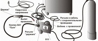
Repair or modification of the electrode wire feed speed device
Almost all semi-automatic welding machines of any type are characterized by low reliability of the wire feed mechanism. It is this place that is the most vulnerable in their design. It also leads to frequent breakdowns of the unit.
Failure of this unit can either disrupt the quality of operation of the device or lead to more serious problems in its operation.
Features of the device of a semi-automatic welder.
In the first case, you can get by with simply replacing the wire. However, valuable time will still be wasted on cleaning the contact area of the nozzle, due to the fixation of the wire during feeding.
The occurrence of malfunctions, first of all, indicates a violation of the feed rate. The way out of this situation will be to refine this mechanism.
If it was decided to make a semi-automatic machine yourself from an inverter with your own hands, then the welding wire feeder can also be made by yourself.
For these purposes we will need two bearings. Another necessary part is a small electric motor.
A roller should be installed on the shaft of the electric motor. The radius of this part is about 12.5 millimeters. Bearings are mounted on metal plates. It is between the plates that the electric motor is located.
The assembly of this mechanism should be carried out on a textolite plate with a thickness of about five millimeters. A spool of welding wire is also installed on it.
If assembled correctly and without any errors, the homemade device will last quite a long time.
Processes occurring in the electrical circuit of a welding inverter
The circuit of an inverter-type welding machine allows you to increase the current frequency from the standard 50 Hz to 60–80 kHz. Due to the fact that high-frequency current is subject to regulation at the output of such a device, compact transformers can be effectively used for this. An increase in the frequency of the current occurs in that part of the inverter electrical circuit where the circuit with powerful power transistors is located. As you know, only direct current is supplied to transistors, which is why a rectifier is needed at the input of the device.
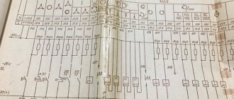
Schematic diagram of the factory welding inverter "Resanta" (click to enlarge)
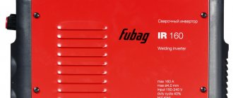
Inverter circuit from the German manufacturer FUBAG with a number of additional functions (click to enlarge)
An example of a circuit diagram of a welding inverter for self-production (click to enlarge)
The electrical circuit diagram of the inverter device consists of two main parts: the power section and the control circuit. The first element of the power section of the circuit is a diode bridge. The task of such a bridge is precisely to convert alternating current into direct current.
In the direct current converted from alternating current in the diode bridge, pulses may occur that need to be smoothed out. To do this, a filter consisting of capacitors of predominantly electrolytic type is installed after the diode bridge. It is important to know that the voltage that comes out of the diode bridge is approximately 1.4 times greater than its value at the input. When converting AC to DC, rectifier diodes become very hot, which can seriously affect their performance.
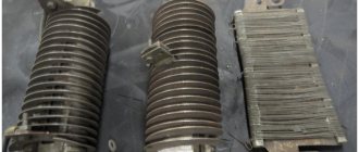
Components of a welding inverter using the example of a homemade machine
To protect them, as well as other elements of the rectifier from overheating, radiators are used in this part of the electrical circuit. In addition, a thermal fuse is installed on the diode bridge itself, the task of which is to turn off the power supply if the diode bridge has heated up to a temperature exceeding 80–90 degrees.
High-frequency interference generated during operation of the inverter device can enter the electrical network through its input. To prevent this from happening, an electromagnetic compatibility filter is installed in front of the rectifier block of the circuit. Such a filter consists of a choke and several capacitors.
Inverter power supply
The inverter itself, which converts direct current into alternating current, but with a much higher frequency, is assembled from transistors using an “oblique bridge” circuit. The switching frequency of transistors, due to which the alternating current is generated, can be tens or hundreds of kilohertz. The high-frequency alternating current thus obtained has a rectangular amplitude.
A voltage-reducing transformer installed behind the inverter unit allows you to obtain a current of sufficient strength at the output of the device so that you can effectively perform welding work with its help. In order to obtain direct current using an inverter apparatus, a powerful rectifier, also assembled on a diode bridge, is connected after the step-down transformer.
Transistors for the power module of the welding inverter
Operating principle of semi-automatic welding machine
The essence of the operation of this unit comes down to the following principle: current is supplied to the rectifier, resulting in a pulsating voltage that is smoothed by a filter. As a result of these processes, a direct current is obtained at the output.
Then, with the help of special transistors, the direct current is converted back into alternating current. However, its frequency is already different from the original one, corresponding to the network one. Usually its value is twenty hertz and higher.
At the same time, the voltage becomes smaller and amounts to 70-90 V, and the current increases up to two hundred amperes.
Based on the parameters described above, it becomes clear: homemade semiautomatic welding machines are capable of providing the same characteristics as most other similar devices.
On the other hand, such units are not without their drawbacks. Their design provides for the presence of complex electrical circuits, which means repairing these devices is more complicated.
Semi-automatic for welding work.
If you have decided to make a semi-automatic welding machine with your own hands, then you should, first of all, decide on some of its functions. For example, the presence or absence of the ability to work in a protective gas environment will be a significant factor.
Modern devices have this function and provide operation in MMA mode. Of course, welding in the absence of a protective atmosphere will be of lower quality.
The operation of a semi-automatic device involves the use of a protective atmosphere, which is carbon dioxide. You will also need a welding wire that is automatically fed into the welding area.
As you can see, the operating process of a semiautomatic device is much more complicated than an inverter. But the first one is more universal and allows you to solve a wider range of problems. In connection with all of the above, converting a welding inverter into a semi-automatic device is a very profitable and relevant idea.
Inverter protection and control elements
Several elements in its circuit diagram allow you to avoid the influence of negative factors on the operation of the inverter.
To ensure that transistors that convert direct current into alternating current do not burn out during their operation, special damping (RC) circuits are used. All electrical circuit blocks that operate under heavy load and become very hot are not only provided with forced cooling, but are also connected to temperature sensors that turn off their power if their heating temperature exceeds a critical value.
Radiators and cooling fans take up significant space inside the inverter
Due to the fact that the filter capacitors, after being charged, can produce a high current, which can burn the inverter transistors, the device must be provided with a smooth start. For this purpose, stabilizers are used.
The circuit of any inverter has a PWM controller, which is responsible for controlling all elements of its electrical circuit. From the PWM controller, electrical signals are sent to a field-effect transistor, and from it to an isolation transformer, which simultaneously has two output windings. The PWM controller, through other elements of the electrical circuit, also supplies control signals to the power diodes and power transistors of the inverter unit. In order for the controller to effectively control all elements of the inverter's electrical circuit, it is also necessary to supply electrical signals to it.
To generate such signals, an operational amplifier is used, the input of which is supplied with the output current generated in the inverter. If the values of the latter diverge from the specified parameters, the operational amplifier generates a control signal to the controller. In addition, the operational amplifier receives signals from all protective circuits. This is necessary so that he can disconnect the inverter from the power supply at the moment when a critical situation arises in its electrical circuit.
Advantages and disadvantages of inverter-type welding machines
Inverter welding machines, which replaced the usual transformers, have a number of significant advantages.
- Thanks to a completely different approach to the formation and regulation of welding current, the weight of such devices is only 5–12 kg, while welding transformers weigh 18–35 kg.
- Inverters have very high efficiency (about 90%). This is explained by the fact that they spend significantly less excess energy on heating the components. Welding transformers, unlike inverter devices, get very hot.
- Due to such high efficiency, inverters consume 2 times less electrical energy than conventional transformers for welding.
- The high versatility of inverter machines is explained by the ability to regulate the welding current over a wide range with their help. Thanks to this, the same device can be used for welding parts made of different metals, as well as for welding using different technologies.
- Most modern inverter models are equipped with options that minimize the impact of welder errors on the technological process. Such options, in particular, include “Anti-stick” and “Arc Force” (fast ignition).
- Exceptional stability of the voltage supplied to the welding arc is ensured by the automatic elements of the inverter electrical circuit. In this case, automation not only takes into account and smoothes out differences in input voltage, but also corrects even such interference as the attenuation of the welding arc due to strong wind.
- Welding using inverter equipment can be performed with any type of electrode.
- Some models of modern welding inverters have a programming function, which allows you to accurately and quickly configure their modes when performing a certain type of work.
Like any complex technical devices, welding inverters have a number of disadvantages that you also need to be aware of.
- Inverters are highly expensive, 20–50% higher than the cost of conventional welding transformers.
- The most vulnerable and often failing elements of inverter devices are transistors, the cost of which can be up to 60% of the price of the entire device. Accordingly, repairing a welding inverter is quite an expensive undertaking.
- Due to the complexity of their electrical circuitry, inverters are not recommended for use in bad weather conditions and at low temperatures, which seriously limits their scope of application. In order to use such a device in field conditions, it is necessary to prepare a special closed and heated area.
When welding work performed using an inverter, long wires cannot be used, as they induce interference that negatively affects the operation of the device. For this reason, the wires for inverters are made quite short (about 2 meters), which makes welding work somewhat inconvenient.
How to use a homemade device
After connecting a homemade device to the circuit, the controller will automatically set a certain current strength. If the wire voltage is less than 100 Volts, this indicates a malfunction of the device. You will have to disassemble the device and recheck the correct assembly again.
Using this type of welding machine, you can solder not only ferrous, but also non-ferrous metals. In order to assemble a welding machine, you will need not only knowledge of the basics of electrical engineering, but also free time to implement the idea.
Inverter welding is an indispensable thing in any owner’s garage, so if you have not yet acquired such a tool, then you can make it yourself.
The characteristics of most budget inverters cannot be called outstanding, but at the same time, few will refuse the pleasure of using equipment with a significant margin of reliability. Meanwhile, there are many ways to improve an inexpensive welding inverter.