A lathe allows you to turn parts of various geometries. However, it is best to start by creating a cone. To do this you will need:
- the lathe itself;
- persistent cutter;
- rotatable caliper for precise longitudinal feed.
Naturally, the blank rod (herringbone) must already be properly prepared for turning the head onto the cone. It is recommended to carry out the work on working equipment. You can find interesting sales offers on the Internet (price negotiable) - https://stankosib.ru/bu-stanki-prodazha.
How to sharpen a taper on a lathe using a taper ruler
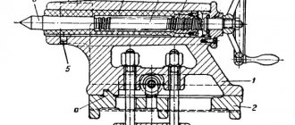
To sharpen a cone on a lathe in this way, you need to install a special device on the machine - a cone or a carbon ruler. The simplest design of a conical ruler is shown in Fig. 2. On the brackets 1, screwed on the back side of the frame, a ruler 2 is fixed, which can be installed at the required inclination angle α to the line of the machine centers. A slider 3 moves along the ruler, connected to the transverse slide of the caliper, previously disconnected from the lower carriage by unscrewing the transverse lead screw.
How to grind by turning the upper slide of the caliper?
For this procedure, you can use the following algorithm of actions:
- you need to take the workpiece and fix it with the spindle and tailstock;
- it is necessary to set the optimal rotation speed of the workpiece for turning it. This parameter depends on the hardness of the metal of the part being turned and the durability of the cutting edge of the cutter. If it is not possible to establish the optimal cutting speed, it is necessary to follow an empirical path - changing the speed from lower spindle speeds to higher ones;
- The first step is rough processing. Using a pass-through cutter, the blank must first be shaped into a cylinder. It is better to process the blank near the cams using a bent cutter;
- At the next stage, the resulting cylindrical workpiece must be given the shape of a cone. To do this, you need to rotate the upper slide of the caliper at an angle equal to half the angle of the cone at the apex.
Using this method, it is possible to produce various cones on the unit in question, without using special complex devices. If the workpiece is made of hard material, then for its processing it is necessary to use high-quality cutters made of carbide metals. These production works must be carried out in compliance with safety regulations.
Cone ruler
Some lathes are equipped with special tapered rulers. Such a device allows you to process external and internal surfaces when the angle of inclination does not exceed 12 degrees. In this case, a cone shape can be made by combining longitudinal and transverse transmission.
When using a ruler, you can select the angle that will be created by simultaneously moving the caliper in the longitudinal and transverse directions. A special ruler allows you to maintain the correct angle throughout.
Processing cones using a cone (copier) ruler
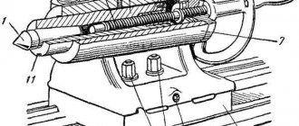
When producing large batches of parts, it is advisable to process conical surfaces using a conical or carbon ruler (Fig. 15). The cone ruler 6 is located on a plate mounted on a bracket at the back of the machine and can be rotated by a certain angle, which is measured on the angular scale 7. The transverse slide 10 is disconnected from its screw and a special rod 2, a nut 3 and a slider 4 are attached to the cone ruler. During longitudinal feed, the transverse slide of the caliper is shifted in the transverse direction under the action of the ruler. The cutter moves at an angle to the axis of the workpiece, making simultaneously longitudinal and transverse movements, and processes the conical surface. The cutter is moved to the required cutting depth by rotating handle 8 of the screw of the upper slide, which is rotated 90° from the normal position.
Fig. 15. Turning of conical surfaces
using a tapered ruler.
ORDER OF PERFORMANCE OF THE Practical Part OF THE WORK.
FORMULATION OF THE REPORT
Each student performs work individually or as part of a team of two or three people. After studying the theoretical part (sections 1-6):
1) Directly on the machine, each team of students studies the controls of the machine and adjusts it (without turning it on) to the minimum, maximum and spindle rotation speeds and feed rates specified by the teacher.
2) In the presence of a teacher (laboratory assistant), the machine is turned on and:
a) turning on the spindle in forward and reverse directions;
b) turning on the caliper feed in all directions;
c) enabling rapid movement of the caliper in all directions;
d) connecting the tailstock and the caliper with a lock and turning on the mechanical movement of the tailstock;
e) turning on the screw feed;
3) Four individual tasks are completed and a report on the work is compiled.
Task No. 1. Write down the main components of the machine.
Task No. 2. Create an equation for the kinematic balance of the main motion chain, ensuring the spindle rotation speed ____ rpm.
Task No. 3. Create an equation for the kinematic balance of the feed chain, providing ____________ feed ____ mm/rev.
Task No. 4. Calculate the settings and adjustments for processing with cutting speed vр=___ m/min and feed Sр=___ mm/rev of the workpiece cone according to Fig. 16.__, having dimensions (mm): D=___, d=___, L=___, l=___.
The student selects specific (numerical) data for tasks No. 2,3,4 from the corresponding columns in the table. 3 according to the option number assigned by the teacher.
| №3 | №4 | |||||
| Option No. | Spindle speed rpm | Feed, mm/rev (transverse, screw-cutting) | The part, its dimensions and design cutting conditions for processing the part | |||
| Sketch - Fig. 16 | D, mm | d, mm | L, mm | l, mm | vр, m/min | Sp, mm/rev |
| Sp=1.04 | A | 0,15 | ||||
| Sp=0.87 | A | 0,2 | ||||
| Sp=0.78 | A | 0,25 | ||||
| 31,5 | Screw=16 | b | 0,3 | |||
| Sp=0.61 | A | 0,35 | ||||
| Sp=0.52 | A | 0,4 | ||||
| Screw=10 | b | 0,15 | ||||
| Sp=0.07 | b | 0,2 | ||||
| Sp=0.075 | A | 0,25 | ||||
| Screw=1 | b | 0,3 | ||||
| Sp=0.085 | b | 0,35 | ||||
| Sp=0.11 | b | 0,4 | ||||
| Screw=5 | A | 0,15 | ||||
| Sp=0.12 | A | 0,2 | ||||
| Sp=0.13 | A | 0,25 | ||||
| Screw=20 | b | 0,3 | ||||
| 630 – zush | Sp=0.195 | b | 0,35 | |||
| 630 - for example | Sp=0.15 | A | 0,4 | |||
| Screw=3 | A | 0,15 | ||||
| Sp=0.15 | b | 0,2 | ||||
| Sp=0.24 | A | 0,25 | ||||
| Screw=24 | b | 0,3 | ||||
| Sp=0.26 | b | 0,35 | ||||
| 12,5 | Sp=0.28 | b | 0,4 |
Explanations for completing the tasks are given below.
B. The report is compiled on separate sheets or in a notebook. At the top of the first sheet is written:
| Tula State University | Student_________________ Group__________ |
| Department of ACC | Date___________ Checked ________________ |
| Laboratory work No. 3 | |
| Setting up and commissioning a screw-cutting lathe model 1K62 |
Next, the text of the task is written down (without the words “Task No.,” “Write,” “Compose,” “Produce”) and its execution. Tasks No. 2-4 are recorded with data from the table. 3. The sketch of the part in task No. 4 is not drawn.
B. Explanations for completing tasks
The kinematic balance equations for tasks No. 2 and No. 3 are written without abbreviations, in full. The actual values of the spindle speed and feed are calculated and recorded in a report.
a specific part (Fig. 16, a or 16, b) for calculating the settings and adjustments for turning a conical surface is indicated by the corresponding letter (a or b) in the first column of task No. 4 of the table. 3.
Rice. 16. Sketches of processed parts
When performing this task, assume that the workpiece has a diameter of D. The processing should be carried out by displacing the tailstock. The procedure for calculating tuning and commissioning is as follows:
a) determine the taper k and the cone slope angle α;
b) determine the amount of displacement H of the tailstock body; indicate in which direction the body should be shifted;
c) choose how the displacement of the tailstock body will be controlled, and make a simplified corresponding sketch;
d) select the required spindle speed, for which:
— determine, based on the given design cutting speed vр, the estimated rotation speed nр: nр=1000 vр /(p×d);
— select the spindle speed nj (j=1-23) closest to nр from the modes provided in the machine. 1K62; should be nj ≤ nр, but nj > nр can be accepted if this excess does not exceed 5-10%;
— write down the equation of the kinematic balance of the main motion chain (without abbreviations), providing the spindle rotation frequency nj and determine the actual value of this frequency n;
— determine the cutting speed v, which will be provided at frequency n:
e) select the longitudinal feed closest to the given calculated Sр from among those provided by the machine; write down the equation of the kinematic balance of the chain (without abbreviations) that provides such a feed and determine the actual value of the feed S. It is imperative to make sure that the required feed is feasible at the selected spindle speed.
4) Answers to test questions are prepared (orally) and the work is defended in front of the teacher.
CONTROL QUESTIONS
1. What work is performed on a screw-cutting lathe?
2. What is the structure of the machine model 1K62?
3. What components does the caliper consist of?
4. What data are accepted as the main parameters of screw-cutting lathes
5. What mechanized movements can be carried out in the machine?
6. What movements can be performed in the machine manually?
7. What cutting tool is used on the machine and where is it installed?
8. In what devices can workpieces be installed on the machine?
9. Which handles turn on the spindle rotation, and which clutch is activated?
10. What is the purpose of the overrunning clutch?
11. What is the purpose of the safety clutch located in the caliper apron?
12. How are the calculated movements of the final links of the main movement chain recorded?
12. How are the calculated movements of the final links of the longitudinal feed chain recorded?
13. What methods of processing conical surfaces on lathes exist, what are their differences?
14. Feeds are switched on using a “mnemonic” handle. How to understand this?
15. What is the setting of the machine?
16. What is the setup of the machine?
17. Is it possible on the machine to simultaneously turn on the screw-cutting feed and the longitudinal feed from the drive shaft?
18. Is it possible on the machine to simultaneously turn on the screw feed and the transverse feed from the running shaft?
19. In what units is the cutting speed set when turning on a machine mod. 1K62?
20. In what units is the feed rate set when turning on a machine mod. 1K62?
| THE WORK IS CONSIDERED COMPLETED AND ACCEPTED BY THE TEACHER after he has reviewed the completed form and received the correct answers to control questions and questions about the procedure for completing the work. |
* It is customary to talk about longitudinal and transverse movement of the caliper
the transverse slide of
the caliper with the parts mounted on them moves in the transverse direction
Setting up the machine for turning a cone
Depending on the specifications, the machine is adjusted to a specific angle. This is done by loosening the fastening nuts. As a rule, the machine already has the necessary notches that will allow you to set the angle quickly and accurately.
After completing the machine setup, the nuts must be tightened again as much as possible. This must be done, since otherwise negative vibrations will occur at the joints, which will complicate the manufacturing process.
If you decide to grind a cone on a factory machine, it is very likely that the caliper will move very reluctantly. This is due to the fact that the wedges are inserted into the stops. Again, a similar solution is used to minimize negative vibrations during machine operation.
Christmas trees made of cardboard
Small tabletop cardboard Christmas trees are an excellent New Year's decor. To strengthen crafts, you can make them by gluing 2-3 layers of cardboard. The work process follows the same principle as with plywood Christmas trees, only instead of a jigsaw or saw we use scissors. We decorate the trees with miniature toys, ribbons, bows, etc.
Wrapping with twine is a simple decoration. You can attach a magnet to the back of the craft.
Christmas trees made of cardboard, covered with burlap. Decorations - beads, lace ribbons, bouquets of artificial flowers. We attach the triangle to a straight branch that will imitate a trunk. We plant a Christmas tree in a pot.
You can cover Christmas trees with fabric of any color
It is important that the decorations contrast with the background
An option for decorating a cardboard Christmas tree is cotton papier mache. It’s simple: we glue layers of cotton wool onto a cardboard base using PVA glue.
Advantages of Morse taper
In addition to the ability to quickly change the tool and firmly secure it in the machine, avoiding displacement and, accordingly, reconfiguration of the machine, the Morse taper provides a number of other advantages.
Firstly, the use of a Morse taper led to a significant reduction in the size of the tool shank without losing the reliability of its fastening in the machine.
Secondly, it provides additional emphasis along the fastening axis with a shorter tool length compared to a cylindrical shank.
Read also: How to make a square from a rectangle?
Thirdly, it significantly reduces the likelihood of the tool jamming in the spindle.
How to make an internal cone on a lathe
How to make an internal cone on a lathe. Help an inexperienced turner! You need to make a copy of the pulley, a seat with a cone. The original is lying on the table and I just can’t figure out how to make the same cone. There are no degree meters, and the degree on the machine will probably not be accurate. Are there any tricks to copy a cone?
How to make an internal cone on a lathe.
I would grind the mating part by lapping along the original hole, and then calmly sharpen the new one by fitting along the machined cone
How to make an internal cone on a lathe.
Zuvs, that's right.
How to make an internal cone on a lathe.
Clamp the sample into the chuck with the cone facing outward. Place an indicator on the small longitudinal lever. Unfold the small longitudinal one and move the indicator back and forth along the inner surface of the cone until you adjust the movement of the small longitudinal one parallel to the generatrix of the original cone. And then sharpen a new cone.
How to make an internal cone on a lathe.
https:///gosts/gost/17554/ this is most likely a standard cone with a taper of 1/10
How to make an internal cone on a lathe. Sorry for ignorance, can anyone give a link or photo of what a lever indicator looks like? The cone fits on the crankshaft of the ud-2 engine. How to make an internal cone on a lathe. How to make an internal cone on a lathe. Here. How to make an internal cone on a lathe.
Got it, I'll have to get one of these!
How to make an internal cone on a lathe.
Ilfat (12 April 2012 — 21:12) wrote:
Got it, I'll have to get one of these!
if the machine has a cone ruler, then I advise you to sharpen along it, and not by turning the upper slide. How to make an internal cone on a lathe.
I heard about the cone ruler, but I didn’t see what it looks like, if it’s not difficult for anyone, please show me a photo.
How to make an internal cone on a lathe. Photo from the Internet.
Attached images
How to make an internal cone on a lathe. Thank you!
How to make an internal cone on a lathe.
Ilfat (12 April 2012 — 19:51) wrote:
measure the length of the cone, the smaller and larger diameter. Draw on paper, calculate the angle. How to make an internal cone on a lathe.
there is a formula d large minus d small (diameters) divided by 2 l, that is, the length of the cone multiplied by 2, we look for the resulting value in the table of tangents ..... there you adjust the resulting angle of the tool holder .... you'll figure out there is, of course, another geometric method, well, I think you'll figure it out
How to make an internal cone on a lathe.
MTZ-80, crankshaft cone dimensions UD-2: D=31.8; d=28; l=32. Taper according to the formula: tg2α=(Dd)/2l=(31.8-28)/64=0.0594. Angle α=1.7o
How to make an internal cone on a lathe. MTZ-80, when manufacturing a part, the fit may be a little tighter along a larger diameter, but not at a smaller one - it is checked by the print. How to make an internal cone on a lathe.
Yugra (10 December 2022 — 20:09) wrote:
crankshaft cone dimensions UD-2: D=31.8; d=28; l=32
Where does the information come from? Tyrnet says that 32.5x28.5x40 This is more like the truth, since the Gostovsky 1:10 turns out. How to make an internal cone on a lathe. MTZ-80, IMHO, don’t bother with a ruler or formulas, it won’t work out better than the indicator, especially since the machine probably isn’t of high accuracy. Be sure to take a magnetic stand for the indicator, or just a kit. like this: I don’t know how you work without it. The most necessary thing! Sharpen with low feed, it will probably wear out less. It will be more accurate. You need to measure strictly at the level of the cutter you will be processing. When measuring, first make sure that the cone does not hit the chuck either at the rear edge or at the front. Good luck.
Post edited by Mixxp: 11 December 2022 — 05:06
How to make an internal cone on a lathe.
Kuvaldych, if we bore the pulley to this size, we rest the hub against the cover bolts. At one time I had to do this kind of work quite often.
Inspection of conical surfaces
The taper of the outer surfaces is measured with a template or a universal inclinometer. For more accurate measurements, bushing gauges are used (Fig. 4.38), with which they check not only the angle of the cone, but also its diameters. Two or three marks are applied to the treated surface of the cone with a pencil, then a sleeve gauge is put on the cone being measured, lightly pressing on it and turning it along the axis. With a correctly executed cone, all marks are erased, and the end of the conical part is located between marks A and B.
When measuring conical holes, a plug gauge is used. The correct machining of a conical hole is determined (as when measuring external cones) by the mutual fit of the surfaces of the part and the plug gauge. If a thin layer of paint applied to a plug gauge is erased at a small diameter, then the cone angle in the part is large, and if at a large diameter, the angle is small.
Christmas trees from pots
The simplest New Year's crafts. You will only need:
- flower pots of different sizes;
- dye;
- small toys for decoration - stars, flowers, etc.
We paint the pots - not necessarily with green paint, because the Christmas tree is decorative. When the paint is dry, glue on the decor. To increase the stability of the Christmas trees, you can insert some kind of pin or thin round stick through the drainage holes in them.
If you don’t want to make anything (or don’t have time for it), we use the pot as a container in which we plant a spruce branch. It will be enough to decorate the top of a small New Year's tree with a star.
Methods for turning a cone, processing shaped surfaces
Cone turningShape turning
Machining of conical surfaces on lathes is carried out in three ways.
First way
The first method is that the tailstock body is shifted in the transverse direction by an amount h (Fig. 15, a). As a result, the axis of the workpiece forms a certain angle a with the axis of the centers, and the cutter, during its movement, grinds the conical surface. From the diagrams it is clear that
h = L sin a; (14)
tgα=(Dd)/2l; (15)
Solving both equations together, we get
h=L((Dd)/2l)cosα. (16)
This method is unsuitable for the manufacture of precise cones due to the incorrect position of the center holes relative to the centers.
Second and third way
The second method (Fig. 15, b) is that the cutting slide is rotated by an angle a, determined by equation (15). Since feeding in this case is usually carried out manually, this method is used when processing cones of short length. The third method is based on the use of special devices that have a copying ruler 1, mounted on the back side of the frame on brackets 2 (Fig. 15, c). It can be installed at the required angle to the center line. A slider 3 slides along the ruler, connected through a pin 4 and a bracket 5 with a transverse carriage 6 of the caliper. The carriage cross feed screw is separated from the nut. When the entire support is moved longitudinally, the slider 3 will move along the fixed ruler 1, communicating one
Rice. 15. Schemes for processing conical surfaces
temporary transverse displacement of carriage 6 of the caliper. As a result of two movements, the cutter forms a conical surface, the taper of which will depend on the angle of installation of the copy ruler, determined by equation (15). This method provides accurate cones of any length.
Processing of shaped surfaces
If in the previous copying device a shaped ruler is installed instead of a conical ruler, the cutter will move along a curved path, processing the shaped surface. For processing shaped and stepped shafts, lathes are sometimes equipped with hydraulic copy supports, which are most often located on the rear side of the machine support. The lower slide of the support has special guides, usually located at an angle of 45° to the axis of the machine spindle, in which the copying support moves. In Fig. 6, b showed a schematic diagram explaining the operation of the hydraulic copying support. Oil from pump 10 enters the cylinder, rigidly connected to the longitudinal support 5, on which there is a transverse support 2. The latter is connected to the cylinder rod. Oil from the lower cavity of the cylinder, through the slot 7 located in the piston, enters the upper cavity of the cylinder, and then into the follower spool 9 and to the drain. The follower spool is structurally connected to the caliper. Probe 4 of spool 9 is pressed against copier 3 (in area ab) using a spring (not shown in the diagram).
In this position of the dipstick, oil flows through spool 9 to the drain, and transverse support 2, due to the difference in pressure in the lower and upper cavities, moves back. At the moment when the probe is in area be, it is recessed under the action of the copier, overcoming the resistance of the spring. In this case, the oil drain from spool 9 is gradually blocked. Since the cross-sectional area of the piston in the lower cavity is larger than in the upper cavity, oil pressure will force caliper 2 to move down. In practice, there are a variety of models of lathes and screw-cutting lathes, from tabletop to heavy-duty ones, with a wide range of sizes. The largest processing diameter on Soviet machines ranges from 85 to 5000 mm with a workpiece length from 125 to 24,000 mm.
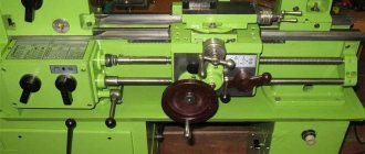
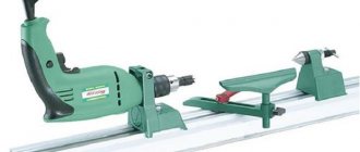
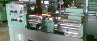
Subtleties of choice
If working with wood is just a pleasant hobby and you don’t have a whole workshop with a full arsenal of all the tools at your disposal, then the choice of machine is critically important.
There are a number of parameters, paying attention to which will reduce the likelihood of an unsuccessful choice significantly
What to look for when choosing
Most often, very compact devices, tabletop lathes, are purchased to satisfy the creative itch. Of course, in terms of accuracy and engine power, they cannot be compared with powerful industrial analogues, but the price of such devices is reasonable.
When choosing, you should pay attention to such machine parameters as:
maximum permissible dimensions of the workpiece being processed. The documentation for the machine must indicate the turning diameter (the maximum size of the workpiece in the transverse direction) and the length of the bed (the maximum permissible length of the workpiece);
A compact lathe will not be able to process a long workpiece
- power - roughly speaking, the more powerful the device, the better, but with increasing power, the dimensions of the machine also increase. So you need to find a middle ground;
- the material from which the bed is made, as well as the material of the frame. From the point of view of stability, models with a steel frame and a cast iron frame can be considered optimal. True, the weight of such machines is quite large, so if you plan to frequently relocate it, then it is better to choose a lighter model;
Basic elements of an industrial machine
As for the device, the key elements of a lathe include:
- cutter holder – allows you to securely fix the cutter and move it in 2 directions during operation (along the workpiece and in the transverse direction);
- headstock - in conventional machines it is located on the left (if the turner is right-handed). It consists of elements such as a drive mechanism and a spindle, the center of which rotates during operation, causing the workpiece to rotate.
Read also: Antenna circuits for television reception
From left to right: headstock, tool holder, tailstock
What kind of cutters will you need?
Even in order to make such a simple element as turned legs for a wooden table, you will need several different types of cutters.
It is advisable that an amateur turner have in his arsenal:
semicircular cutters - they will be needed for rough processing, for example, in order to turn a workpiece in the form of a parallelepiped into a cylindrical one. Also, semicircular cutters can be used for finishing, small-width cutters (no more than 20 mm) can be used to create decorative grooves in the workpiece, and wide models (up to 50 mm) are used for processing large concave surfaces;
Cutting part shape
- a flat cutter can be used for chamfering and processing curves. The cutting part has a 2-sided sharpening and forms an angle of up to 70ᵒ with the side edge;
- to process internal surfaces (such products as turned wooden vases cannot be made without this), you will need shaped cutters;
- hook-shaped cutters can also be used.
If a suitable cutter is not at hand, you can always make it yourself from an old file or an ordinary wood chisel. An error of a couple of degrees when sharpening will not seriously affect the result of the work.
Sometimes you have to manually modify purchased cutters. For example, when it is necessary to make a slot in a workpiece, when using a conventional cutter, the side internal parts are quite rough. This can be fixed quite simply - just sharpen the sides of the cutter.
Shortened Morse tapers
In the process of development of machine tool building, machines appeared in which the dimensions of the tool chucks turned out to be smaller than the length of standard Morse tapers, which created great problems with selecting a tool and installing it in the machine. For such machines, a separate type of shortened Morse tapers was developed.
The main feature of such cones is that while maintaining a larger diameter and taper, the length of the shank has been reduced. At the same time, shortened cones, thanks to maintaining their shape, are in no way inferior to standard ones. They allow you to securely fasten the tool and just as quickly replace it.
Types of cones
Morse can be manufactured using different technologies, so it is not always possible to replace one tool with another without problems.
Before selecting a suitable fairing, you need to decide what dimensions the Morse cone has that correspond to GOST .
Tools often differ from each other in length, diameter, and angle.
When choosing a fairing, you need to pay attention to the letters and numbers:
- the number opposite the letter “D” means the basic size of the cone socket;
- the number next to “L” is the penetration depth.
These sizes are common to all countries where the metric number system is actively used. Morse fairings created today, as a rule, have adapters that can be changed. This simplifies the work, since the equipment can be combined with different standards.
Capital letters of the Latin alphabet indicate features of the flange section. The proluvium itself can have a length from 2.5 cm to 16 cm.
Today, the highest quality fairings for drilling machines can be considered tools that are produced under the brands “Kennametal” and “Kapto”.
Those who work on the machine know very well that they have good resistance to sudden and significant changes in temperature. The cones of these brands are quite durable and easy to use. They meet all the necessary requirements. Morse codes, which are marked "Capto", are released and distributed throughout the world.
Today, such instruments are promoted as high-end analogues of HSK. The fairing itself, when projected onto a plane, will have the shape of a triangle. There are indentations on its round edges. But it should be noted that such a tool has a rather high price, since its manufacturing process is very complex. In turn, Kapto are divided into several types , the most popular among which are those designated as “C3” and “C10”.
Initially, such a tool was created so that it could be used for clamping using the collet method.
There is a division into 8 sizes: the smallest of them is designated as “KM0”, and the largest is designated as “KM7”. All other types of cones are also designated by the letters “K”, “M” and a number from 1 to 6
. However, the Russian standard does not recommend using the KM7 Morse fairing; instead, a metric cone No. 80 is used.
Fairings that are designed to both inch and metric standards can be interchanged. They are similar in every way and differ only in the thread of the shank.
Designation of taper in the drawing
When creating technical documentation, all established standards must be taken into account, otherwise it cannot be used in the future
When considering the taper designation in the drawings, attention should be paid to the following points:
- The diameter of the large base is displayed. The figure under consideration is formed by a body of rotation, which is characterized by a diametrical indicator. In the case of a cone, there may be several of them, and the change in the indicator occurs smoothly, not stepwise. As a rule, such a figure has a larger diameter, as well as an intermediate one if there is a step.
- The diameter of the smaller base is applied. The smaller base is responsible for forming the required angle.
- The length of the cone is calculated. The distance between the smaller and larger bases is an indicator of length.
- Based on the constructed image, the angle is determined. As a rule, appropriate calculations are carried out for this. In the case of determining the size from a printed image, using a special measuring device, the accuracy is significantly reduced. The second method is used when creating a drawing for the production of non-critical parts.
The simplest designation of taper also provides for displaying additional dimensions, for example, reference. In some cases, a taper sign is used, which makes it immediately clear about the difference in diameters.
There are quite a large number of different standards that relate to the designation of taper. The features include the following:
- The angle can be specified in degrees as a fraction or as a percentage. The choice is made depending on the area of application of the drawing. An example is that in the mechanical engineering field the value of a degree is indicated.
- In the mechanical engineering field, the concept of normal taper is included in a special group. It varies within a certain range and can be 30, 45, 60, 75, 90, 120°. Similar indicators are characteristic of most products that are used in the assembly of various mechanisms. At the same time, it is much easier to maintain such values when using turning equipment. However, if necessary, inaccurate angles can be maintained, it all depends on the specific case.
- When drawing the main dimensions, a drawing font is used. It is characterized by quite a large number of features that must be taken into account. Tabular information is used for correct display.
- To begin with, the taper icon is indicated from which the arrow is drawn and the value is displayed. The display features largely depend on what kind of drawing. In some cases, a large number of different sizes are applied, making taper application much more difficult. That is why it is possible to use several different methods for displaying such information.
In the drawing, the indicator in question is indicated in the form of a triangle. This requires a digital value that can be calculated using various formulas.
Read also: Not an integral part of a metal plane
Formula for determining taper
You can independently calculate the taper by using various formulas. It is worth considering that in most cases the indicator is indicated in degrees, but it can also be expressed as a percentage - it all depends on the specific case. The calculation algorithm is as follows:
- K=Dd/l=2tgf=2i. This formula is characterized by the fact that the taper is characterized by a double slope. It is based on obtaining the value of the major and minor diameters, as well as the distance between them. In addition, the angle is determined.
- Tgf=D/2L. In this case, the length of the segment that connects the large and small diameters, as well as the indicator of the large diameter, is required.
- F=arctgf. This formula is used to convert the indicator to degrees. Today, in most cases, degrees are used, since they are easier to maintain when directly carrying out constructions. As for percentages, they are often indicated to enable the calculation of one of the diameters. For example, if the ratio is 20% and a smaller diameter is given, then you can quickly calculate the larger one.
As previously noted, the 1:5 taper and other indicators are standardized. For this, GOST 8593-81 is used.
Calculations are not shown in the drawing. As a rule, an additional explanatory note is created for this purpose. It is quite simple to calculate the basic parameters; in some cases, a drawing is constructed, after which the angle value and other indicators are measured.
Taper value
When considering taper, it should be taken into account that this indicator is directly related to the slope. This parameter determines the deviation of a straight line from a vertical or horizontal position. However, a 1:3 taper or a 1:16 taper is significantly different. The definition of slope is characterized by the following features:
- Slope refers to the ratio of the opposite side of a right triangle to the adjacent side. This parameter is also called the tangent of the angle.
- The following formula is used for calculation: i=AC/AB=tga.
This indicator can be calculated in a variety of ways; the most widely used formula is K=D/h. In some cases, the designation is carried out as a percentage, since this variable indicator is used to determine all other parameters.
Using a wide angle cutter
A fairly simple way to obtain a tapered surface on a lathe is to use a corner cutter. With its help, you can create a cone of short length; the cutting edge should be straight. The angle of the taper can be adjusted by sharpening the edge or setting it at a specific angle to the workpiece.
Turning a cone with a cutter
All of the above methods require certain skills in operating a lathe. In some cases, for large-scale production, special copiers are made. For small-scale production, a method that uses a ruler or turning the lathe slide or shifting the headstock is suitable.
How to sharpen using the method of displacement relative to the axis of centers?
This method allows turning only external conical surfaces on a turning unit. In the process of making a cone using this technique, a misalignment of the center holes occurs. This method does not have the particular precision with which a conical surface can be created.
Important!
This method allows the use of mechanical caliper feed, which makes it possible to use simple types of units. The off-axis method makes it possible to create a long Morse cone.