A wood lathe is a valuable piece of equipment for any woodworker. It doesn’t matter whether the unit is used in a workshop or solely for minor work in a home workshop, sometimes parts fail and require replacement.
Many of the parts of a wood lathe can be made at home with your own hands. This will be more economical and practical than purchasing an industrially produced structural element.
Functional features and device
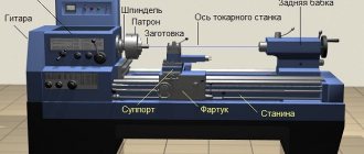
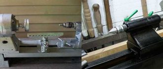
The tailstock and headstock of any lathe are important structural parts, each of which performs its own functions.
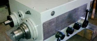
Headstock. The quality of the entire structure as a result depends on the precision of manufacturing of this part. A spindle is located on the headstock, which transmits torsional movement to the workpiece. The main elements of the headstock are:
- frame;
- spindle;
- bearings;
- design for controlling the direction of spindle movement;
- a device that controls the speed of the spindle;
- device for connecting and installing equipment.
Tailstock. This is the support unit of a woodworking lathe, which is designed to fix the workpiece. Main elements of the tailstock design:
- frame;
- quill;
- flywheel;
- flywheel handle;
- screw to move the tailstock laterally.
The tailstock has a hole in the quill into which a tool is inserted to process the part. During the working process, the headstock moves along the bed to select the optimal distance depending on the length of the workpiece being processed.
History of lathes in the Soviet Union
The development of machine tool industry in the USSR began after the October Revolution. After the discovery of high-speed steel and hard alloys, powerful units began to be produced. 1A62 is one of the first machines that began to be used in mass and serial production. Released.
In 1956, it was replaced by an improved modification 1K62 with greater power and a range of modes. Later, engineers continued to work on improving the design of the units. To this day, enterprises operate 16K20, DIP 200, DIP 300 and other models.
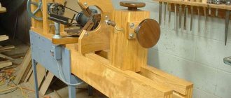
Step-by-step assembly and installation yourself
After studying the diagrams and drawings, you can proceed to the assembly and installation of both components of the lathe. Then you will need to set up and configure the equipment.
Headstock
Algorithm for making the headstock:
- Turn out a cylindrical body with a wall thickness of 10 mm.
- The channel, which will be necessary to make a drain for attaching the headstock to the frame, is welded to a corner of sheet steel.
- Attach the headstock to the stand.
The cylindrical body has the following dimensions:
- outer diameter – 56 mm;
- length – 18 cm;
- mounting sockets with a diameter of 24 mm for bearings;
- shaft diameter – 30 mm.
Tailstock
Tailstock manufacturing algorithm:
- weld 2 bolts together to increase the overall length;
- make a rotating center from a pipe of such diameter that the outer race of the bearings fits tightly into it;
- If necessary, you can make a 2-3 mm wide cut in the resulting sleeve;
- the future wall of the rotating center has the same diameter as the outer race of the bearing;
- scald the washer and nut on the right side;
- Tighten the left nut and cut the horses flush with the washer;
- cut off the head of the bolts, clamp the bolt itself into a drilling machine and refine it using an abrasive stone.
Then you need to make the spindle housing. For this:
- Take a piece of pipe with a diameter of ¾ inches, 6-7 cm long.
- Nuts are welded at both ends.
- The tailstock cone is also made from a bolt.
Before installation, first grind the cone shank to such an extent that it fits into the inner race of the bearings. To support the outer race, before installing the bearings, install a ring of bent wire with a diameter of 1-2 mm into the housing.
Methods for brazing carbide inserts
Soldering of carbide plates is carried out in flame, gas or electric muffle furnaces Source youtube.com
Soldering of cutters consists of heating the plate itself and melting the solder, which can be done in different ways using:
- High frequency currents.
- Plasma gas or muffle furnaces.
- Contact welding.
- Oxy-acetylene torch.
Recommendation: for silver solders, high-titanium alloys T60K6 or T30K4 should be used, which reduce the thermal stress that appears during cooling.
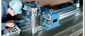
First start-up and equipment health check
To check the serviceability of the equipment, you must first run the machine at idle speed. Each master configures the machine in his own way, depending on the intended work and functions performed. All elements must be checked sequentially; only after checking at idle speed can you turn off the machine and set certain parameters for operation.
Before processing the workpiece, be sure to make sure that the wood is free of chips, deformations and cracks. The spindle should rotate without the slightest difficulty during operation. Be sure to check the coincidence of the centers of symmetry of the machine and the part.
Video description
Soldering a turning tool.
In flame, gas or muffle furnaces
First of all, the holder head is heated in an oven to a temperature of 800°C, at which the borax melts (Na₂[B₄O₅(OH)₄]·8H₂O). Then powdered or paste-like borax is poured onto the seat and sent back to the oven. The newly heated part is taken out of the furnace and, using a metal brush, the slag is removed from the place where the cutter fits. After cleaning, the seat is again sprinkled or smeared with flux, a carbide plate is placed there, it and the seat base are thickly sprinkled with brown, solder is placed on top and again sent to the oven, heated to 1200°C until the solder melts.
After the solder has melted, the cutter is removed from the oven, placed on some flat metal surface and, if necessary, the carbide plastic is adjusted. Then the plate is pressed tightly to the seat (you can use a minus screwdriver) and wait 5-6 seconds until the solder sets. But all this needs to be done very quickly, before the part has cooled down.
To avoid cracking of the solder from thermal stress during cooling, the finished cutter is immersed in a box with heated sand or ground charcoal. Of course, if you have a chamber oven at home, then heat it to 250°C, place the cutter there and leave it until it cools completely along with the oven. After all the procedures, the cutter is cleaned in the factory with a sandblaster, but at home you can do this with a metal brush.
Electric drive of the jointer
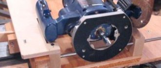
And of course, don’t forget about the drive. All mechanisms must rotate. This means that the drive will be the “heart” of the machine. Here are some recommendations for this design element: - first of all, prepare the electric motor.
Electric motor for jointer
It is best to use a three-phase unit for these purposes. Of course, in this case you may have to redo the electrical network in your workshop, but it will be worth it. Three-phase electric motors operating at a voltage of 380 V are capable of developing greater power. In addition, the torque of such devices is suitable for our purposes. The minimum power value should be 3 kW, but the maximum is at your discretion;
- To transmit torque from the electric motor to the working shaft, it must be done using belts. A two-strand wedge-shaped shape is best suited for these purposes. Such belts are more reliable;
- the electric motor itself can be mounted cantilever, directly inside the machine frame. This method will help solve the problem associated with belt tension. If you want to strengthen the engine more firmly, then you need to add a slide to the design, with the help of which adjustments will be made;
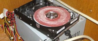
- to increase the shaft rotation speed, it is worth using two pulleys. One, larger in diameter, is installed on the electric motor. A pulley with a smaller cross-section is mounted on the shaft.
Be very careful about providing power to the machine. Three-phase current is supplied through a four-core cable. In this case, reliable grounding must be organized. These requirements will help avoid accidents when working on the machine.
Location of controls for drilling machine 2A112
Location of controls for drilling machine 2a112
Specification of machine controls 2A112
- Spindle manual feed handle
- Handle for fixing the spindle head on the column
- Handle for moving the spindle head along the column
- Motor control buttons
- Nut for adjusting spindle speed
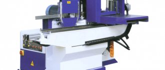
Why do you need a jointer?
A woodworking shop can have a variety of machines, but the most commonly used (besides the circular saw, of course) are jointers and planers. These two types of units are slightly similar in their function, but differ in the method of use.
If you need to make a wooden blank in the form of a board, beam or shield, then it is better to use a thickness planer. Such a device, the main tool of which is the same knife, is capable of cutting the source material into two parallel parts. In this case, both of them will be adjusted to certain sizes.
Thicknessing machines are available in both single-sided and double-sided types. In the first case, only one side of the workpiece is processed in one pass. A double-sided thickness planer is more productive. Here the output is an almost finished part.
Thicknessing machines have a shaft located above the tabletop. Moreover, the latter is made massive in order to smooth out large vibrations. In addition, the mechanism is equipped with a special casing, which is designed to dampen noise.
A jointer has a slightly different task. This device is used to create a smooth surface without significant roughness on the workpiece. This machine, like the previous version, is equipped with a shaft with knives, only in the jointer it is located under the table top.
The workpiece is fed onto the work surface from one side, and the output from the opposite side is already partially processed. This way, layer by layer, the desired evenness is achieved. After processing on a jointer, the part can be fed to a surface planer.
Main technical characteristics of the T-65 machine
| Parameter name | T-65 | S-95 | T-28 |
| Basic machine parameters | |||
| Accuracy class | N | N | N |
| The largest diameter of the workpiece above the bed, mm | 120 | 50 | 130 |
| The largest diameter of the workpiece above the support, mm | 30 | 12 | 14 |
| Height of centers above flat bed guides, mm | 65 | 32 | 65 |
| Maximum length of the workpiece at centers (RMC), mm | 200 | 125 | 220 |
| Maximum turning length, mm | 70 | 55 | |
| Maximum height of the cutter holder, mm | 7 x 7 | 6 x 9 | 8 x 8 |
| Height from the cutting surface to the center line, mm | 6 | 6 | 6 |
| The greatest distance from the axis of the centers to the edge of the tool holder, mm | 50 | ||
| Spindle | |||
| Diameter of through hole in spindle, mm | 10 | 8 | 10 |
| Morse taper spindle | № 1 | 39°30` | № 0 |
| Number of speed steps for direct spindle rotation | 3 | 3 | 3 |
| Spindle direct rotation frequency, rpm | 77, 66, 55 | 1300..3000 | 1440, 2500, 4300 |
| Caliper. Submissions | |||
| Maximum lateral movement of the caliper, mm | 70 | 44 | 55 |
| Transverse movement of the caliper by one division of the dial, mm | 0,05 | 0,01 | 0,01 |
| Maximum movement of the cutting slide, mm | 70 | 38 | 55 |
| Movement of the cutting slide by one division of the dial, mm | 0,05 | 0,01 | 0,01 |
| Angle of rotation of the cutting slide, degrees | ±90° | ±90° | ±60° |
| Tailstock | |||
| Tailstock cone | Morse No. 1 | 39°30` | Morse No. 0 |
| Maximum movement of the quill, mm | 45 | 30 | 45 |
| Electrical equipment | |||
| Main drive electric motor, kW | 0.25 1400 rpm | 0.15 2700 rpm | 0.27 2800 rpm |
| Dimensions and weight of the machine | |||
| Machine dimensions (length width height), mm | 675 x 300 x 250 | 420 x 200 x 250 | 650 x 255 x 222 |
| Machine weight, kg | 19 | 19,2 | 25 |