Repair of lathe bed guides
During a major overhaul of a lathe, the accuracy of the bed guides is restored. When choosing a restoration method, they are guided by the degree of wear. When the error does not exceed 0.15 mm over a length of 1000 mm, they are restored by scraping. With greater wear, they resort to mechanical treatment: grinding or planing. When the guides are hardened, the main method of repair is grinding.
Repair by scraping
Scraping of guides or scraping followed by lapping remains the most effective way to restore their geometric and technical accuracy. And now this method is often used, demonstrating excellent results in machine bed repair for many decades. First of all, it is necessary to examine the condition of the guides and determine the degree of their wear. The place where the wear is minimal is taken as the base level, and the measurement data is entered into a table, on the basis of which repairs will be made. In a lathe, the base surface is most often taken to be the location of the tailstock, which practically does not wear out during operation of the equipment. The method includes the following steps:
Since the guides of the lathe bed are quite long, processing is carried out along the beacons, dividing the total length into sections. The first beacon is always the place of maximum production. At a distance less than the length of the straight edge from the first beacon, a second beacon is scraped, located in the same plane as the first. Then the entire surface between the beacons is scraped, followed by moving to the adjacent area. Periodically, apply a ruler with paint to assess the condition of the guides and the quality of work.
Watch the video of rough scraping
Non-hardened parts of lathe guides are subjected to this treatment; the method guarantees the achievement of high surface accuracy (0.002 mm per 1000 mm length). The tiny holes formed after scraping are able to hold the lubricant well and distribute it evenly. The quality of scraping depends entirely on the professionalism of the worker.
Installing the Lead Screw and Lead Shaft
This operation is excluded if the carriage repair is performed according to table. 5.
The alignment of the axes of the lead screw and the lead shaft, the feed box and the apron is carried out in accordance with the following standard technological process.
1. Install the feed box housing and secure it to the frame with screws and pins.
2. Install the carriage in the middle part of the frame and attach the rear clamping bar of the carriage with screws.
3. Install the apron and connect it to the carriage with screws (the apron may not be installed fully assembled).
4. in the holes of the feed box and apron for the lead screw or lead shaft. The ends of the mandrel must protrude by 100-200 mm and have the same diameter of the protruding part with a deviation of no more than 0.01 mm (play of the mandrels in the holes is unacceptable).
5. Move the carriage with the apron to the feed box until the ends of the mandrels touch and measure the amount of their misalignment (in the light) using a ruler and a feeler gauge.
6. Restore the alignment of the holes for the lead screw and the lead shaft in the feed box and apron by installing new linings, scraping the guides or carriage linings, and reinstalling the feed box.
Permissible deviation from the alignment of the feed box and apron holes: in the vertical plane - no more than 0.15 mm (the axis of the apron hole can only be higher than the feed box hole), in the horizontal plane - no more than 0.07 mm.
Reinstallation of the box height should be done when repairing carriage guides without compensating pads. In this case, the holes in the feed box for the screws securing it to the frame are milled. When moving the box horizontally, it is necessary to mill holes in the carriage for the apron fastening screws: the latter must also be shifted and then pinned again.
Scraping lathe guides
Restoring the geometry of lathe guides
Grinding the bed guides of a screw-cutting lathe
Grinding the bed guides of a screw-cutting lathe
Restoring a lathe bed
Repair by grinding
It is not always possible to use planing or longitudinal milling machines for repairs due to the long length of the lathe bed. In this case, the bed guides are restored using a portable device with a grinding head, which is installed directly on the equipment bed.
Repairs can be made on site, without removing the machine from the foundation. This method ensures high repair accuracy, low surface roughness, and is also indispensable when processing hardened surfaces. This method is many times more productive than scraping, but experts still prefer finishing planing.
Repair by planing
This method is less tedious than scraping and less expensive sanding. For example, the average repair time for machine guides is:
If wear is more than 0.15 mm, manual scraping is replaced by mechanical processing on a longitudinal planing machine with a centralized method of organizing repairs in a repair shop or at a specialized enterprise. The reason is simple: you will have to remove the frame from the foundation and install and align it on the rigid table of the planing machine.
Planing bed guides
At the first stage, test planing is carried out once to obtain a base surface, which will make it possible to determine deviations along the entire length of the bed. To do this, alternately bring the cutter to the most worn surfaces and remove the metal layer until the wear is eliminated. Finish planing is performed in at least two finishing passes with wide carbide cutters. The last pass is performed with a cutting depth of less than 0.05 mm, constantly wetting the cutter and the surface of the guides with kerosene. When wear exceeds 0.4-0.5 mm, the guides are subjected to rough and fine planing. The main disadvantage of this repair method is the considerable time it takes to dismantle the bed, transport, install the bed on the planer table, align and remove the restored bed.
When cutting the flat prismatic surface of the guides, small metal particles of various sizes and shapes are torn out from the solid frame. Furrows and grooves appear on the surface, forming a rough surface. Therefore, sometimes after machining it is impossible to do without scraping or vibration rolling. This increases the strength of the guides due to plastic deformation (changes in the structure of the material). Vibration rolling achieves smoothing of micro-roughness and irregularities by translational movement along and across the axis with specially treated balls or rollers.
Repairing lathe guides using one of the described methods is an element of complex work related to restoring the full functionality and accuracy of metal-cutting equipment. But we should not forget that the quality of the repair, with a minimum period of time for its completion, significantly depends on the degree of preparation of the machine for repair and the qualifications of the mechanic.
Source
Lathe bed. Preparation for repair
The quality of a major or medium repair with a minimum completion time depends on the degree of preparation of the machine for repair and the correct organization of the work of a team of mechanics.
Before stopping the machine for repair, its operation is checked at idle speed in order to identify increased noise and vibration at each stage of spindle speed, and the sample is also processed to determine the condition of the spindle rolling bearings. Check the radial and axial runout of the spindle. These checks are mandatory, since this makes it easier to identify defects, which in some cases are very difficult to identify with a disassembled machine.
The results of the checks are taken into account when compiling a list of defects and repairing the machine.
It is not advisable to carry out other tests of the machine for accuracy in accordance with GOST 42-56 (recommended in some literary sources), since the accuracy of the machine assembly is ensured at all stages of the repair process.
This chapter discusses several variants of technological processes that are used for major or medium repairs of body (basic) parts and assemblies of most models of screw-cutting lathes, for example, 1K62, 1601, 1610, 1613D or 250, 1612V, 1615A, TV-320, 1A616, 1E61, etc. correspond to the modern level of repair production and can be used by repair bases with different levels of equipment.
Questionnaire with price list for grinding lathe 1M63 (RMC 1500, 3000)
Mandatory conditions for grinding: The machine must be disassembled into separate units that are ground and all units must be clean.
1. Grinding of the frame of the RMC series up to 1500 mm. ————————————————55000 rub.
up to 3000 mm —————————————————-80,000 rub.
2.Carriage:
a) grinding of guides ————————————————————————22500 RUR.
b) sticker of linings taking into account zedex ———————————————————12000 rub.
c) grinding (scraping) after sticker ——————————————————12,000 rub.
d) grinding and adjustment of carriage clamps - —————— ——————————6000 rub.
3. Wedge (based on 1 piece):
a) grinding ———————————————————————————————-2250 rub.
b) sticker of linings———————————————————————————-3750 rub.
c) grinding (scraping) after gluing the linings ————— ————————3000 rub.
4. Transverse caliper slide ————————————— ————————7500 rub.
Rotating part of the caliper ————————————————————————9000 rub.
Cutting slide ————————————————————————————9000 rub.
5. Tailstock (grinding the sole and midsole ———————RUB 10,500.
Additional services for the machine
1. Disassembly of the machine into components without subsequent assembly—————————————22,500 rub.
2. Disassembly of the machine components (provided that the machine arrived disassembled into components):
a) carriage assemblies—————————————————————————————12000 RUR.
b) cutting sled————————————————————————————10500 rub.
c) tailstock——————————————————————————————8000 rub.
3. Washing the machine (bed, carriage assembly, cutting slide) ————————-25,500 rub.
4. Washing units:
a) bed————————— ————————————————————————13500 rub.
b) carriage assembly—————————————————————————————9000 rub.
c) cutting sled————————————————————————————3000 rub.
d) tailstock——————————————————————————————3000 rub.
All prices are excluding VAT
Repair of lathe bed guides
Bed guides are restored during repairs in various ways, for example by planing, milling, grinding, broaching, scraping. At some factories, surface hardening of the bed guides is carried out by rolling with a roller, as well as by hardening the solid. hours, which significantly increases the wear resistance of surfaces.
The choice of repair method depends on the degree of wear and hardness of the frame guides, the equipment of the repair base with special machines and devices, etc.
The most common methods for repairing bed guides are scraping, sanding and planing.
Repairing guides by scraping, even with wear of 0.05 mm, is very labor-intensive and expensive, so this process should be mechanized, and this has a great economic effect.
Repairing guides by grinding ensures high accuracy and cleanliness of processing; this method is practically indispensable when repairing hardened guide frames. Labor productivity during grinding is several times higher compared to scraping. However, when repairing unhardened machine guides, preference should be given to finishing planing. At the same time, high productivity is achieved, V6 surface cleanliness and accuracy are ensured in accordance with specifications.
Repair of bed guides by scraping
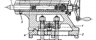
Rice. 48. Aligning the bed of a screw-cutting lathe on a stand
This technological process is characterized by the fact that the bed (installed on a stand or on a rigid foundation) is aligned in the transverse direction along the surface for attaching the feed box 13 (Fig. 48) using the frame level 11. This makes it possible to easily determine and install the caliper during repair perpendicularity of the surfaces for attaching the apron on the caliper carriage to the surface for attaching the feed box to the frame.
The horizontality of the guides in the longitudinal direction is determined in the usual way according to level 10.
Another feature of the typical technological process under consideration is that instead of the wearing surfaces of the guides under the tailstock (on the bed), usually taken as the base, in this case the surfaces for fastening the gear rack are taken as the base, and only sections (200-300 mm each) these surfaces at both ends of the bed. These surfaces never wear out and are in the same plane as the surfaces for attaching the feed box and the drive shaft bracket. Restoring the parallelism of the bed guides to the specified surfaces reduces the complexity of aligning the parallelism of the axes of the lead screw and the lead shaft to the bed guides.
Repair of guide frames using this technology, introduced in the LOMO repair service, comes down to the following operations:
1. Install the frame on a stand or a rigid foundation at a level using wedges and shoes. In the longitudinal direction, the check must be carried out at level 10 (Fig. 48), in the transverse direction - at the frame level applied to plane 13.
The curvature of the guides is checked at level 4, installed on the universal device 3, moved along the guides, or on the tailstock bridge.
Deviations from horizontality of the guides in the longitudinal direction are allowed no more than 0.02 mm over a length of 1000 mm.
The curvature of the guides is allowed no more than 0.02–0.04 mm over a length of 1000 mm.
Rice. 49. Profile of the guides of the bed of a screw-cutting lathe 1k62
Plane 9 (Fig. 49) for attaching the feed box must be located vertically. A deviation of no more than 0.04-0.05 mm over a length of 1000 mm is allowed.
2. Scrape surfaces 3, 4 and 5 along a straight edge for paint. During the scraping process, the curvature of these guides and the parallelism of their surfaces 9 and 10 are periodically checked using a device, level and indicator (check method - see Fig. 10, b).
Non-straightness (towards convexity) is allowed no more than 0.02 mm over a length of 1000 mm. Curvature - no more than 0.02 mm per 1000 mm. Non-parallelism 1 to the base surfaces - no more than 0.06 mm along the length of the guides. The number of paint prints is at least 10 on an area of 25x25 mm.
3. Scrape guides 1, 2 and 6 along a straight edge for paint. Periodically check the parallelism of their surfaces 3, 4 and 5, the deviation of which should be no more than 0.02 mm at a length of 1000 mm and no more than 0.05 mm at a length of 3000 mm.
Spiral tortuosity is allowed no more than 0.02 mm over a length of 1000 mm. The number of paint prints must be at least 10 on an area of 25 x 25 mm.
4. Scrape surfaces 7 and 11 using a straight edge for paint. Periodically check the parallelism of their surfaces 1, 2 and 6 using a device with an indicator. Non-parallelism of no more than 0.02 mm along the length of the guides is allowed.
The final adjustment of surfaces 7 and 11 is made along the caliper carriage along with the clamping strips.
Repair of bed guides by grinding
This technological process consists of the following operations:
1. File and clean all protruding nicks and burrs on the surface 8 of the frame (Fig. 49).
2. Install the frame on the table of the longitudinal planing machine with surface 8, while placing 0.1 mm thick foil under the outer four corners between the supporting planes of the frame and the table surface. The frame is secured at the internal corners (shown by arrows in Fig. 50) and it is verified to be parallel to the movement of the table along surfaces 10 and 9 (Fig. 49) with an accuracy of 0.05 mm over the entire length of the surface.
Explain, I can’t understand how the beds are polished?
And what did you use to lift the raft? Textolite? Bronze? I myself tried to lift the raft and the nut with the coupling. I can’t say that it’s easier; every method has +/-.
Each option has its negative pros and cons (C) :db:
They raised it differently if we are talking about the carriage . Textolite is not good, it rubs the frame and the coefficient. friction is not small, fluoroplastic is very good. good, but every time I'm afraid it will fall off. Although so far it works fine on all the machines we have made. They made brass fittings - good, but scraping will kill you.
We settled on an epoxy-graphite compound.
The technology is like this. We disassemble the carriage completely, turn it over, wash it with a grinder, roughly tear down the sliding surfaces, you can also drill them, if you’re not too lazy (for better grip). We seal these places with masking tape so as not to stain them. Instead of strips that are held in place by felt seals or rubber scrapers, we install plates with nuts welded so that the axis of the hole. was perpendicular to the sliding surface. We screw the installation bolts with locknuts into these nuts. Accordingly, you need 6 installation screws (if one guide is flat and the other is a prism). If both guides are prisms (1M63, 1M65, etc.), then 8 screws.
We turn the carriage over to its natural position, put it in place, set the height, perpendicular and other geometry with screws, fix it with locknuts, double-check the geometry, if OK, move on. When adjusting, make sure that all screws have as even a load as possible.
We turn the carriage over again. Apply liquid oil (thinly) to the bed, in the place where the carriage (with spare parts) will rest on it, and stick on stretch film or film for wrapping products (the same thing).
Prepare the copound (mix).
They are branded from Loctite or there are other manufacturers. We were disturbing our own shit. If you do it with epoxy, beware of its self-heating when mixing - it can instantly harden and also burn. It is best to stir in a thick-walled or water-cooled metal container. They mixed it, removed the masking tape, smeared it thickly and generously on the carriage, turned it over, plopped it neatly into place, and went to drink sake until tomorrow. The next day they came and removed the carriage, removed the remains of the separating material, sawed off the squeezed-out excess material with a grinder, scraped a little for paint, assembled the machine and again drank sake. Don't forget about me. :8P: Modified November 23, 2009 by user PZh (One and a half Zhida)