What is a bed
The bed is the basis of the machine design. All other moving and fixed parts and assemblies are attached to it. Through it, the mechanism rests on the foundation. The bed absorbs all the forces that arise when the tool acts on the workpiece. From certain points on the frame, selected by the origin of coordinates, the movements of the moving parts of the machine are measured. It includes components such as:
- body elements;
- transverse, longitudinal and vertical fastenings and stiffeners;
- guides.
The bed is the longest-lived part of the machine, designed for the entire period of its operation. Engines, drives and working parts can be replaced many times as they wear out; guides only undergo periodic repairs. Guides are used for longitudinal, transverse or vertical movement of the moving parts of the mechanism.
There are two types of guides:
- open, used when processing parts of large and medium weight and small overturning moments;
- closed, used for medium masses of parts and significant overturning moments.
Movable units can move by sliding along guides, or use roller or ball bearings.
In addition to transmitting, distributing and compensating forces, the frame must also be able to dampen vibrations of various frequencies that are excited in the mechanism during its operation.
Types of machine beds
There are two main types of products:
- horizontal supports;
- vertical racks.
For horizontal ones, their shape and cross-section are selected based on the following factors:
- optimal placement of components and parts;
- automated or manual removal of chips and other production waste;
- minimal interference for supplying transmissions and communications to engines, drives, and working parts;
- removal of coolant and chips;
- providing calculated indicators of strength, rigidity, vibration absorption and noise reduction;
When designing vertical posts, maximum attention is paid to their rigidity. To do this, choose the best cross-sectional shape, combining hollow volumes with solid casting, introducing additional walls, partitions and stiffeners.
When designing hatches and revisions through which diagnostics and maintenance of mechanisms are carried out, a compromise has to be reached between the convenience of service work and the requirements for maintaining rigidity.
When choosing the cross-section of frames for a milling machine, preference is given to trapezoidal shapes, which best transmit and distribute both weight and work loads from parts and assemblies of large and heavy mechanisms.
For the beds of lighter machines, rectangular and even triangular sections are becoming available.
Beds are also divided into monolithic and prefabricated, consisting of several separately cast and machined parts, which are connected into a single whole with detachable or permanent connections.
Technical requirements for beds
Technical requirements are formed in order to achieve compliance between the actual performance of the machine and the design requirements. It is also necessary to ensure a balance between productivity indicators and the cost of manufacturing the product.
A separate important section of technical requirements is the requirements for the materials from which one of the most important parts of the machine should be made. Regulated:
- alloy grade;
- physical, mechanical and chemical properties;
- homogeneity of structure, strength and elasticity both in general and separately in the most important and loaded areas;
- hardness of the guide material.
Another section of the requirements is the geometry of the structure. The accuracy of the entire machine depends on the accuracy of the dimensions, especially the guides. They serve to move the working bodies that directly process the product being manufactured. It is equally important to maintain the accuracy of manufacturing work tables, marking plates and other types of equipment for placing, securing and moving workpieces.
The machine bed is the coordinate reference point (or points) for marking and processing the product.
Geometric requirements regulate both the dimensions themselves and their maximum deviations, parallelism of surfaces, maximum permissible curvature of guides, slope angles and mating radii.
An important section of the requirements relates to vibration absorption and noise insulation. It describes the maximum permissible indicators for mechanical vibrations of machine structures at various frequencies, and the levels of vibrations transmitted to the foundation. For noise absorption, special coatings are used, applied to both the external and internal surfaces of the body and ribs.
How do machines operating on direct current work?
DC electric machines are reversible devices, that is, with a certain connection they can be used either as a motor or as a current generator.
Generator cross-section
Design of DC machines
- The collector is a metal sliding contact through which the rotor is connected to external electrical circuits;
- Brushes (usually graphite or copper-graphite) are the mating part of the sliding contact, which constantly rubs against the commutator as the rotor rotates;
Switching in DC machines
- The rotor (armature) is the moving part of the unit. When it rotates, the process of electromagnetic induction starts.
- Main poles;
- Excitation coil;
Advice! Points 4 and 5 are parts of the stator - a stationary electrical part of the machine, which can act as a powerful electromagnet (motor mode) or a voltage-inducing winding (generator mode).
- Bed – unit body;
- A side cover that covers the cooling impeller and holds the rolling bearings on which the rotor rotates;
- Fan - designed to cool the machine while it is running.
Interesting to know! No engine can convert energy without losses - part of it always goes into heat.
Design and principle of operation of DC machines - stator
The main working parts of DC machines are the rotor , which is more often called an armature, and the stator . This part of the structure is called internal electrical.
There is also an external electrical part, with the help of which the engine is controlled, and external electrical networks are also connected.
The design of a DC machine - the armature is located on the shaft
The remaining elements relate to the mechanical part.
- The frame of a DC machine is made of durable metal - usually structural steel.
- The main and additional stator poles are attached to the inside of the frame. The cores of the main poles are made of steel plates. For additional poles they go mostly massive.
- The excitation winding is located at the main poles - their MMFs form the working flow. The windings of the additional poles ensure normal switching.
Current switching in DC machines
- The rotor magnetic circuit is made of special electromagnetic steel.
The anchor itself has the following structure:
Figure 5. Diagram of an electric motor with a multi-winding armature
Metals for the production of frames and their main properties
What material are machine beds made of? Traditionally, the main materials for the manufacture of frames for various equipment were metals and their alloys.
In the 17th-20th centuries, cast iron was most popular. It still retains its leading position today, but is gradually retreating under the onslaught of various types of steel, light metal alloys, plastics and composite materials.
Considering the general trend towards reducing the weight and dimensions of equipment and increasing their efficiency, broad prospects are opening up for advanced materials.
For the beds of light and medium-sized machines, such replacement is taking place at an accelerated pace. For heavy equipment, a significant part of the functions of the frames is transferred to the reinforced concrete foundation reinforced with modern materials.
However, for highly loaded machines and production complexes, such as rolling mills, heavy presses, forging machines and steel foundry equipment, special grades of cast iron are still unrivaled.
Its unique ability to withstand large static loads, high guide strength and corrosion resistance distinguish cast iron from competing materials. Cast iron alloys with nodular graphite, modified with cerium additives, have the same performance characteristics as steel and are significantly cheaper to produce.
Bed structure
The main components of a lathe bed design can be seen from the sectional drawing of the lathe bed:
- supporting surface;
- longitudinal ribs;
- transverse ribs connecting longitudinal ones;
- prism-shaped guides;
- flat guides designed for attaching headstocks and moving calipers.
The ribs are formed during the casting of the workpiece for the machine bed
The cross-section of prismatic guides can take various shapes, based on the directions of the forces arising during operation and their magnitude. Both guides must be strictly parallel in space and have a perfectly smooth and even supporting surface. Otherwise, there can be no question of the accuracy of processing parts on the machine.
To achieve this result, they are subjected to high-precision milling or processed on a planing machine. Next comes grinding and scraping. During this processing, geometric parameters are repeatedly monitored for compliance with technical specifications. The final check is carried out after assembling the machine and installing moving parts and components on it.
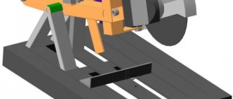
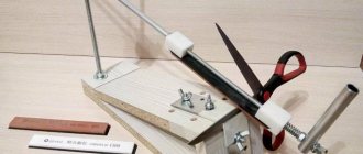
DIY tool holder
For the tool holder, you need to use metal plates with a thickness of at least 10 mm. The classic shape of the tool holder is square; the tool itself is fixed with clamping bolts. And the assembled holder is attached to the slide with a large bolt, with a handle welded to the head.
Read also: Pilaf with zirvak in Uzbek recipe
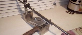
Guides for the machine
The guides can be made of a pipe with a diameter of 15 mm, a 10x10 mm square or a round rod. Studs with a diameter of 18 mm or more can be used as the caliper feed shaft and slide.
What should you consider during assembly?
For all types of homemade machines, the use of welded joints is used as the most reliable. However, when working with electric welding, the metal can be deformed, which can cause accuracy to be compromised. In order for the welding to be strong and correct, it is recommended to first make several test seams and only after checking proceed to the final connection of the parts.
Main purpose
The purpose of the bed is determined by its role among the components of the machine.
It is one of the main parts and is designed to perform the following functions:
- fastening and placement in a certain spatial order of all other parts and assemblies of the product;
- perception, distribution and transfer to the foundation of static and dynamic loads caused by the weight of parts and arising during the operation of the machine;
- creating conditions for moving the working parts of the machine and workpieces with the required accuracy along guides and work tables.
In addition, it also performs auxiliary functions - protecting structural elements from the influence of the external environment.
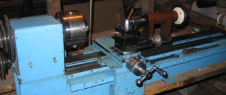
Headstock
The parts located in the headstock serve to support and rotate the workpiece during processing. There are also units here that regulate the speed of rotation of the part. These include:
- spindle;
- 2 bearings;
- pulley;
- gearbox responsible for adjusting the rotation speed.
The headstock is separate from the machine
The main part of the headstock in a lathe is the spindle. On its right side, facing the tailstock, there is a thread. Chucks that hold the workpiece are attached to it. The spindle itself is mounted on two bearings. The accuracy of the work performed on the machine depends on the condition of the spindle assembly.
Gearbox top view
In the headstock there is a guitar of interchangeable gears, which is designed to transmit rotation and torque from the output shaft of the gearbox to the feedbox shaft for cutting various threads. Adjustment of the caliper feed is carried out by selecting and rearranging various gears.
Bed repair
Despite the high quality of materials and precision manufacturing, during operation the frame experiences significant loads and inevitably wears out. These processes are most noticeable on the surface of the guides, which loses its geometric and strength properties.
To restore working properties, periodic or unscheduled repairs of guides are carried out. To perform the scraping operation, moving parts are removed from the machine, and the bed itself is fixed on a rigid, massive foundation. The operation is then carried out in the following sequence:
- the linearity of the longitudinal and transverse profile is checked using a frame level;
- if the deviation exceeds 0.02 mm per linear meter, scrape one of the guides using a ruler and paint for verification;
- in parallel, the degree of inversion is controlled;
- after bringing the deviation to the specified values, they move to the second guide.
After scraping, the surface is polished.
The basis of any success is a solid foundation!
Modern machines are subject to increasingly high demands on processing speed and accuracy. But the high speed of processes and complex metal cutting inevitably create vibrations in the frame, which negatively affects the quality of the machined surface and also shortens the service life of the tool.
A mineral cast frame absorbs these vibrations approximately 6 times faster than a comparable cast iron frame and 10 times faster than a comparable steel frame.
Tooling machines on mineral casting beds, such as turning, milling and grinding, operate with significantly greater precision and achieve a higher surface quality of the workpiece. Tool wear is also noticeably reduced.
Grinding the guides
During grinding, operations are performed in the following sequence:
- saw down and clean out surface nicks and burrs;
- the bed is fixed to the plate longitudinally - the planing installation;
- a level placed at the level of the tailstock is used to measure the degree of curvature of the guides;
- if necessary, correct the sagging of the structure using compensating spacers and wedges;
- the tortuosity is re-measured, the measurement results must coincide with the original ones;
- The surface of the guides is ground with a fine abrasive grinding bowl.
After restoring the surface of the guides, the machine is mounted on its own foundation and the previously removed moving parts are attached to it.
Over the life of the machine, this operation is performed several times, returning it to active production use.