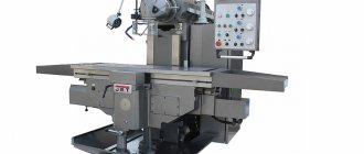
Machine
Description Designed for milling all kinds of parts made of steel, cast iron and non-ferrous metals, mainly with face and end mills.
This machine can process vertical, horizontal and inclined planes, grooves, corners, frames, gears, etc.
The technological capabilities of the machine can be expanded by using a dividing head and a rotary round table.
Specifications
- Working dimensions of the table, mm 400x1600
- Maximum table stroke, mm:
- — longitudinal 900
- — transverse 320
- — vertical 420
- Distance limits from the table axis to the vertical guides
- bed, mm 250. 570
- Head rotation angle, degrees 45
- Number of spindle speeds 18
- Spindle hole diameter, mm 29
- Distance limits from the end of the spindle to the table surface, mm 30. 520
- Distance from the spindle axis to the vertical guides of the frame, mm 450
- Limits of spindle revolutions per minute are 31.5. 1600
- Number of longitudinal, transverse and vertical table feeds 18
- Table feed limits, mm/min. :
- - longitudinal 25. 1250
- - transverse 25. 1250
- - vertical 8. 400
- Speed of rapid table movement, mm/min. :
- — longitudinal 3000
- — transverse 3000
- — vertical 1000
- Vertical spindle travel, mm 85
- Main electric motor power, kW 10
CASSPORTIZATION
Purpose of the technical device.
Vertical cantilever milling machines 6Р12, 6Р12Б, 6Р13, 6Р13Б are designed for milling all kinds of parts made of steel, cast iron, and non-ferrous metals with end, end, cylindrical, radius and other cutters.
The machines can process vertical, horizontal and inclined planes, grooves, corners, frames, gears, etc.
On machines 6Р12Б and 6Р13Б you can process parts made of light alloys.
Specifications.
Accuracy class according to GOST 8-71 – N.
Working surface dimensions, mm – 1250x320 for 6Р12, 6Р12Б (1600х40 for 6Р13, 6Р13Б)
Number of T-slots – 3
Maximum table movement, mm:
longitudinal mechanical – 800 for 6Р12, 6Р12Б (1000 for 6Р13, 6Р13Б)
longitudinal manually – 800 for 6Р12, 6Р12Б (1000 for 6Р13, 6Р13Б)
transverse mechanical – 240 for 6Р12, 6Р12Б (300 for 6Р13, 6Р13Б)
manual transverse – 250 for 6Р12, 6Р12Б (320 for 6Р13, 6Р13Б)
vertical mechanical – 410
vertical manual – 420
The smallest and greatest distance from the end of the spindle to the table during manual movement, mm – 30-450 for 6Р12, 6Р12Б (30-500 for 6Р13, 6Р13Б)
Distance from the spindle axis to the vertical guides of the frame, mm - 350 for 6Р12, 6Р12Б (420 for 6Р13, 6Р13Б)
Moving the table by one division of the dial, mm – 0.05
Moving the table per 1 turn of the dial, mm:
longitudinal and transverse – 6
vertical – 2
Maximum weight of the workpiece, kg - 250 for 6Р12, 6Р12Б (300 for 6Р13, 6Р13Б)
Machine dimensions, mm:
length - 2305(6Р12); 2340(6Р12Б); 2560(6Р13); 2600(6R13B)
width -1950(6Р12); 1950(6R12B); 2260(6Р13); 2260(6R13B)
height - 20206Р12); 2020(6R12B); 2120(6Р13); 2120(6R13B)
Machine weight, t – 3.12 (6Р12); 3.18(6Р12Б); 4.20(6Р13); 4.27(6Р13Б)
List of controls
The following components of the machine are no less important than the previous ones:
Gearbox or gearbox
The equipment has a total of 18 gear indicators. This is a separate unit. Usually located on the console, on the left side. The gear shift device is located directly on the console. The front part is equipped with a so-called dial - it is used to apply certain gear indicators to the surface. Marks allow you to easily set feed rates for the working surface, in horizontal or vertical planes.
Swivel head
It looks like a spindle that is positioned vertically. Supplied with an additional roller for receiving. The spindle moves along the axis using a special flywheel, the latter is placed inside a special sleeve. The handle is located inside the left side of the sleeve. This makes it easy to clamp if necessary.
Gearbox
A total of 18 numbers are used on which the spindle rotates. Installed inside the frame body. The shafts of this box are mounted on ball bearings. The plunger pump that regulates lubrication is located on one of these parts.
Sled with work table
The slide is clamped to the console using eccentric clamps. The movement begins from a screw located transversely. At the next stage, everything moves to guides in the shape of a rectangle, console type.
The table also moves using the guides mentioned earlier. He is the final component of the serve chain, which respects the longitudinal position. The rotating screw is responsible for the implementation of such a scheme. The claw clutch handle must be turned on for movement to begin.
The table can be configured in three modes: pendulum, automatic and semi-automatic.
The pendulum mode is controlled using cams. The parts are mounted on the side surface of the table, located in front. If a blockage occurs at the longitudinal stroke lever, the pendulum operating mode cannot be stopped, this leads to damage to the unit.
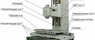
List and location of main parts
The 6Р82Ш milling machine consists of the following basic units:
- A foundation slab equipped with vibration bearings of the OV series with rubber-metal elements in accordance with TU 4192-003-96952067-13.
- Vertical bed with guides.
- Instrument console with movable slides.
- Electric motors for driving the main movements and driving the coolant supply station.
- Rotating plate (trunk).
- Desktop.
- The gearbox mechanism, which is located in the inner part of the hollow frame.
- Feedbox mechanism.
- Rotating and (or) additional overhead head.
- Controls for the operation of the machine.
- Containers for cutting fluid.
With this arrangement, the machine has the ability to move the work table in all three coordinates. All controls are located on a rotating instrument panel, on the side of which a 24 V local lighting lamp is installed. To achieve the necessary rigidity and eliminate vibrations (especially during power milling), the center of gravity of the machine is located below the working surface of the movable table.
Kinematic scheme
The main component of the movement of the device is an electric motor with a power of 7.5 kW. Through an elastic coupling, the movement from this device passes to one of the shafts. From the first shaft to the second, energy is transferred through a gear drive.
A block is placed at the second shaft, complemented by gear-shaped wheels. Thanks to this part, the movement moves to the third shaft. The device supports three different transmission speeds. Gear screws are also involved in this process.
The main feedbox operates at 18 speeds. If you turn on the friction clutch, the tool can be quickly moved around the table, regardless of the technical characteristics. In this case, the process is also organized using the main electric motor along with the shaft and gears.
Kinematic diagram
Initially, the movement is supplied from an electric motor through a clutch. From the latter, the spindle begins to move using three blocks with teeth. It is indicated in the product passport that a total of 18 speeds are allowed, which are transmitted from the gearbox to the spindle. There is a motor in the console that determines the transmission of rotation. It moves further into the console through the coupling.
The transmission speed is affected by the clutches near the engine. On the 6P12 machine it is impossible to turn on several speeds at once, thereby ensuring the reliability of the device and the specialists who work with it. The standard element that secures the kinematic system is the frame.
Repair and modernization
For efficient operation of the 6T13, the description of the machine in the documentation is illustrated with diagrams: kinematic, bearing arrangement, lubrication, slinging. The second part of the manual is devoted to electrical equipment, it contains a circuit diagram and specifications according to which spare parts should be selected.
Based on statistics, elements have been identified that are more often replaced by mechanical service in the event of breakdowns. The passport for the 6T13 machine contains drawings of wearing parts. Unification makes it possible to partially borrow spare parts for 6T13 milling machines from representatives of other series.
Before starting work on updating the 6T13 electrical equipment, the electrical connection diagram is checked for discrepancies in the markings of the wires in order to avoid wiring errors.
The 6T13 vertical cantilever milling machine can be upgraded in the following areas:
- installation of optical rulers and display devices (DRO) – increases convenience and reduces operator time;
- equipping the cabinet and control panels with modern electrical devices - frees up space, improves access, reduces replacement time, spare parts are available everywhere;
- replacing plunger pumps with electrically driven units increases the reliability of the lubrication system;
- It is possible to borrow a stepless feed drive from non-working representatives of the T series, equipped with CNC.
After modernization, changes are made to the electrical circuit and additional sheets are introduced.
In each case, an economic calculation of the feasibility and level of renovation is necessary, based on the condition of the milling equipment, the cost of spare parts, the planned load, and other factors.
Features of use and repair
Before starting work, it is necessary that the 6p12 milling machine be checked for possible defects in its main elements. Additionally the following is required:
- removing the protective layer from the unit after unpacking using a special solution;
- lubrication of device elements in accordance with the requirements of the passport;
- installation of a protective fence after fixing the cutter;
- mandatory check of the device at idle speed.
Common types of device malfunctions are:
- the presence of knocking noises in the bearing, which, if detected, require its replacement;
- humming of the electric motor due to its overheating, which, if detected, requires winding repair.
If repairing the electric motor winding does not eliminate overheating and humming during further operation, it is recommended to replace it with a new one.
The motor may not turn and make a loud noise. The reason lies in the fact that the voltage has disappeared in its phase. The problem can be solved by replacing the fuse links.
Specifications
To become familiar with the operational and performance characteristics of the 6P12 machine, it is necessary to study the equipment passport in detail. Since this model belongs to the professional category, before performing milling, the worker must undergo safety training and become thoroughly familiar with the operating principle of the elements and assemblies.
The weight of the machine with all installed equipment is 3120 kg. Its dimensions do not exceed 228*196.5*226.5 cm. When compared with similar models, you will notice that the dimensions of the machine are larger than standard. This must be taken into account when choosing an installation location.
The main technical characteristics of the 6P12 model are indicated in detail in the passport. But to select the correct operating mode, you should know the following machine parameters:
- desktop dimensions – 125*32 cm;
- the maximum permissible weight of the workpiece being processed is 250 kg;
- desktop progress. In the longitudinal direction – up to 80 cm; in transverse – 25 cm;
- maximum vertical displacement of the table surface – up to 42 cm;
- the nominal speed of the spindle head varies from 40 to 2000 rpm;
- number of spindle speeds – 18;
- the spindle quill can change its position by 70 mm;
- the number of table feeds is the same for all directions (longitudinal, transverse and vertical) and is 22.
The power of the electric motor of the main spindle drive is 7.5 kW. To activate the high-speed clutch of the working table, the 6р12 vertical milling machine has in its design special gears connected to the power plant shaft. — price 1,317,000 rub. “> 6P12 vertical milling machines are designed for processing all kinds of parts made of steel, cast iron, difficult-to-cut and non-ferrous metals, mainly with face and end mills. They can be used to process vertical, horizontal and inclined planes, grooves, corners, frames, and curved surfaces. The machines are equipped with a vertical quill spindle. The table moving in a horizontal plane is mounted on a console rack moving vertically along the guides. They are equipped with copying devices and relatively simple CNC devices. For processing curved surfaces, the machines are equipped with a special copying device. Processing of curved surfaces is carried out using copiers, the contour of which is felt by the tip of an electric contact sensor for table movement. Coolant is supplied by the engine of a centrifugal vertical pump through pipelines through a nozzle to the tool. The rotating spindle head of 6P12 vertical milling machines is equipped with a mechanism for manual axial movement of the spindle sleeve, which allows processing of holes whose axis is located at an angle of up to ±45° to the working surface of the table. The drive power and high rigidity of the machines allow the use of cutters made of high-speed steel, as well as tools equipped with plates made of hard and super-hard synthetic materials. Vertical milling machines 6Р12 are used in single and mass production. Machine accuracy class N according to GOST 8-77.
Unit design and its features
The unit consists of the following elements:
- electric motor located inside a vertical box;
- a control unit located inside a vertical box, like an electric motor;
- a cast iron frame on which all other mechanisms are mounted;
- milling head equipped with a rotating mechanism;
- cooling unit with electric pump.
The working table of the unit itself can change its location along both vertical and horizontal axes. The device is characterized by dimensions that exceed the standard dimensions of machine tools.
The 6P12 milling machine table can adjust the axis you need
The device features are described as follows:
- the spindle head has an axis offset, which allows the master to mill products at an angle of 450;
- the presence as an additional element of a copying mechanism intended for milling parts according to a previously created sample;
- The power of the device allows you to process workpieces with cutters containing high-speed steel.
Information about the manufacturer of the vertical milling machine 6Р12
The machine was produced at the Gorky plant. This government agency is known all over the world, since it was from its assembly line that the best types of equipment for industrial purposes came off. The plant was founded in 1931, and a year later it began producing models of equipment designed to work with metal-cutting structures.
Specifically, the P series began to appear in 1972. In the same year, modifications to the 6P12 appeared, followed by the improved 6P12B. A few years later, equipment began to be produced with a more unified scope of use - such machines were part of the M series.
Now the Gorky Plant is no longer engaged in the production of equipment, but at the same time, the devices developed by its employees can be purchased in the Russian Federation. Since 2007, most of the devices have been supplied to the foreign and domestic market by the so-called Machine Park. Engaged in the production of classic and modified versions of the console-milling type.
CNC system
The CNC milling machine 6R13F3, 6R13RF3, 6T13F3 was equipped by the manufacturer with a CNC system model NZZ-2M. CNC allows you to process products in program control mode simultaneously in three coordinates: longitudinal, transverse (moving the table and slide with the workpiece) and vertical (moving the slider with the tool). Programmable vertical movement (Z coordinate) is carried out by the movement of the slider. The console of the CNC milling machine 6R13F3, 6R13RF3, 6T13F3 has only installation movement, which excludes positioning and operation in the tracking mode of the console, which has a significant mass. The processing accuracy increases, since the console is always clamped during the cutting process.
Machine drives
The CNC milling machine 6R13F3, 6R13RF3, 6T13F3 is equipped with servo-controlled feed drives with high-torque DC electric motors. The use of servo adjustable drives with DC motors ensures a rapid table movement speed of up to 4.8 m/min and eliminates part rejection during contour processing in the event of a feed drive failure along one of the coordinates. Centralized lubrication of guides has been introduced. The machine uses an electromechanical tool clamping device, which provides a stable clamping force of 2000 kg. For remote equipment there is ready-made electrical wiring with plug connectors.
Designation
The alphanumeric index of a CNC milling machine 6R13F3, 6R13RF3, 6T13F3 means the following: number 6 is a milling machine; letter P, T, M – modification of the machine, number 1 – indicates a vertical milling machine, number 3 – standard size of the machine (table size), F3 – presence of a CNC system.
| Specifications | Options |
| Dimensions of the working surface of the table, mm | 400 x 1600 |
| Accuracy class according to GOST 8-71 | P |
| Roughness of the processed surface Rz, µm | 20 |
| Maximum load on the table (center), kg | 300 |
| Maximum longitudinal movement of the table (X), mm | 1000 |
| Maximum lateral movement of the table (Y), mm | 400 |
| Maximum vertical installation movement of the table, mm | 420 |
| Maximum vertical movement of the slider (Z), mm | 250 |
| Working feed limits. Longitudinal, transverse, vertical, mm/min | 3 — 4800 |
| Speed of rapid movement of the table and slider, mm/min | 4800 |
| Distance from the end of the spindle to the table, mm | 70 — 490 |
| Distance from the spindle axis to the vertical guides of the bed, mm | 500 |
| Feed per impulse, mm | 0,01 |
| Positioning accuracy along the X axis, mm | 0,065 |
| Positioning accuracy along the Y, Z axis, mm | 0,040 |
| Largest drilling diameter, mm | 30 |
| The largest diameter of the end mill, mm | 40 |
| Largest diameter of end mill, mm | 125 |
| Spindle speed, min-1 | 40 — 2000 |
| Number of spindle speeds | 18 |
| Maximum torque, kgf.m | 62,8 |
| Spindle end GOST 836-72 | 7:24 |
| Main motion drive electric motor, kW | 7,5 |
| Electric feed drives along the X, Y, Z axes, kW | 2,2 |
| Electric drive for adjustment movement of the console, kW | 2,2 |
| Electric drive for tool clamping, kW | 0,18 |
| Electric drive of the cooling pump, kW | 0,12 |
| Lubrication motor, kW | 0,27 |
| Total power of electric motors, kW | 16,87 |
| Overall dimensions of the machine (L x W x H), mm | 3450 x 3970 x 2965 |
| Weight of the machine with electrical equipment, kg | 4450 |
Model designation
Considering the designation of the 6P12 vertical milling machine, let’s decipher it:
- 6 – denotes milling type equipment.
- The letter "P" is the manufacturer's designation.
- 1 – designation of vertical group
- 2 – standard size of installed steel. A vertical machine has a table on which the workpiece is placed.
The transcript fully describes the features of using the cantilever vertical milling machine 6P12. However, by decoding it is possible to determine only the location of the spindle, but, for example, the power of the motor or the features of the electrical circuit cannot be determined - for this, information from the passport is used. The decoding of the name of the machine is similar to the 6T12 model: the only difference is the name of the manufacturer’s plant.
Operating instructions for vertical drilling machine 6Р12
The operating instructions for the 6P12 vertical milling machine contain information necessary both for the operating personnel of this machine and for the employee directly involved in working on this machine. This manual is an electronic version in PDF format of the original paper version with some chapters missing.
You can download the “Operating Instructions for Vertical Milling Machine 6P12” for free in good quality from the link below:
Features of disassembling 6P11 machines
On machines, it is difficult to dismantle the feed box and gearbox from the console. Dismantling requires complete disassembly of the console, which must be carried out in the following order:
- unfasten the sled strips and the table cross-travel nut bracket, remove the table;
- lift the console all the way up and place a reliable support under it;
- open the cover and remove the nut from the upper end of the vertical movement screw; Unfasten the screw casing flange from the bottom of the console; unfasten the column from the base and screw it onto the screw; remove the screw with the casing and bevel gear from the console;
- Unfasten and remove the feed switch mechanism;
- unfasten and remove the reverse box from the console;
- disconnect the lubrication lines from the pump;
- remove the overspeed handle and console cover;
- drain the oil from the console cavity;
- remove the feed box along with the gearbox.
Kinematic diagram
The kinematic diagram of the equipment is quite standard in appearance; it is necessary for the engineer to understand the general scope of the work and the connection of structural parts. Judging by it, you can understand how movement is transmitted from one node to another and why the characteristics change and the like.
The drive is powered by a flange electric motor. They are connected using a high-quality coupling. Spindle revolutions per minute can be a different number. This characteristic is controlled using three gear blocks. They are located along the shafts, which can be easily seen in the kinematic diagram. The gearbox gives the desired display to the spindle. The device's operating sheet states that there can be a total of 18 speeds.
Please note that:
- feed drive from the engine, which is located on the console;
- accelerated movements are made by the high speed clutch;
- friction clutch works by means of gears;
- the feed clutch is connected to the clutch;
- the clutch and clutch can be turned on simultaneously, since they are connected.
The kinetic diagram indicates the basis, the main part is the frame. It is fixed with pins on the base of the machine.
Feed mechanism
Typically, feed mechanisms consist of several shafts. And each device has its own operating features:
- The 6th shaft is mounted on three ball bearings.
- The clutch of this part is adjusted as it moves. To do this, you need to use screws screwed into the flange.
- The fifth shaft is installed using the same rule. Tightening the nut from the left end is enough to adjust this part.
- The fourth shaft is located on three supports, thereby increasing rigidity.
- The spline type of devices includes shafts 2, 3 and 4. They are involved in the movement of gear blocks.
The gear shift mechanism, in fact, becomes a separate independent unit. On the surface there is dial 1, where all 18 spindle revolutions are applied.
Design of the main components of the 6T12 cantilever milling machine
bed
The bed is the base unit on which the remaining components and mechanisms of the machine are mounted.
The frame is rigidly fixed to the base and fixed with pins.
Rotating head of cantilever milling machine 6T13-1
The rotating head (Fig.) is centered in the annular recess of the bed neck and is attached to it with four bolts that fit into a single groove in the bed flange.
The spindle is a two-support shaft mounted in a retractable sleeve. The axial play in the spindle is adjusted by grinding rings 3 and 4. Increased play in the front bearing is eliminated by grinding half rings 5 and tightening the nut.
The adjustment is carried out in the following order:
- the spindle sleeve extends;
- flange 6 is dismantled;
- half rings are removed;
- a screw plug is removed from the right side of the head body;
- through the hole, unscrewing screw 2 unlocks nut 1;
- Nut 1 is locked with a steel rod. By turning the spindle by the nut, the nut is tightened and this moves the inner race of the bearing. After checking the play in the bearing, the spindle is run in at maximum speed. When operating for an hour, the heating of the bearings should not exceed 60° C;
- the size of the gap between the bearing and the spindle collar is measured, after which the half rings 5 are ground to the required amount;
- the half rings are put in place and secured;
- Flange 6 is screwed in.
To eliminate radial play of 0.01 mm, the half rings must be ground by approximately 0.12 mm.
Rotation is transmitted to the spindle from the gearbox through a pair of bevel and a pair of cylindrical gears mounted in the head.
The bearings and gears of the rotary head are lubricated from the frame pump, and the spindle bearings and the sleeve moving mechanism are lubricated by extrusion.
Gearbox
The gearbox is mounted directly in the frame body. The connection of the box to the electric motor shaft is carried out by an elastic coupling, allowing misalignment in the motor installation of up to 0.5-0.7 mm.
The gearbox can be inspected through the window on the right side.
The gearbox is lubricated by a plunger pump (Fig. 9), driven by an eccentric. Pump capacity is about 2 l/min. Oil is supplied to the pump through a filter. From the pump, the oil flows to the oil distributor, from which it is discharged through a copper tube to the pump control eye and through a flexible hose to the rotary head. The gearbox elements are lubricated by splashing oil coming from the holes in the oil distributor tube located above the gearbox.
Gearbox
The gearbox allows you to select the required speed without sequentially passing through intermediate stages.
Rack 19 (Fig. 10), moved by shift handle 18, through sector 15 through fork 22 (Fig. 11) moves the main roller 29 with shift disc 21 in the axial direction.
The shift disk can be turned by the speed indicator 23 through the bevel gears 28 and 30. The disk has several rows of holes of a certain size located against the pins of the racks 31 and 33.
The racks engage in pairs with gear 32. A shift fork is attached to one of each pair of racks. When moving the disk by pressing on the pin of one of the pair, reciprocating movement of the slats is ensured.
In this case, the forks at the end of the disk stroke occupy a position corresponding to the engagement of certain pairs of gears. To eliminate the possibility of hard stop of the gears when switching, the pins of 20 racks are spring-loaded.
Fixation of the dial when choosing a speed is ensured by ball 27, which slides into the groove of sprocket 24.
The spring 25 is adjusted by the plug 26, taking into account the clear fixation of the dial and the normal force when turning it.
Handle 18 (see Fig. 10) is held in the on position by spring 17 and ball 16. In this case, the handle tenon fits into the groove of the flange.
Correspondence of speeds to the values indicated on the indicator is achieved by a certain position of the bevel wheels along the mesh. Correct engagement is established by cores at the ends of the mating tooth and cavity or by setting the pointer to the speed position of 31.5 rpm and the disk with forks to the speed position of 31.5 rpm (for machine models 6T12B the corresponding speed is 50 rpm) . The gap in the engagement of the conical pair should not be more than 0.2 mm, since the disk can rotate up to 1 mm due to this.
The gearbox is lubricated from the gearbox lubrication system by splashing oil.
Location of controls for the 6P12 cantilever milling machine
Location of controls for the 6P12 cantilever milling machine
List of controls for the 6P12 cantilever milling machine
- Stop button (duplicate)
- “Spindle Start” button (duplicate)
- Spindle speed indicator arrow
- Spindle speed indicator
- “Quick table” button (duplicate)
- "Spindle pulse" button
- Light switch
- Rotate the head
- Spindle sleeve clamp
- Automatic cycle sprocket
- Handle for turning on longitudinal table movements
- Table Clamps
- Handwheel for manual longitudinal movement of the table
- “Quick table” button
- Spindle start button
- Stop button
- Switch for manual or automatic control of longitudinal table movement
- Flywheel for manual lateral movements of the table
- Limb of the table transverse movement mechanism
- Vernier ring
- Handle for manual vertical movement of the table
- Button for fixing the feed switch fungus
- Feed switch mushroom
- Table feed indicator
- Table feed indicator arrow
- Handle for turning on the transverse and vertical table feeds
- Clamping the slide on the console guides
- Handle for turning on longitudinal movements of the table (duplicate)
- Handle for turning on the transverse and vertical table feed (duplicate)
- Handwheel for manual longitudinal movement of the table (duplicate)
- Spindle rotation direction switch “left-right”
- Cooling pump switch "on off"
- Input switch “on-off”
- Spindle speed shift knob
- Switch for automatic or manual control and round table operation
- Clamping the console on the frame
- Spindle sleeve extension handwheel
- Clamping the head on the frame
Specifications
Information about some characteristics of the machine is already included in the marking. So, the number “6” means the type of machine - milling, the letter “P” indicates the generation (the fifth, after generations B, K, N, M), and the index “13” indicates the size of the table - they are 1600 * 400 mm. Other important data includes:
- The height of the spindle above the table surface is from 30 to 500 mm;
- Maximum table movement: in the vertical plane - 430 mm; in the longitudinal - 1000 mm; in the transverse - 400 mm.
- The amount of table movement per dial division is 0.05 mm in any plane.
- The table's idle speed is up to 4000 mm/min in the horizontal plane and up to 1330 mm/min in the vertical plane.
- The feed rate is up to 12.5-1600 mm/min in the horizontal plane and up to 4.1-530 mm/min in the vertical plane.
- The maximum cutter diameter for roughing is 200 mm.
- There are 18 spindle speeds in total.
- Spindle rotation speed - from 31.5 to 1600 rpm.
- The maximum rotation angle of the spindle head is 45 degrees.
- The drive power of the main movement is 11 kW.
- Feed drive power - 3 kW.
- The maximum weight of the workpiece or part being processed is 630 kg.
- Overall dimensions of the machine: height - 2430 mm; length - 2570 mm; width - 2250 mm.
- The weight of the equipped machine is 4300 kg.
Spare parts for machines 6Р12, 6М82, 6Р82, 6М12П
StankoPromServis LLC supplies spare parts for cantilever milling machines of the 6P12 series. We offer comprehensive supplies of parts and assemblies for your machine park. Spare parts 6P12 are always available in our warehouse. Our company is also a manufacturer of parts for 6P12 machines and analogues.
- Model 6P12 machines are designed for drilling, milling and boring workpieces of any shape from various materials - steel, cast iron, non-ferrous metals, as well as their alloys. Working surface of the table, mm 1250x320.
- Table lift screw 6P12 - on milling machines is designed to move the table with the workpiece installed on it along a vertical axis to the cutting zone.
- Running screw 6P12 (longitudinal screw of the table) - installed in the work table of the milling machine and serves to move the table from right to left and back, designed to move the workpiece to the milling zone. The thread profile of the lead screw is trapezoidal. As a rule, the lead screw is supplied complete with two nuts.
- The 6P12 gearbox makes it possible to change the number of spindle revolutions while maintaining a constant speed of rotation of the electric motor shaft.” Its structure is similar to the gearbox of a lathe. The milling gearbox supplied by StankoPromServis LLC includes 4 shafts assembled with gears, which are mounted in the machine body.
- The 6P12 feed box provides working feeds and rapid movements of the table, slide and console. The feed box is used to change table feeds in the vertical, longitudinal and transverse directions.
- The 6P12 gearbox allows you to select the required speed without sequentially passing through intermediate stages.
- The milling head is the part of the milling machine that carries the spindle. There are horizontal, vertical and inclined, including rotary.
- Friction shaft 6P12 (overload clutch) is called the friction shaft of the feed box of the VI axis. The friction shaft assembly kit includes friction discs, gears, cam clutches, cups (friction clutches).
- Friction discs 6Р12 are an integral part of the friction shaft. The kit includes external and internal disks, total quantity – 25 pcs.
- The milling machine spindle is installed in horizontal milling machines in the machine body, in vertical milling machines - in a rotary milling head. This is a steel shaft that serves to secure a milling mandrel with a disk cutter or a long steel rod with a thread at the end, with an end mill, and to impart a rotational movement (cutting movement) to the cutting tool (mill). At the front, the spindle hole has a conical shape with a specific taper number so that the conical part of the milling mandrel fits tightly into it. This ensures precise installation of the cutter relative to the spindle and its strong fastening. Using a gearbox, the spindle is set to different speed modes of rotation.
- Gears 6P12 (bevel gear 6P12, gear wheel 6P12, hypoid pair 6P12, gear-clutch, bevel gears, hypoid pair) is a cylindrical or conical part, with teeth that mesh with the teeth of another gear and drive various mechanisms. Traditionally, a pinion is the name given to the smaller of the gears in a mating pair. But in colloquial speech, any gear has long been called a gear. StankoPromServis LLC offers any factory gears for milling machines of the 6P12 series.
StankoPromServis LLC also offers repair services for machines of the 6P12 series.
Our staff has an experienced team for repairing machines of various modifications. Machine inspection, troubleshooting, machine disassembly, replacement of worn parts of 6P12 machines. Repair and maintenance services for your machine park. 6Р12 — Vertical milling machine
Technical characteristics of the 6Р12 machine:
Model 6P12 machines are designed for drilling, milling and boring workpieces of any shape from various materials - steel, cast iron, non-ferrous metals, as well as their alloys. Vertical milling machines 6P12 are designed for processing all kinds of parts. They can be used to process vertical, horizontal and inclined planes, grooves, corners, frames, and curved surfaces.
Machine design features
• the 6Р12 machine is equipped with a chip protection system; • a mechanism is installed that proportionally slows down the feed; • a mechanism is installed that allows you to adjust the gap in the longitudinal feed screw pair; • a clutch is installed that protects the feed drive from unwanted overloads; • when stopping the electric magnetic coupling, the horizontal spindle is braked; • mechanical fastening of the tool in the spindle
| Working surface of the table, mm | 1250x320 |
| Table movement, mm, maximum: | — longitudinal 800 - transverse 320 - vertical 420 |
| per one division of the dial (longitudinal, transverse, vertical), mm | 0,05 |
| one turn of the dial | - longitudinal and transverse 6 - vertical 2 |
| Movement of the spindle quill by one division/revolution of the dial, mm | 0,05 / 4 |
| Spindle sleeve movement (vertical) | 70 |
| Diameter of cutters during roughing, mm, maximum | 160 |
| Distance, mm: | from the end of the vertical (horizontal axis) spindle to the working surface of the table, mm 30-450 from the spindle axis to the bed guides 380 |
| Speed of rapid table movement, mm/min: | — longitudinal and transverse 4000 — vertical 1330 |
| Number of spindle speeds | 18 |
| Rotation speed of horizontal or vertical spindle, min | 1 31,5-1600 |
| Number of table feeds | 22 |
| Feed, mm/min | — longitudinal and transverse 12.5-1600 — vertical 4.1-530 |
| Spindle head rotation angle, degrees | 45 |
| power, kWt | main movement drive 7.5 feed drive 3 |
| Weight of the workpiece (including fixture), kg | 400 |
| Overall dimensions, mm | — length 2280 — width 1965 — height 2265 |
| Weight, kg | 3 250 |
Kinematic diagram of a 6R13RF3 CNC milling machine
Kinematic diagram of a CNC milling machine 6р13рф3
Mechanisms and movements in the machine
Bed A (Fig. 139) has high rigidity due to the developed base, trapezoidal section in height, internal ribs and partitions. Turret head G has six spindles located at an angle of 60° relative to each other. One of the spindles is reinforced for heavy milling work. Console B moves along the vertical guides of the frame (Z' coordinate). The transverse slides B move along the horizontal guides of the console (coordinate Y' along the guides of the latter in the longitudinal direction - table D (coordinate X'). The frame contains a gearbox E. Transverse and vertical feed mechanisms are mounted in the console body, and a longitudinal feed mechanism is mounted in the slides .
Machine kinematics
Spindle VIII receives its main movement from the DC electric motor Ml through an elastic coupling and the gears of the gearbox and turret. Variation of the spindle speed is ensured in an automatic cycle due to a programmed change in the set voltage for the thyristor converter, as well as the movement of blocks B1 and B2 by means of hydraulic cylinders. The equation for the minimum spindle speed is pmin = 575 x (27/53) x (22/32) x (27/37) x (19/69) x (34/34) x (22/22) = 40 rpm, where 575 is the lowest shaft speed of the ML electric motor
To secure the mandrel with the tool, use a ramrod IX, which is mounted in the spindle hole. A thread is cut at the front end of the cleaning rod, and a conical ring Z= 20 is mounted at the rear end. When the mandrel engages with the latter, the wheel Z= 20 of shaft X engages with the latter.
A gear pump is connected to shaft II, which provides lubrication of the elements of the turret gearbox.
Turret
The turret consists of a base to which a rotating plate is attached by half rings. Six spindle housings are fixed at the end of the plate. The central shaft VI of the rotary plate is connected to a cross coupling with the output shaft V of the gearbox. A drive wheel Z = 34 with a guide toothed disk is attached to shaft VI. Rotation from the drive wheel through the gear i = 34/34 and the bevel pair i = 20/20 (or i = 22/22) is received only by the spindle VIII that is in the working position. The head is rotated to a given position by a hydraulic motor M2 (type G12-22) through gear pairs Z= 18-90, Z- 18-72, disk 1 with a lantern and a Maltese cross 2. Each spindle housing has a socket on the outside into which it fits a latch that can be extended upon command from the limit switches. This fixes the position of the turret head.
Vertical, longitudinal and transverse feeds
Vertical, longitudinal and transverse feeds and accelerated movements are carried out from stepper motors ШД5Д1 with hydraulic torque boosters E32G1824. The cross-feed rolling screw XVI (pitch p = 8 mm) receives rotation from motor 8 through two pairs of helical wheels i = 20/40, i = 21/35. The amount of minimum movement along the Y coordinate: (1/240) x (20/40) x (21/35) x 8 = 0.01 mm.
Vertical feed is carried out from the M4 engine through gears i = 27/54, i = 21/35. The amount of minimum movement along the y coordinate; (1/240)(20/40)(21/35) x 8 = 0.01 mm.
Vertical feed is carried out from the M4 engine through gears i = 27/54, i = 39/65 and the rolling screw nut XXIII (pitch p = 3 mm). The spring hydraulic coupling M protects the console B from spontaneous lowering when the machine is stopped. The console is equipped with a clamping device powered by the CP and operating in the absence of vertical movement.
Longitudinal feed is carried out from the M5 engine through a backlash-free gearbox i = 27/45, i = 26/52 and a rolling screw nut XX (pitch p = 3 mm), the amount of longitudinal stroke is limited by the cams.
The kinematic chains for rapid feeds are the same as for working feeds. The manual feed handle sockets have limit switches for locking. When the handle is pulled out of the socket, the electrical circuit of the mechanical feed opens.
Device characteristics
The 6р12 device has the following technical characteristics:
- quill movement 7 cm;
- vertical feeds from 4.1 to 529 mm/min;
- travel of the transverse table is 250 mm, vertical - 420, longitudinal - 800;
- the spindle operates at a frequency of 40-2001 rpm;
- the number of spindle speeds is 18;
- 22 serves;
- the desktop has dimensions of 125*31 cm;
- the permissible weight of the workpiece is 250 kg;
- speed from 4.1 to 329 meters per minute;
- speeds of transverse and longitudinal feeds in the range from 12.5 to 1601 mm/min
The milling machine's passport contains information about its weight. Weight is about 3120 kg.
Main characteristics
The location of the spindle determines the position of the gearboxes. The main characteristics are:
- The working plane of the table has dimensions of 1250 by 320 mm.
- There is a feed box for moving the workpiece. The passport, which was included with the delivery of the vertical milling 6P12, also indicates the possibility of adjusting the distance between the spindle overhang and the installed workpiece.
- The instruction manual indicates that the spindle can be located at a distance of 30-450 mm from the table. In this case, you should take into account the dimensions of the part.
- The gearbox allows you to adjust the spindle speed in the range from 31.5-1,600 min-1. To rotate the spindle, an electric motor with a power of 11 kW and a table drive of 3 kW are installed. The electrical circuit determines the placement of the motor on the spindle head.
- You can also speed up processing using an electric drive. The electric drive allows you to speed up the movement of the table. The electrical circuit provides for the possibility of moving the workpiece in the vertical direction. The longitudinal and transverse shafts are made of high-strength steel; work can be carried out with manual or automatic feed
- The characteristics of the supporting structure make it possible to support workpieces weighing up to 550 kg. Operation involves relocation to process all surfaces.
- The electrical circuit of the model is quite complex. Looking at the electrical circuit, we note two control units: one is located in front of the table, the second is located on the spindle
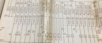
Electrical diagram of the machine
- The dimensions of the vertical milling 6P12 are as follows: 2280 by 1965 and 2265 mm.
- Weight is 3,250 kg. The operating instructions provide for the installation of a 6P12 vertical milling machine on a rigid base. The design of such equipment provides for the removal of vibration loads to the base.
At the time of release, the model had a high technical performance indicator. In addition, the electrical circuit and the diagram of the main components determine the high maintainability of the structure.