Assembling an electrical circuit with your own hands is not at all difficult if you have the proper level of knowledge in electrical engineering, even excellent knowledge of electrical engineering.
As you understand, this business is not for beginners and those who do not understand anything about electrical circuits. Let's analyze the stages of work using the example of a milling machine and find out what the circuit diagram of a milling machine is.
Electrical circuit diagram of the 6P11 cantilever milling machine
Kinds
There are the following types of electrical circuits:
- structural, which determines the relationship of parts of electrical equipment;
- functional, defining electrical processes in a separate unit, completely for a CNC machine;
- the fundamental one, which reflects all the elements and gives an idea of the principle of operation;
- installation plan connections for electrical connections;
- location of parts of electrical devices, conductor and cable products.
The technical documentation of the device usually contains a circuit diagram and electrical equipment layout diagrams. It is carried out without adherence to scale and without indicating how individual elements are actually located.
Operating principle
The principle of operation is based on displaying the operation of any final receivers of electrical energy from the operation or interaction of other components included in this circuit diagram of the milling machine.
In our example, this is testing magnetic starters depending on the position of the control handles, the position of limit switches, the state of thermal relays, etc.
Schematic diagram of the electrical control of a vertical milling machine
↑ Preface
After I assembled my small machine without significant expenditure of effort, time and money, I became seriously interested in this topic. I watched on YouTube, if not all, then almost all the videos related to amateur machines. I was especially impressed by the photographs of products that people make on their “ home CNC
”.
I looked and made a decision - I will assemble my own large machine! So, on a wave of emotions, without thinking everything through, I plunged into the new and unknown world of CNC
.
I didn't know where to start. Vexta stepper motor
by 12 kg/cm, by the way with the proud inscription “made in Japan”.
While he was traveling across Russia, he sat in the evenings on various CNC forums and tried to decide on the choice of a STEP/DIR controller
and a stepper motor driver.
I considered three options: on the L298
, on field workers, or buy a ready-made Chinese
TB6560
about which there were very conflicting reviews.
For some it worked without problems for a long time, for others it burned out at the slightest user error.
Someone even wrote that it burned out when he slightly turned the shaft of the motor connected to the controller at that time. Probably the fact of the unreliability of the Chinese played in favor of choosing the L297+IRFZ44
, which is actively discussed on the forum. The scheme is probably really indestructible because... The driver's field amperes are several times higher than what needs to be supplied to the motors. Even though you have to solder it yourself (that’s just a plus), and the cost of the parts was a little more than a Chinese controller, but it’s reliable, which is more important.
I'll digress a little from the topic. When all this was done, the thought did not even arise that I would ever write about it. Therefore, there are no photographs of the assembly process of mechanics and electronics, only a few photos taken with a mobile phone camera. Everything else was clicked specifically for the article, in already assembled form.
Is it possible to assemble it with your own hands?
Before assembling the circuit yourself, you must first of all remember that the upcoming work involves electricity, and compliance with safety rules during its production is extremely important!
Required materials and tools
What we need:
- the basic electrical circuit of the milling machine itself;
- a set of constituent elements (magnetic starters, limit switches, transformers, control buttons, toggle switches, relays, etc.;
- an electrician's kit, which includes the necessary elements (pliers, screwdrivers, markers, electrical tape, etc.);
- cable products (cables, installation wires of different sections);
- electrical signal tester or multimeter.
Step by step assembly
It is advisable to start the assembly with the installation of the main components, first install the cables to the electric drives, wires to the magnetic starters. Then gradually move on to secondary control circuits, blocking, signaling, and protection circuits.
The ends of the cables and wire cores must be terminated and marked in accordance with the circuit diagram of the milling machine. This is extremely important because it will save more time and effort during commissioning. And you need to remember about those who will operate the machine after you.
Connection and service check
After installation, you need to make sure that all main work is completed and all foreign objects are removed from the operating area of the machine.
After power is supplied to the machine, you can begin to check its functionality. Check whether it is controlled by handles and control buttons, whether the spindle motor is braking, whether the longitudinal movement of the table is controlled, etc.
Possible errors and ways to fix them
- the engine hums when starting, but does not rotate - there is no voltage in one of the phases of the electrical network - check with a multimeter where the break occurred (fuse links, circuit breaker, thermal relay, connecting cable);
- when rotating, the electric motor hums and overheats - interturn short circuit, short circuit between phases - replace the electric motor or repair the winding;
- Thermal protection is triggered - the electric motor is overloaded - reduce the load to the rated value.
More detailed faults relate to commissioning work, there are many of them and this is material for an article of a different profile.
Operation of the circuit under automatic control
Automatic control is used only for the longitudinal movement of the table.
The machine can perform the following automatic cycles:
- Right jump with reverse
- Left jumping with reverse
- Pendulum
With a pendulum cycle, the working feed automatically alternates with rapid feed in each direction.
To operate on an automatic cycle, the PU switch must be set to the “automatic cycle” position.
In addition, it is also necessary to mechanically switch the roller present in the machine slide from the “manual control” position to the “automatic cycle” position. In the last position of the roller, the longitudinal stroke cam clutch is locked and the 4KA limit switch is pressed. This ensures control of the longitudinal movement of the table only from command devices 1KA and 3KA with interlocked transverse and vertical feeds.
To explain the operation of the circuit in an automatic cycle, we will analyze the execution of a right jump cycle with reverse. This cycle consists of automatic switching:
- From fast move to the right to feed to the right
- From feed to the right to fast move to the left
- From fast left to stop
To obtain rapid table movement at the beginning of the cycle, you must first make sure that the 3KA command device, which controls the operation of the PB starter during automatic cycles, is in an unpressed state, i.e., through its contact 48-26, the PB starter is powered.
If contact 3KA 48-26 is not closed, then it is necessary to rotate the sprocket with eight protrusions sitting on the shaft of the handle of the 1KA command device by one protrusion, after which contact 8KA 48-26 will close.
When you turn the handle of the 1KA command device to the right, the rapid movement of the table to the right will turn on, as the starters PP for the feed motor and PB for the electromagnet will be turned on.
The high speed is turned off when, at the desired point on the table path, the folding cam rotates the sprocket by one protrusion; in this case, contact 48-26 of the 3KA command device will open, the electric magnet will be turned off, and the table will continue to move at the working feed speed.
To switch the movement of the table at the desired point along the path from the working feed to the right to the fast move to the left, two cams must be installed side by side in the table groove: cam No. 1 for moving the control device handle from the right to the left position and cam No. 3 (folding) to turn off the feed to the right and turning on high speed.
When cam No. 1 moves the handle of the 1KA command device to the left position, then before contact 15-16 opens from pressing cam No. 3 on the sprocket with protrusions in the 3KA command device, contact 48-25 is already closed, which provides power to the PP starter via circuit 15-42- 48-25-16 with contact 15-16 of the 1KA command device open.
After moving the handle to the left position, cam No. 3 turns the sprocket onto the double protrusion and contact 48-25 opens in the 3KA command device, turning off the PP starter - feed to the right. Closing the normally closed contact of the PP 22-18 starter closes the power supply circuit of the PL starter, and the motor is reversed. At the same time, contact 3KA 48-26 turns on the PB starter, and the table moves quickly to the left.
Stopping the rapid movement to the left occurs when cam No. 2 moves the handle of the 1KA command device to the neutral position, in which the feed motor and electromagnet of the electronic control unit are turned off.
Setting up for automatic cycles should be done without the workpiece, since errors during setup can lead to high speed instead of feed, which can cause tool breakage.
The operation of the circuit during other automatic cycles is similar to that described above.
New approaches to machine equipment
Only reliable equipment with simple controls will ensure high-quality milling or engraving of the surfaces of parts and workpieces.
For example, the winner pro CNC wood planer planes any species along all four planes of the workpiece and produces various types of profiles. What is especially good about it is the principle of building in modules. This means that it is possible to change the characteristics of the equipment, maximally adapting it to the needs of customers.
In each series of machine tools, it is realistic to introduce modifications that differ in the number of spindles, have different power of electric motors, and therefore the feed rate of workpieces. The customer has the opportunity to order the layout of the machine, in accordance with the needs, with a new electrical circuit.
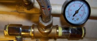
Therefore, before connecting the machine to the power system, it is better to check whether the parameters exactly match the network characteristics. This is the direct responsibility of the electrician. A three-phase network with a voltage of 380 V and a frequency of 50 Hz is required, grounding is required. Power cables (with a cross-section of at least 16 mm) are supplied to the equipment in a pipe or metal hose so as not to damage it during operation.
This CNC machine is the best that has been created today. It provides high-quality milling and engraving of the surfaces of parts, high precision processing of elements specified by the program (the G601 command to activate the step takes place only with precise positioning).
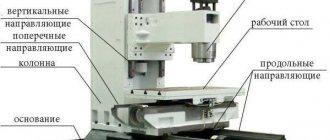
General requirements for drawing up electrical circuits
The electrical diagrams of a CNC machine (we are talking about the basic ones) usually depict each element of electrical equipment that participates in the technological process or controls its flow. It is customary to place power circuits on the left, indicating a place on the diagram with a thick line, and for control circuits, they are depicted on the right side as a thin line. When drawing up a diagram, it is conventionally assumed that all circuit elements are in the off state.
The elements have a schematic representation; they are given positional designations in the form of letters. In the case of one electric motor - M, and if there are several of them - M1, M2, M3 (in letter and numerical expression). If layout diagrams are built, everything related to electrical equipment is recorded on them (in a large-scale image). There is a thin line where there is space for connecting elements - wires and cables. Such diagrams are built, depicting specific components of the milling cutter; they are equipped with an electrical cabinet and a machine control panel.
As an example of the power equipment circuit of a numerically controlled device, one can imagine the following:
Modern electrical equipment has very complex circuit diagrams, and reading them is not always easy. And the situation is explained by the fact that in addition to electric motors, relays, starters and contactors, the machine includes many automatic means, computer equipment, and microelectronic equipment units. Different machines, in total, have a common electrical component and, at the same time, differ in the functional features of the blocks.
Tool clamp
To clamp the tool, you need to set the SA3 toggle switch (on the side panel) to the “Clamp” position and hold it with your hand. In this case, the KM4 starter is triggered, which supplies voltage to the motor of the tool clamping mechanism M4. The tool is being clamped. The clicking of the clutch in the clamping mechanism indicates the end of the tool clamping. The SQ10 microswitch with its contacts turns on the K5.1 starter, which becomes self-powered, turns off the M4 motor and prepares the spindle motor start circuit.
Unclamping the tool: set toggle switch SA3 to the “Unclamping” position and hold it with your hand. In this case, the KM5.1 starters are triggered. Starter KM5.3. supplies voltage to the M4 motor. The tool is spinning out. The end of the tool spin is controlled visually. Note: To avoid injury when opening the tool, the spindle start is blocked by the closing contacts K5. When the spindle is rotating, the opening of the tool is blocked by the opening contacts K5 in the M4 motor switching circuit. When clamping and unclenching the tool, in order to prevent the spindle from turning, it is necessary to set a low spindle speed (not higher than 400rpm)
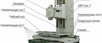
Specifications
The technical characteristics are somewhat similar to the previous model - 6P12. But some structural components are different. There is also a table of a different size. If in the model of the P12 series it was 1250 by 320 millimeters, then in the 6P13 it was increased to 1600 by 400 millimeters. Main technical characteristics of the unit:
- distance from the spindle to the surface - from 30 to 500 millimeters;
- to the axis of the spindle guide - 40 millimeters;
- manual movement in the longitudinal direction - 100 mm;
- transverse - 320 mm;
- vertical - 420 mm;
- mechanical movement in longitudinal - 1000 mm;
- transverse - 300 mm;
- vertical - 410 mm;
- maximum part weight - up to 300 kilograms;
- spindle speed - 31.5 to 1600 rpm;
- spindle speeds - 18 tpm;
- spindle end - class 3;
- it is possible to turn off the stop, block the feed and block the separate switching on of the feed;
- main electric motor power - 10 kW;
- cooling equipment - from 125 kW;
- feed drive power - 3 kW.
The weight of the machine model in question is 4200 kilograms (while in the previous model it was 3150 kg - increased by more than a thousand kilograms). Dimensions for installation: 2560 by 2260 by 2120 millimeters.