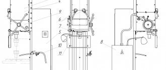
Kinematic diagram of milling machine 676P
Kinematic diagram of milling machine 676P
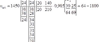
Main movement chain
From electric motor 1 with a power of 2.2 kW, the movement is transmitted to shaft 1 using V-belt transmission 2-3. From shaft 1 through the gearbox, rotation is transmitted to the drum gear 20, then to the shaft of the horizontal spindle VI.
The vertical spindle shaft VIII receives rotation from shaft VI through conical 22-23 and cylindrical 24-25 pairs.
Different positions of the gearbox gear blocks (7-6, 5-4, 14-15, 19-18) allow sixteen different speeds to be transmitted to the horizontal and vertical spindles.
Feed chain
All feeds of the machine (table in the vertical and longitudinal directions, spindle headstock in the transverse direction) are carried out mechanically and manually. In addition, fast travel is provided for all directions.
There is no independent feed drive in the machine. The feed mechanisms receive rotation from the main drive (shaft 1 of the gearbox) through the feed box. From the last shaft of the feedbox XIII, with the help of chain gears 50-62, 51-53, rotation is transmitted to the feed mechanisms of the table and spindle head.
Vertical feeds of the table are carried out as follows: shaft XVIII receives rotation from shaft XVII through a conical pair 63-64. To the vertical displacement screw XXIII, forward rotation is transmitted through gears 65-77, and reverse rotation through gears 74-75-76. Since the screw is fixed in the support, the table receives upward or downward movement.
Manual vertical movement is carried out by a flywheel sitting on shaft XXV, through conical pairs 80-81 and 78-79. Longitudinal feeds to the left and right are carried out by switching the clutch on shaft XIX, while rotation is transmitted through gears 66-65 and 74-75-67 to shaft XIX, through a bevel pair 68-69 to shaft XX, and then through gears 70-71 to the shaft screw XXI.
When the clutch on shaft XIV is switched, the headstock cross-feed mechanism imparts forward or reverse rotation to the nut 59 associated with the cross-feed screw, and the spindle head moves forward or backward.
The spindle head is manually moved by a flywheel using a conical pair 55-56 or 56-57.
Accelerated movements are carried out by coupling the coupling on shaft XVII with the coupling of the cylindrical wheel 49. Tables of the main movement and feed mechanisms are given in table. 5 and 6.
Design Features
The machine is recognized as widely versatile due to the presence of two spindles - horizontal and vertical, as well as a large number of different accessories for the machine. The base of the machine is made of cast iron and ensures the stability of the equipment while absorbing vibrations. The design features allow you to work with both small workpieces and parts up to 80 cm in length. At the same time, the machine is small in size and can be installed in a small workshop.
Spindle speed box
The gear transfer mechanism is located in front of the base of the box. When the handle is positioned as vertically as possible, discs with holes are separated. If the discs need to be brought back to the opposite position, the handle is lowered down.
Gearbox
To maintain the trajectory of the gears, the main gear is used, which is engaged when the gearbox reverse is engaged. In this case, the oil is served in very small portions.
Caliper
The caliper body is a dovetail mechanism. It is responsible for the movement of the main working area in two directions. Vertical advancement is carried out thanks to the guides that are available on the frame. Longitudinal movement is carried out due to horizontal guides. Control occurs due to the running shaft, and the latter receives movement from the gearbox.
Headstock
The spindle head mechanism is equipped with a cleaning rod. Thanks to it, the entire toolkit of the machine is clamped. To set the amount of automatic movement of the spindle head, there are intermediate supports.
Vertical head
The vertical head is mounted into the proboscis faceplate. The design has the ability to rotate 90° from the vertical axis. The operator can set the rotation angle to zero if necessary. In this case, the head must be secured with two pins using internal hexagon bolts. The splines transmit the rotational motion of the spindle tail, and double-row and roller bearings support the vertical spindle.
Corner horizontal table
This structure is cast from cast iron and bolted to the main work surface. For attachment there are T-shaped grooves - 3 pieces.
Vise
They can rotate around their own axis. They are an integral design of the machine and can be additionally mounted on both tables, which greatly facilitates the work.
Slotting head
The slotting head is built into a special round housing. This also includes a special trunk, which is built into the slotting and vertical heads.
Manual
Download the passport (operating manual) of the 676P machine
Today, it is quite difficult to find spare parts for the 676p milling machine, since its technical characteristics are somewhat inferior to those of modern models of milling machines. However, more recently, the equipment in question was installed in many workshops where small-scale and single-piece production was carried out. The instruction manual provides for the installation of additional equipment, for example, for performing slotting operations. This determines the versatility of the equipment. Other features of the model include the ability to rotate the spindle head by a certain degree within a set limit. The operating instructions provide for the use of several manual flywheels to move the table to the cutting tools and rotate the spindle head.
Main design elements
Kinematic diagram of the machine 676P
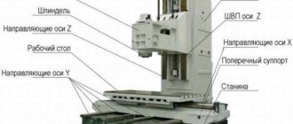
The design of the 676p universal milling machine is represented by the following main elements:
- Mains and electric pump switch. The electrical circuit provides for complete de-energization if necessary. In this case, the electrical circuit is made in a classic style, when all power is controlled through the “start” and “stop” buttons.
- Control is represented by flywheels, which are used to control the table, spindle and headstock.
- The passport determines the presence of a fairly large number of handles, which are responsible for controlling the main elements during the processing of parts.
- The main part of the structure is represented by a vertical frame, on the sides of which controls are located. At the top there is a headstock with a gearbox and spindle feed; at the front there is a table with several controls and a feed mechanism. The structure has a base, which, if necessary, can be rigidly fixed with bolts.
Electrical circuit of machine 676P
In general, we can say that the design of this model does not differ significantly from the design of many other models of the vertical milling group. The key feature of the 676p is the ability to rotate the spindle.
Specifications
Design features affect the main technical characteristics of the equipment:
- horizontal spindle rotation indicators – 50–1630 rpm;
- vertical spindle movement parameters – 63–2040 rpm;
- spindle speeds – 16;
- maximum advancement of the vertical spindle along the axis is 8 cm;
- distance from the axis of the horizontal spindle to the working surface – 8–46 cm;
- from the end of the vertical spindle to the working horizontal surface – 0–38 cm;
- maximum table travel along – 45 cm;
- vertically – 38 cm.
1 dial division is equal to 0.05 mm. The weight of the machine is slightly more than a ton (1050 kg).
Functionality check
This process begins with running the equipment at minimum speed, gradually increasing it to the maximum. The machine must operate in the main working gear of rotation for at least two hours, while the spindle supports cannot be heated above 50 degrees.
After checking the unit at idle speed, it is subjected to load. The milling cutter must operate at maximum cutting force in a short-term 25% overload mode. During normal operation in this mode, no vibration is observed and high processing accuracy is maintained.
Technical characteristics of the milling machine 676P
| Parameter name | 676P | 67K25PR |
| Main settings | ||
| Accuracy class according to GOST 8-82 | P | P |
| Dimensions of horizontal (corner) table, mm | 250 x 800 | 320 x 800 |
| Vertical table dimensions, mm | 250 x 630 | 250 x 630 |
| Maximum weight of the workpiece, kg | 100 | 350 |
| Distance from the axis of the horizontal spindle to the working surface of the horizontal table, mm | 80..460 | 45..595 |
| Distance from the end of the vertical spindle to the working surface of the horizontal table, mm | 0..380 | 10..490 |
| Overhang of the vertical spindle axis, mm | 125..375 | 165..485 |
| Maximum longitudinal stroke of the table (X), mm | 400 | 400 |
| Maximum stroke of the spindle head of the vertical spindle (Y), mm | 250 | 320 |
| Maximum vertical travel of the table (Z), mm | 380 | 450 |
| Vertical and horizontal spindles | ||
| Horizontal spindle rotation speed, rpm | 50..1630 | 40..2000 |
| Vertical spindle rotation speed, rpm | 63..2040 | 40..2000 |
| Number of spindle speeds | 16 | 18 |
| Limb division price, mm | 0,05 | 0,02 |
| Rule division price, mm | 1,0 | |
| Taper of horizontal and vertical spindles | Morse 4 | |
| Spindle head feed limits, mm/min | 13..395 | 10..1000 |
| Number of spindle head feeds | 16 | b/s |
| Accelerated speed of the spindle head, m/min | 0,9 | |
| Maximum headstock feed force, N | 9500 | |
| Maximum permissible torque on the horizontal/vertical spindle, Nm | 230/ 82 | |
| Tool clamp-release | Manual | Mechanism |
| Spindle braking | No | |
| Vertical milling head | ||
| Maximum axial movement of the vertical spindle, mm | 60 | 60 |
| Maximum angle of rotation of the vertical head in the vertical plane, degree | ±90 | ±90 |
| Weight of vertical milling head, kg | 70 | |
| Corner horizontal table | ||
| Number of table feeds in longitudinal and vertical direction | 16 | b/s |
| Limits of longitudinal and vertical table feeds (X. Y), mm/min | 13..395 | 10..1000 |
| Accelerated table travel in longitudinal and vertical directions, mm/min | 935 | 1800 |
| Maximum table feed force, N | 9500 | |
| Number of T-shaped slots | 5 | 5 |
| Weight of corner horizontal table | 105 | |
| Corner universal table | ||
| Dimensions of horizontal universal table, mm | 200 x 630 | 200 x 630 |
| Maximum rotation angle in the horizontal plane, degrees | ±20 | ±20 |
| Long side slope, degrees | ±45 | ±45 |
| Slope of the short side, degrees | ±30 | ±30 |
| Weight of corner horizontal table | 55 | |
| Round horizontal-vertical table | ||
| Table faceplate diameter, mm | 250 | 250 |
| Overall dimensions, mm | 345 x 330 x 110 | 338 x 485 x 140 |
| Round table weight | 60 | |
| Drive and electrical equipment of the machine | ||
| Number of electric motors on the machine | 2 | 4 |
| Main drive electric motor, kW | 2,2 | 3 |
| Feed drive electric motor, kW | — | 1,3 |
| Electric motor for lubrication and tool clamping, kW | — | 0,55 |
| Cooling pump drive electric motor, kW | 0,12 | 0,12 |
| Total power of electric motors, kW | 2,32 | 4,97 |
| Dimensions and weight of the machine | ||
| Machine dimensions (length x width x height), mm | 1282 x 1215 x 1780 | 1685 x 1655 x 1865 |
| Machine weight, kg | 910 | 1350 |
PURPOSE
The versatility of using SF 676 in large enterprises and small workshops is beyond doubt. Small production facilities, repair shops and auto repair shops use it to solve a huge number of technical problems related to vertical and horizontal milling, reaming, drilling and boring, thread cutting and many other additional operations. The technical data of the milling machine allows you to install it in a small room: a box, a small garage, and engage in private entrepreneurship by providing services for processing metals and plastics.