The easiest way to sharpen a kitchen knife is to use a regular sharpening stone. However, with this method it is difficult to maintain the correct sharpening angle.
If you sharpen “by eye,” especially if you have no experience, you can completely dull the blade.
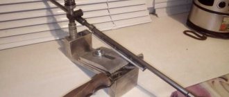
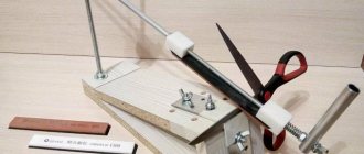
To sharpen a knife correctly, we recommend using a special device - a tabletop knife sharpener.
Similar devices are sold in hardware and construction stores.
But why spend money when you can make a knife sharpening device yourself from scrap materials?
In this article we will share with you budget ideas from home craftsmen. We recommend you read it.
What to do with dull knives?
If there are no problems with knives with replaceable blades (naturally, if these same blades are present), then a knife with a sharpened blade must be periodically sharpened. Typically, a special knife sharpening device is used for this.
Buying this now is not difficult. But not everyone prefers this solution to the problem. And the point here is not only the considerable cost of such devices. High-quality sharpeners cost a lot of money.
Many craftsmen will get great pleasure from a machine designed for sharpening knives, made by themselves. Although, even using an ordinary “bare” block, of course, you can sharpen knives with your own hands, but in order to sharpen a knife efficiently using only a whetstone, also known as a “block”, you need to have a certain skill and “steady” hands, because you will need to maintain the sharpening angle identical along the entire cutting edge, and this is not the easiest task. A special sharpener for knives is designed to make it easier, be it factory-made or made with your own hands.
But just to speed up sharpening, any sharpener, both factory-made and home-made, will help.
Why do you need a sharpener?
A living relic of our days is the Finnish hunting knife. Not a gangster Finnish knife, sometimes of a bizarre shape, but a Finnish-type hunting knife, on the left in the figure. Traditional hunting knives (center and left) are similar in shape, but the difference between them is very large.
Finnish knife and classic hunting knives
The blade of a Finnish knife is forged from cast iron, which can be smelted right in your yard from swamp ore in a furnace-furnace, without resorting to the blast furnace process, puddling, and other methods of converting cast iron into iron and steel.
The viscosity of crinkly iron is excellent; it is very difficult to break a blade made from it. But the hardness is also low, somewhere around HRS55, the knife becomes dull quite quickly.
Finnish hunters did not care about this: a blade of such hardness can be sharpened (sharpened) by beating on many natural stones, and there were always enough smoothed moraine boulders in Fennoscandia.
They sharpen a knife by beating it in much the same way as beating a scythe, only the whetstone is motionless and the blade is moved. First, they pull it along the whetstone with the butt away from you, then they turn it over and pull it with the butt towards you.
The position of the cutting edge (CR) on the whetstone is always dragging; quick movements: shirk-shirk! During each movement, you need to keep the contact patch of the blade with the touchstone (see below), but the requirements for maintaining the angle of inclination are not so strict.
Learning to sharpen a knife by beating is not very difficult, and with some skill you can create a smoothly running profile on the blade, see below. However, the Finnish knife is, in general, a dead end in the evolution of a cutting tool, surviving in special natural conditions.
A good knife has never been cheap, and in extreme situations, the durability of the blade, combined with the toughness of the blade, became vital factors. Therefore, even in ancient times, they learned to harden knife blades from the surface and cement them: the core remained viscous, not brittle, and a hard, red-hot crust formed on the outside, see next. rice.:
Structure of a knife blade with surface hardening and carburization
It is still possible to sharpen a knife with a cemented blade, but you need a skill that is not given to everyone. And the abrasive is already needed from a special type of stone - lithographic grunstein slate. There is little of it in nature; Grünstein is still considered a strategic raw material.
There is no artificial grenstein and it is not expected.
It’s as easy as shelling pears to ruin a cemented knife with inept beating - a little somewhere the cementation bark will be stripped down to raw metal (this is not visible to the eye), the knife will only have to be thrown away, the blade will immediately become dull and begin to crumble.
Note: if you have an antique scythe whetstone of a slightly greenish color lying around somewhere, do not throw it away, it is a valuable rarity.
Service knives do not require the same durability and toughness as hunting and hiking knives, and they should cost much less. As a result, special steels and powder metallurgy are widely used in the production of utility knives.
The blade of an “eternal” kitchen knife is structured like a rodent’s incisor: in longitudinal layers, the hardness of which decreases from the core outward.
In any case, you have to sharpen the knife less often, but chipping is definitely ruled out - the blade immediately becomes discolored.
How to sharpen a knife?
For these reasons, push-pull sharpening technology (push-pull sharpening or push-pull sharpening technique) was invented long ago:
- The blade is pushed along the touchstone away from you with a twist, holding the butt towards you, the position of the RK is advancing (scraping);
- Then, without lifting the blade from the whetstone, they pull it with the butt towards you with a turn in the opposite direction, the position of the RK is dragging;
- The blade is turned over and repeat steps. 1 and 2;
- pp. 1-3 are repeated, reducing the pressure in each cycle, until the burr formed on the RA disappears (does not stick together).
Note: when they say or write “the hangnail will go away”, etc., this is incorrect. Metalheads have a slang word for it: "zausavka"; for electricians - “switch off”. But in Russian, a burr and a switch are masculine.
Push-pull sharpening protects the blade, but requires high skill from the operator, because During the sharpening process, a number of conditions must be continuously and precisely observed, see also fig. below:
- Maintain the angle of inclination of the blade to the whetstone, smoothly changing it in accordance with the curvature of the wheel.
- Make sure that the tangent to the generatrix of the blade and the transverse axis of the contact spot of the wheel with the touchstone coincide.
- Also ensure that the axis of the contact patch is always perpendicular to the longitudinal axis of the touchstone.
- Smoothly change the pressure on the blade as the area of the contact patch changes.
It is very difficult to meet all these conditions at the same time, completely symmetrically on the forward and reverse stroke of the blade along the touchstone, and a modern knife, as mentioned above, can be damaged by improper sharpening. Any household device for sharpening knives is designed to relieve the sharpener from continuous monitoring of at least part of these conditions.
Manual knife sharpening
Note: for successful push-pull sharpening, the length of the whetstone (see below) must be at least 2 times the length of the knife blade from the handle to the tip.
Sharpening profiles
The profile of a knife blade is linked to the properties of the material and the structure of the blade, as well as to the properties of the materials for which the tool is intended to process. Sharpening on a simple blunt wedge (item 1 in Fig.
) gives a stable but rough blade: the cutting resistance is high, and the knife tears quite viscous materials. Sharp wedge (pos.
2) quickly dulls or chips; on viscous and/or fibrous materials, the cutting resistance may be greater than with a blunt wedge due to the friction of what is being cut on the blade.
Knife blade sharpening profiles
Ideal in all respects is the ogival (smoothly sloping) profile, pos. 3. Experts are still arguing which generator is better - an involute, a hyperbola or an exponential.
But one thing is certain - making an ogival blade in production conditions is difficult and expensive, and it is impossible to direct it yourself. Therefore, ogival sharpened knives are used only in special equipment, e.g.
microtomes - biological devices for obtaining the thinnest tissue sections.
For disposable blades, e.g. safety razor blades, faceted sharpening is used, pos. 4, i.e. The ogive generatrix, as mathematicians say, is approximated by straight segments. The number of sharpening edges is indicated in the certificate or on the manufacturer’s website. For thick, coarse bristles, 3-4-sided bristles are better; for delicate hair not on the face - 8-sided. The 6-sided one is considered universal.
Corner ?
The sharpening angle is always given in half the value ?, because Many tools and, for example, bayonet knives are sharpened on one side. For knives for various purposes, the angle is ? maintained in the following. within:
The use of a manual knife sharpener such as Lansky-Metabo, pos. 1 in Fig. The diagram of its device is given in pos. 2, and the procedure for use is in pos. 3.
The disadvantage of the Lansky-Metabo sharpener is the instability of the sharpening angle along the length of the blade: a rod with a touchstone is driven along it. The offset of the touch point is constantly changing, because it describes an arc of a circle, and the blade has a different configuration. Resp. The angle also “floats”.
Therefore, the Lansky-Metabo sharpener is used primarily for sharpening camping and hunting knives with a relatively short blade.
Knife sharpener type Lansky-Metabo
However, this disadvantage can be turned into an advantage if the blade is clamped in the terminals with the root part A (at the handle) and the tip slightly turned away from you, pos. 4.
Then the sharpening angle at the root of the blade will be greatest, which is optimal for processing hard materials or using the knife as a cleaver.
This is how they work in such cases, so that the outer arm of the arm-blade lever is shorter.
Towards the middle of blade B, the sharpening angle will gradually decrease and reach a minimum at the bend of its generatrix B1, which is convenient for fine work. Then towards the tip the B angle will increase again, making the tip more resistant to drilling, chiselling/impacting and punching (piercing).
What are the differences between abrasive stones?
Sharpening stones come in a variety of shapes, bar sizes, and grain sizes. The optimal size of the bar is considered to be one in which its length exceeds the length of the blade of the knife being sharpened by at least one and a half times. This allows you to work with such a bar much more comfortably than with a bar that does not meet this simple requirement.
As mentioned earlier, sharpening stones can have not only different sizes, but also very different grain sizes. There are five main levels of grain size for such bars:
- Grain size 200-300 Extra coarse. In English called Extra coarse. Such bars are not used for sharpening tool blades and knives in particular;
- Grain size 300-350 Coarse grain. In English called Coarse. With the help of such bars, damaged or very dull blades are sharpened;
- Grain size 400-500 Medium grain. In English called Medium. You can do without such a block in the household;
- Grain size 600-700 Fine grain. Called Fine in English, these whetstones are the most popular for sharpening tool blades in the home workshop.
- Grain size 1000-1200 Very fine. In English called Ultra fine. These bars are used for final processing of blades that need to be brought to a shine. Such bars can be used as a tool for a homemade knife sharpener.
Technical data and characteristics of the 3A64 machine
| Parameter name | 3A64 | 3A64m | 3A64d |
| Main settings | |||
| Accuracy class according to GOST 8-82 | P | ||
| Largest diameter of the installed product, mm | 250 | 250 | 250 |
| Maximum length of the product installed in the centers, mm | 650 | 650 | 600 |
| Distance between the axis of the grinding wheel and the line of centers in the horizontal plane, mm | 70..300 | 70..300 | 70..300 |
| Distance between the axis of the grinding wheel and the line of centers in the vertical plane, mm | 55..150 | 55..150 | 55..150 |
| Center height, mm | 125 | ||
| Machine work table | |||
| Dimensions of the working surface of the table according to GOST 6569-75 (length x width), mm | 134 x 920 | 134 x 920 | 140 x 900 |
| Maximum longitudinal/transverse manual movement of the table, mm | 400/ 230 | 400/ 230 | 400/ 230 |
| Transverse movement of the table by one division of the dial, mm | 0,02 | 0,02 | 0,01 |
| Transverse movement of the table per one revolution of the dial, mm | 2 | 2 | |
| Transverse table movement by one fine feed division, mm | No | No | 0,0025 |
| Table rotation angle in the horizontal plane, degrees | ±45° | ±45° | ±45° |
| Grinding head (column) | |||
| Maximum vertical movement of the headstock, mm | 205 | 205 | 205 |
| Price for dividing the vertical movement feed dial, mm | 0,02 | 0,02 | 0,002 |
| Headstock rotation angle in the horizontal plane, degrees | 270° | 270° | 350° |
| Grinding head | |||
| Grinding wheel speed with stepwise regulation, rpm | 3730, 5600 | 2000, 2800, 4020, 5820 | 2240, 3150, 4500, 6300 |
| End of grinding spindle | 1:20 20 mm | 1:20 20 mm | Morse 3 |
| The largest diameter of the installed grinding wheel, mm | 175 | 175 | 175 |
| Maximum width of the grinding wheel, mm | 15 | 15 | |
| Maximum height of the cup grinding wheel, mm | 45 | 45 | |
| Electrical equipment and machine drive | |||
| Number of electric motors on the machine | 1 | 2 | 4 |
| Grinding wheel spindle drive electric motor, kW (rpm) | 0,65 (2800) | 0,75; 1,0 | 0,75; 1,0 |
| Product drive electric motor, kW | 0,25 | ||
| Cooling pump electric motor, kW | 0,125 | ||
| Vacuum cleaner electric motor, kW | 0,6 | ||
| Total installed power of all electric motors, kW | |||
| type of supply current | 50Hz, 380/220V | 50Hz, 380/220V | 50Hz, 380/220V |
| Dimensions and weight of the machine | |||
| Machine dimensions, mm | 1700 x 1460 x 1600 | 1700 x 1460 x 1605 | 1700 x 1460 x 1605 |
| Machine weight, kg | 1000 | 1040 | 1100 |
- Universal sharpening machine 3A64. Care and Maintenance Manual, 1947
- Dibner L.G., Tsofin E.E. Sharpening machines and semi-automatic machines, 1978
- Demyanovsky K.I., Dunaev V.D. Sharpening wood cutting tools, 1965
- Kudryashov A.A. Tool production machines, 1968
- Lisova A.I. Design, adjustment and operation of metal-cutting machines, 1971
- Menitsky I.D. Universal sharpening machines, 1968
- Paley M. M. Technology of production of metal-cutting tools, 1982
- Rozhkov D.S. Design, setup and operation of equipment for sharpening wood-cutting tools, 1978
Bibliography:
Related Links. Additional Information
- Classification and main characteristics of the grinding group
- Repair, restoration and modernization of grinding machines: the American approach
- Cylindrical grinding. Processing on cylindrical grinding machines. Grinding Methods
- Setting up a cylindrical grinding machine when installing parts in centers
- CNC grinding machines
- Marking of grinding wheels
- Testing and checking metal-cutting machines for accuracy
- Grinding machines. Market of grinding machines in Russia
- Manufacturers of grinding machines
- Directory of grinding machines
- Manufacturers of metal-cutting machines
- Articles on the topic
Home About the company News Articles Price list Contacts Reference information Interesting video KPO woodworking machines Manufacturers
Why do knives get dull?
In order to ensure long and comfortable work with a knife after sharpening, first of all try to answer the question, “Why do knives become dull?” Why is it necessary to sharpen the knife again some time after sharpening, and sometimes to completely sharpen the knife again?
The reason for the loss of sharpness by the cutting edge of any tool is this: when working, the cutting edge of a knife or any other tool is exposed to the smallest abrasive particles of the material being cut.
Such particles are found in any material, be it stone, wood, or food.
Even soft vegetables and fruits contain such particles. There may just be more or less of them, but they will definitely be there. Their size, sharpness and quantity only determine the speed at which the instrument will become dull.
Fixation device
The second important part of the tool rest is the clamping bar. It can be made from 2 parts.
L-shaped plank measuring 150x180 mm, the width of the shelves is 50 mm (top);
A rectangle-shaped strike plate measuring 50x100 mm (bottom).
When making a clamping bar, the machine operator performs the following actions:
Places the bottom bar on the far edge of the top bar;
Makes 2 holes in the center and retreats 25 mm from the edges of the part, connects the parts through the holes with two 8 mm bolts;
Screws in 8 mm bolts on 2 sides. In such a situation, the head of the nearest bolt is located near the top bar;
Welds the bolt heads to the plates and grinds them in advance until roundness is formed;
Yes, the inclined board retreats 40 mm from the edge and draws a line with a thicknesser;
Makes one 8 mm 25 mm gap at the bottom and top edges;
Using markings, he connects the edges of the slots and uses a jigsaw to make a cut with an allowance. Use a file to expand the groove to a width of 8.5 mm;
It fastens the planks using a groove that is in the board; the top bolt is tightened with a nut and thus firmly fastens the plank.
Then tightens connection 2 with nut;
When pressing the bottom bar (in the niche of the base), screw a wing nut onto the second bolt.
Sharpening angle, what is it?
So, since it is impossible to stop the process of dulling the cutting edge, then at least try to slow it down, and for this you need to sharpen your tool very well. Earlier in this article you have already come across such a concept as the sharpening angle of the cutting edge. And now more about it.
Blade sharpening angles can vary greatly. From an angle of about 10 degrees for razors and scalpels, to an angle of about 50 degrees for various Machete-type knives.
Sharpening angle control
When adjusting the sharpening angle, the mechanic performs the following actions:
Throw a large washer onto the pin, which is located in the block of the machine base, and tighten the nut.
The rod does not rotate in the foot; the block for adjusting the sharpening angle is made from a small carbolite block, the dimensions of which are 20x40x80 mm.
15 mm from the block edge, drill a 20 mm end on both sides, widen the gap to 9 mm, then make a thread inside;
He steps back 50 mm from the axis of the new slot and drills another one in the flat part of the workpiece - 90 degrees to the previous one. Such a slot has a diameter of 14 mm. In such a situation, the mechanic strongly flares the hole using a round rasp;
Screws the block onto the stud - sets the desired height of the eye without using fixing screws;
Secures the block on both sides with M10 hex nuts.
What could cause such a significant difference?
The fact is that the sharpening angle depends on what materials the blade is supposed to cut. The smaller the angle, the softer the materials should be and vice versa.
The fact is that a blade with a small sharpening angle will not only be easier to cut, but will also become dull more easily. That is why there is not and cannot be a single universal sharpening angle.
Note!
Do-it-yourself compressor: selection of materials and tools for assembly at home + step-by-step instructions for making and assembling yourselfHomemade products for the garage with your own hands: options for products for arranging a garage, detailed diagrams and drawings for creating with your own hands
Do-it-yourself press - design features, choice of manufacturing materials. Step-by-step instructions for making it yourself + simple diagrams and drawings
After reading this article, you will not only learn how to properly sharpen a knife so that it can serve you for a long time until the next sharpening, but also answer your question about how to make such sharpening easier.
To facilitate the correct sharpening of knives, a lot of different tools have been invented, from the simplest devices to the most exotic ones, at a quick glance at which it is not only unclear how to work with them, but it is also difficult to figure out what it is in general.
Basic mistakes
As it may seem at first glance, sharpening is simple, but if you delve into the process itself, you will notice a fairly large number of different nuances. Most people make simple mistakes when sharpening knives, which leads to uneven sharpening or damage to the knife. Common mistakes when sharpening:
- The cutting edge was not sharpened . As a result, small burrs form on the sides, which temporarily give sharpness to the blade, and after working with the knife for a short time, the blade again becomes dull. To prevent this problem, you should carefully sharpen both edges, and then, as you sharpen, use sandpaper or a wheel of different grits.
- Presence of paint, oil, dirt on the tip . The bottom line is that during turning, fat, dirt, oil and other components mix with grinding abrasives and lead to scratches and microchips of the blade. After such sharpening, the blade quickly becomes dull.
- Pressure plays an important role . You need to remember one simple rule: sharpness does not depend on the force used, but on the duration of sharpening. Excessively strong pressure leads to chipping of microparticles from the blade and poor sharpening.
- Wrong choice of angle . The angle may vary depending on the grade of steel and the purpose of the tool. For home kitchen knives it is 20 - 25 degrees. For other types of blades that will have to withstand heavy loads and work with hard materials, the angle will be 40 degrees.
What knives can be sharpened?
Not all blades can be sharpened at home, but only blades made from not very hard materials. So, if the hardness of the material from which the blade is made exceeds 55 units on the Rockwell scale (55HRC), then it will not be possible to sharpen it with any tool available to most people. But most of the knives produced now are made of fairly soft materials and such knives are not at all difficult to sharpen.
True, their service life between sharpenings is not long at all.
But no matter what metal the knife is made of, sooner or later it will still have to be sharpened. The only exceptions to this rule are knives with replaceable blades and ceramic knives that cannot be sharpened at all. Thus, a knife sharpening device must be universal, that is, it must be able to sharpen various blades with different sharpening angles.
Note!
Do-it-yourself winch: classification, manufacturing materials, description of work stages + instructions for DIY construction- Do-it-yourself clamp - step-by-step production and description of options for using a clamp
DIY knife | A step-by-step description of how and from what materials to make a homemade knife
Therefore, when creating a device for sharpening knives, it is necessary to provide for the possibility of sharpening blades with different angles, and this is the most difficult task both at the design stage and during the manufacture of such a device.
General layout
The machine is designed with vertical movement of the grinding head, with longitudinal and transverse movement of the table and a lower location of the spindle drive.
All machine mechanisms are mounted inside and on the upper plane of the frame.
The machine is equipped with a local lighting lamp.
Depending on the nature of the work, the workplace can be either in front of the machine, or on the left or right, according to which the controls are located.
bed
The bed is a box-shaped cast iron casting that carries guides and transverse movement of the caliper on the upper plane. The grinding wheel drive electric motor located inside the frame is serviced through a window in the side wall, closed with a lid. Starting and protective electrical equipment is placed in a niche covered with a lid. The front wall is slightly lowered for ease of cleaning sludge from the upper wall of the frame; The upper wall is even lower in machines designed to work with coolant.
Universal sharpening machine 3a64
Support device of machine 3a64
The machine (Fig. II, 73) has the following main components: frame 1, support device 2 and grinding head 3.
Bed 1 is a box-shaped cast iron, on the upper horizontal plane of which guides for the lower slide are machined.
The support device (Fig. II, 74) has a lower slide 17, a longitudinal table 15 and a rotary table 18. The lower slide 17 moves along the frame guides using a screw 14 and a nut 13 when one of the handwheels 10 rotates. Duplicating this handwheel is intended to provide convenience machine maintenance. The longitudinal table 15 moves along the guides 12 of the lower slide, made in the form of rolling guides. Fast movement is carried out by the handle 16 through the rack and pinion wheel 24 and rack 25, slow movement by the handle 19, attached to the body of the planetary mechanism, the gear ratio of which is 1/10. To prevent lateral play of the longitudinal table, two ball bearings 32 and 35 are mounted on the axes at the ends of the lower slide, which cover the ridge 26 of the longitudinal slide on both sides. To be able to adjust the gap between the ridge 26 and the roller ball bearings 32 and 35, the axes of the bearings 35 are fixed in the swing arms 34 and springs 33 are pressed against the side wall of the ridge 26.
On the front wall of the table there is a T-shaped groove for attaching adjustable stops 20, which serve to limit the longitudinal movement of the table in contact with the stop 23, fixedly mounted on the lower slide.
The rotary table 18 is centered on the longitudinal table by axle 11. The angular installation of the rotary table is carried out using handle 31, screw 30 and nut 28 fixed on the longitudinal table, strip 27 and pin 29 installed in the rotary table. The angular displacement is measured on a scale on bar 27 with a division value corresponding to a taper of 0.01. In addition, there is a 22 degree scale mounted on a longitudinal table 15.
The turntable is secured in the installed position with nut 21.
The grinding head assembly 3 (Fig. II, 73) consists of an outer sleeve 5 and a column 4, to the upper plane of which the grinding spindle housing is attached. Devices for setting centers, for internal grinding, etc. are attached to the upper processed area of the spindle body. The grinding head is moved vertically using a handwheel through a worm gear 7, a rack wheel and a rack 6 attached to the sleeve 5. To install it at the required angle, release nut 9, use handle 8 to turn column 4 in sleeve 5 and tighten nut 9 again.
The angle of rotation of the head is measured according to the scale marked on the sleeve 5.
Rotation of the spindle is transmitted through a belt drive from an electric motor with a power of 0.65 kW, which is mounted on the sleeve using a square. The spindle can rotate at 3730 or 5600 rpm.
The scope of use of the universal sharpening machine is expanded by the accessories attached to it for external, internal, and flat circular grinding; for sharpening backed disc cutters, milling heads, hobs, radial thread dies, taps, long reamers, twist drills, countersinks and other tools; universal head, front and rear center headstocks, clamp, device for setting centers. The fixtures, mounted on the top ground surface of the turntable, are secured to it using T-head bolts.
As can be seen from this list of accessories, on the machine mod. ZA64 can be used to perform, in addition to sharpening operations, external, internal and flat grinding.
Lifting mechanism
Column lifting mechanism of sharpening machine 3A64
The lifting mechanism (Fig. 3) of the grinding head is installed on the upper wall of the frame between the guides. The neck 7 is attached to the frame with bolts 20 after alignment and setting the position of its axis perpendicular to the plane of the table with adjusting screws 19. In the neck hole, a sleeve 4 moves with a rack 8, which engages with a gear 14. The additional purpose of the rack 8 is to prevent the sleeve from turning. For rigid fastening of the sleeve, the upper part of the neck is cut and when tightening the nut 18, it covers the sleeve like a terminal clamp. In the lower part of the neck 7, located inside the frame, there is a bracket 11 with a worm gear 9, 10, driven into rotation by flywheels 16. The worm shaft is held against axial movement by a sleeve 15. The axis of the worm wheel 10 is the shank of the rack and pinion gear 14. The amount of vertical movement is measured with precision 0.02 mm is produced according to the scales of the installation rings 17. The protruding part of the sleeve is protected from dust by a fabric cover 6. A column 5 is supported by a flange on the upper end of the sleeve, carrying a grinding head and a bracket 13 with an electric motor and allowing the spindle to be rotated in a horizontal plane. The angle of rotation is indicated by scale 2. The column is clamped by the brake pin 3, which is pressed by the rocker arm of the grinding head 1.
To tension the drive belt of the grinding wheel spindle, screws 12 are loosened and bracket 13 is lowered.
Caliper
Sharpening machine support 3a64
The table support (Fig. 4) consists of mutually perpendicular lower and upper slides with corresponding movement mechanisms. The lower slide 1 moves along the guides in the transverse direction using a lead screw 9. The hinge nut 10 with its cylindrical end is installed in the socket of the upper wall of the frame. Verniers 8 and 15 allow you to determine the feed rate with an accuracy of 0.02 mm. The upper slide 2 moves along roller guides 23, which are chains 25 assembled from roller bushings 24, the diameters of which differ from each other by no more than 0.002 mm.
In the roller guides (Fig. 4), the roller bushings 24 are replaced by free rollers placed in special separators, which made it possible to replace worn out rollers without much difficulty.
To prevent lateral shift in the lower slide, two ball bearings 14 are installed on rigid axes, to which the guide longitudinal protrusion 22 of the slide 2 is pressed by springs 13 by means of ball bearings 12 mounted on the levers. Thus, the ball bearings 14 perceive the action of the cutting force and facilitate the longitudinal movement of the tool with the table. The longitudinal movement of the slide 2 is ensured by handles 11 or a planetary mechanism 17, the gears of which can engage with a rack 7 mounted on the longitudinal protrusion of the slide. Stops 18 prevent the slide from tipping over in the extreme positions of the table.
On the front wall of the slide 2, stops 19 move in the T-shaped groove, limiting the longitudinal movement of the table. The stops are double-sided with one rigid and one spring-loaded finger; they can be easily swapped depending on working conditions - “with soft” or “hard” stops. They mostly work with a “soft” stop, since at the end of the table’s stroke the spring compresses and, gently stopping the table, gives it a push in the opposite direction. The movement of the stops is limited by screws 3 and 6 located in the groove to prevent accidental shift of the slide 2 above the permissible table stroke. The table 23 with a T-shaped groove for fastening and orienting devices can be rotated relative to the longitudinal axis of the slide 2. The rotation angle up to 5° is measured on a scale of 5, above 5° - on a scale 4. Accurate
The table is installed using a screw 21, which moves the scale 5, which can be connected to the table using a lock 20.
Planetary mechanism 17 (Fig. 4) is designed for slow manual movement of the table for various grinding jobs, especially for flat and cylindrical external and internal grinding.
The mechanism is turned on and off by introducing the rack and pinion gear into engagement with the rack or disengaging it by means of axial movement of the roller with button 16.
Grinding head
Grinding head of sharpening machine 3a64
The grinding head (Fig. 5) is installed on the column of the lifting mechanism and consists of a housing 8, in which a spindle 1 with conical journals for installing flanges with grinding wheels is mounted on two pairs of high-precision radial ball bearings. Each pair of bearings is installed in cups 7. The preload of the bearings is adjusted by nuts 4 and locknuts 6. Hole 2 in the spindle serves to keep the spindle from turning (using a steel rod inserted through the hole in the cover 9, covered by a shield 10) while tightening the nut 5 at changing the grinding wheel. The drive flat belt pulleys are made directly on the spindle, and to move the belt from one pulley to another, it is necessary to remove the cover 9. When changing the belt, the spindle along with the cups is removed from the housing, for which the clamping screws 11 are unscrewed and the housing, cut along the entire length, is opened using screws 12. Screws 3 are intended for installing grinding wheel covers.
As mentioned above, the column, after setting the spindle axis to the required angle, is clamped by the rocker arm 13, which is released or tightened by the nut 14 located on the handle 15.
What properties should a sharpener have?
So, before you make a device for sharpening knives with your own hands, you need to think about its design. And to do this, you need to answer the question: what properties should a knife sharpener have:
First, any device for sharpening knives must securely fix the knife, preventing it from falling out, but without damaging the blade material.
Secondly, a homemade knife sharpener must ensure that the block is held at a strictly defined angle, which is necessary for sharpening the entire cutting edge at a constant angle.
Third, the most difficult and perhaps the most important, a sharpening machine for knives, both self-made and factory-made, should allow changing the angle of installation of the sharpening stone; this is necessary to ensure sharpening of various tools and will even allow sharpening of stepped knives.
Note!
DIY vices: simple and reliable homemade vices from A to Z (190 photos)Do-it-yourself vibrating table - selection of materials, components and assemblies for a vibrating table with a step-by-step manufacturing description
Do-it-yourself grain crusher - operating principle, types and features of creating a device for processing grain crops
Device for sharpening from wooden blocks
A simple device for sharpening knives is a tool consisting of a pair of wooden slats and a pair of abrasive bars with the same geometric dimensions.
Wooden slats should be thoroughly sanded with abrasive sandpaper. Then, after applying auxiliary markings, depending on the sharpening angle of the knife, make cuts to a depth of 15 mm. Insert sanding blocks into the resulting holes so that each groove matches, then secure them with bolts. To give the sharpening device greater stability, the lower part of the surface can be padded with a piece of rubber.
The types of devices for sharpening cutting tools are different and each master will be able to choose the manual machine that will fully satisfy his needs.
What will we make it from?
The next question to consider is.
The materials from which you will make it.
To create such a device you will need the following materials:
- A sheet of thick plywood (can be replaced with a sheet of chipboard) 16 mm thick;
- Self-tapping screws 50-70 mm long; (it is better to use furniture format);
- A drill corresponding in diameter and length to your self-tapping screws or conformation;
- M8 hairpin of appropriate length (approximately 70 cm);
- Aluminum plate (at least 5 mm thick);
- M8 bolts with nuts (it is advisable to use wing nuts, although you can also use regular nuts, but keep in mind that then, with each sharpening, you will have to use a wrench, and this, you will agree, is not very convenient);
- You will also need a small block of textolite or ebonite to create a movable connection between the stud and the frame, which can be adjusted in height (if necessary, it can be replaced with a block made of hard wood, for example, it could be oak, beech or hornbeam);
- Of course, you will also need abrasive stones of various grain sizes;
- You will also need a powerful neodymium magnet (“you can get” such a magnet from an old computer hard drive that has become unnecessary).
Base
When making a sharpening machine at home, you can use various parts. In particular, you can use laminated box plywood 12 mm thick, which was previously used to create radio equipment housings.
When constructing a machine at home, a household member performs the following actions:
Selects a base for such an installation, which must weigh at least 5 kg. Otherwise, it will be impossible to sharpen chopping devices and tools on the machine. Therefore, in the manufacture of such equipment, the tenant uses various steel angles measuring 20x20 mm;
Next, 2 parts are cut out of plywood with a jigsaw, which have a trapezoidal shape, the base is 170 by 60 mm, and the height is 230 mm. When cutting, the mechanic makes an allowance of 0.7 mm for sharpening the ends: they end up straight and fit according to the markings;
Installs 3 parts between the inclined walls on the sides - an inclined surface made of plywood with dimensions of 230 x 150 mm.
In such a situation, the trapezoidal sides are located laterally on a rectangular surface.
The result is a base - a wedge. In such a situation, a protrusion of an inclined surface measuring 40 mm is formed in the front part;
Then, along the side wall ends, the mechanic marks 2 lines with a thicknesser. At the same time, it retreats by half the thickness of the plywood;
Next, he drills 3 holes in the boards to connect the parts of the structure with screws;
Drills the ends of the inclined surface and connects the base parts for a while;
At the back of the structure, the mechanic connects the side walls using a 60x60 mm block, which is attached to the end with two screws on both sides; — makes a 10 mm gap in the block.
In such a situation, it retreats 50 mm from the center - 25 mm from the edge. To maintain a vertical position, first drill with a thin drill from 2 edges, and then expand;
Then, at the top and bottom, two threaded fittings are screwed into the gap, and in the fittings - a 10 mm pin, the length of which is 250 mm.
If the threads do not match the studs, the lower fitting is adjusted.
What are we going to do?
The tools you will need are: a drill, a drill of a suitable length and diameter, a screwdriver with bits suitable for your screws or format. Instead of a screwdriver with suitable bits, you can also use a screwdriver (but this will be more difficult).
Any tool for cutting metal (a hacksaw or an angle grinder equipped with a cutting wheel).
Using replaceable blocks and making a carriage
When making a sharpening carriage, the machine operator performs the following actions:
Welds 30 cm M10 threaded rods with a smooth rod whose thickness is 10 mm;
Uses 2 solid bars 50x80 mm and the thickness is 20 mm. In all blocks, in the center and on top, 20 mm is retreated from the edge, and then a gap is made 10 mm wide;
Screws a wing nut onto the rod, then a large washer and 2 bars, then a nut and washer;
Clamps rectangular sharpening stones between the stones or makes several replaceable sharpening stones.
As a timber base, the machine operator uses a rectangular tube from a profile or a piece of cornice, the width of which is 50 mm;
He sands the flat machine part and cleans it of grease, and glues strips of sandpaper with a grain size of up to 1200 grit using Super Moment glue.
The sandpaper should have a fabric base, and on one of the blocks you need to glue a strip of suede to apply polish to the blades.
How will we do it?
Having asked the question “how to make a knife sharpener?” First of all, let’s find drawings for our future knife sharpener, which we will make with our own hands, and to do this, enter the following query into the search bar: “device for sharpening knives drawings.”
In response to such a request, any search engine will return a large number of suitable search results. Choose the one you like.
Having cut the plywood in any convenient way into parts for our future frame, we drill them at the points of attachment to each other, and then fasten them with self-tapping screws or conformat to each other.
On the frame we fix, using a bolt, an aluminum plate pre-processed according to the drawing (it will serve as a clamp for the knife being sharpened).
Next, we attach a vertical section of the pin to the frame and firmly fix a “cracker” on it. It consists of two parts made of an ebonite block (the Cracker is a very important part, it determines the angle at which the abrasive bar and the blade being sharpened will come into contact).
Now let's create a mount for the abrasive stone: for it we use the remaining section of the pin. Two blocks of ebonite or other similar material and two nuts.
3A64 Kinematic diagram of the sharpening machine
Kinematic diagram of the sharpening machine 3A64
Description of the kinematic diagram of the sharpening machine
Kinematic chains perform the following working and installation movements:
- Rotation of the spindle of the grinding head
- Longitudinal movement of the table
- Transverse movement of the table support
- Vertical column movement
- Rotation of the product drive head spindle
The grinding wheel spindle is driven by a single-speed AC electric motor N = 0.75/kW, n = 2860 rpm, which in combination with two-stage pulleys provides two spindle rotation speeds. The belt is tensioned by moving the bracket with the electric motor installed on it using a rack-gear transmission z = 14.
Transverse movement of the table is carried out using a lead screw with a thread pitch t = 2 mm. The longitudinal movement of the table is carried out manually using retractable handles, which engage with the table rail using gears 2=14. Slow movement of the table is carried out by a planetary mechanism, the gear ratio of which is 1:7.
The vertical movement of the grinding head is carried out by one of the flywheels through a worm gear 2=1; 2 = 45 and rack and pinion 2 = 15.
What did we get?
Having assembled the design according to the drawing, you will receive the simplest device for sharpening knives, however, despite its simplicity, this device will allow you to sharpen knives and any other blades quite efficiently.
In order to understand how to use such a device, just enter “video knife” in any search engine.
Did you manage to sharpen the knife? Hooray! You have successfully made a DIY sharpening machine.
We should not forget that any sharpening machine, even if it is made by hand, requires strict adherence to the rules and safety requirements!!!
Information about the manufacturer of the universal sharpening machine 3A64
The manufacturer of the 3A64 universal sharpening machine is the Vitebsk Sharpening Machine Plant, Visas , founded in 1897.
The 3A64 machine was also produced at the Leningrad Machine Tool Plant named after Ilyich
.
Machines produced by the Vitebsk sharpening machine plant, Visas
- 3A64
- universal sharpening machine, Ø 250 x 650 - 3A64M
- universal sharpening machine, Ø 250 x 650 - 3A64D
- universal sharpening machine, Ø 250 x 600 - 3A662
- semi-automatic grinding machine for hob cutters, Ø 200 x 280 - 3B642
- universal sharpening machine with hydraulic drive, Ø 250 x 630 - 3B642
- universal sharpening machine, Ø 250 x 630 - 3D641E
universal sharpening machine with hydraulic drive, Ø 200 x 400 - 3D642E
- universal sharpening machine with hydraulic drive, Ø 250 x 630 - 3E642
- universal sharpening machine, Ø 250 x 630 - 3E642E
- universal sharpening machine with hydraulic drive, Ø 250 x 500 - 3M642
- universal sharpening machine, Ø 250 x 500 - 3D692
- universal grinding machine for circular saws, semi-automatic, Ø 275..1430 - 3E692
- universal grinding machine for circular saws, semi-automatic, Ø 250..1430 - 3662
— grinding machine for hob cutters, semi-automatic, Ø 125 x 200 - VZ-318, VZ-318E
- universal sharpening machine, Ø 200 x 500 - VZ-818, VZ-818E
- universal sharpening machine, Ø 200 x 500 - VZ-319
- universal tabletop sharpening machine, Ø 100 x 200 - BDS-4
- combined wood cutting machine - BDS-5
- combined wood cutting machine
Photo of a DIY knife sharpener
Manual sharpening of jointer knives
Source housechief.ru
Knives need to be checked for integrity. The branded blade should have a slight longitudinal bend - this is necessary for a tighter clamp when rotating. If you notice small chips (they are possible when a nail or screw is missed in the lumber), then this cannot be corrected with a hand tool - you will need machine processing. But when even a slight crack appears anywhere in the canvas, it is dangerous to work with it - the metal can crack further and injure your hands and face with fragments.
Now you need to prepare the knives for sharpening. First, thoroughly wipe them with white spirit to eliminate any grease stains, not only on the cone of the blade, but also on the main part. Grease should not get on either the sandpaper abrasive or the slot in the wooden template. Are you wondering where fat comes from? My answer is that when removing the knife, you can get it dirty with lubricants.
Source housechief.ru
Unfortunately, our hands are not automated and the load on the template may be uneven, but there is a way to avoid uneven sharpening. After you clamp the blades in the device, mark a stripe on the tip of the blade with a marker. Based on the abrasion of the paint, it will be clear whether the jointing knives are being sharpened correctly or whether there is still a misalignment.
Take three strips of sandpaper with different fractions (it is better to use a zero grade at the finish), but there is another important point - all three abrasive strips must be on a perfectly flat plane so that the blade is sharpened evenly. To do this, they can be glued to thick glass or to a proven tabletop.
A few basic rules for sharpening (using the example of twist drills for metal):
For a better perception of the material, let’s remember the structure of the drill.
- Do not press the tip against the sandpaper for more than 2-3 seconds at a time. The metal heats up and the so-called “tempering” occurs, that is, deprivation of hardening. Accordingly, the necessary hardness of the metal is lost. The first sign is the presence of temperature discoloration on the edge.
- For drills with a diameter of up to 4 mm: each time the sandpaper plane touches the drill, the drill is held in one position: rotation around its axis is not allowed. For larger diameters, the sharpening geometry is slightly different.
- On twist drills, only the back surface of the cutting part is sharpened.
- The cutting edge should be directed towards the rotation of the sharpener (for mechanical sharpening).
- The main angle (2φ in the illustration) depends on the type of material being processed.
