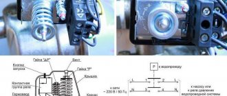
Typical diagram for connecting a motor via a magnetic starter
This wiring diagram for a three-phase motor should be given the closest attention. It is most common in all industrial equipment produced until about the 2000s. And in new Chinese machines and other simple equipment with 2-3 engines they are still used to this day.
An electrician who does not know it is like a surgeon who cannot distinguish an artery from a vein; as a lawyer who does not know Article 1 of the Constitution of the Russian Federation; like a dancer who does not distinguish a waltz from a tectonic.
In this circuit, three phases go to the motor not through the machine, but through the starter. And the starter is turned on/off using the “ Start ” and “ Stop ” buttons, which can be placed on the control panel through 3 wires of any length.
An example of such a circuit is in the article about restoring the circuit of a hydraulic press, see the last circuit in the article, KM0 starter.
5. Diagram of connecting the motor through a starter with start-stop buttons
Here, power to the control circuit comes from phase L1 (wire 1 ) through a normally closed (NC) “Stop” button (wire 2 ).
Often in such schemes the starter does not turn on due to the fact that the contacts of this button “burn out”.
The diagram does not show a control circuit breaker; it is placed in series with the “Stop” button, the rating is several amperes.
If you now press the “Start” button, the power circuit of the coil of the KM electromagnetic starter will close (wire 3
), its contacts will close, and three phases will go to the motor. But in such schemes, in addition to three “power” contacts, the starter has one more additional contact. It is called a “locking” or “self-latching contact”.
Not to be confused with blocking in reverse circuits, see below.
The “Self-Pickup” contacts are physically located on the same mount with the power contacts of the contactor, and operate simultaneously.
When the electromagnetic starter is turned on by pressing the SB1 “Start” button, the self-retaining contact also closes. And if it is closed, then even if the “Start” button is pressed, the power circuit of the starter coil will still remain closed. And the engine will continue to run until the “Stop” button is pressed.
It often happens in such schemes that the starter does not “self-retain.” It's about that fourth contact.
How to install a button yourself instead of the ignition switch with aliexpress
If you nevertheless set out to equip your iron horse with such a device, it’s time to get acquainted with the features of its installation. At the moment, there are several ways to install the start-stop button. Let's consider the most common and fairly simple method.
To bring this idea to life, we will need a minimum set of components from Aliexpress, which includes:
- four-pin relays;
- connecting wires;
- diode;
- the actual start-stop button.
Once all the components have been found, it’s time to start installing the system itself.
At this stage, it is important to adhere to a certain sequence of actions. This approach will save you from all sorts of unwanted surprises, which in the future can result in serious problems
The installation algorithm involves the following steps:
- the positive terminal of the battery should be connected to the positive contact of the relay;
- the enabling “+” relay is also connected to the battery;
- the negative terminal is mounted to the ground of the car;
- the control contacts of the load relay are connected to 12V;
- the control negative output is connected to the corresponding output of the button;
- the enabling positive signal remains unconnected.
The presented installation diagram differs from all others in its ease of implementation and should not cause difficulties even for a novice car enthusiast.
What is included in the package, tools and consumables
It would not be superfluous to mention the completeness of the device in question. Due to the fact that currently there is an abundance of all kinds of analogues and modifications
given device, it is important to choose the most suitable one
It often happens that, due to his lack of awareness, a car enthusiast, ordering a “start-stop” button on various trading platforms, falls for the tricks of scammers or simply unscrupulous sellers
That is why it is important to know which consumables should be included with this device.
So, the complete set of delivery assumes the presence of:
- the “start-stop” button itself;
- control module;
- connecting wires with connectors.
However, the standard package does not allow you to assemble a working circuit for this device. To do this you will need to buy several more relays.
Connection diagram
To connect the device to the car, you must follow a specific connection diagram. We bring to your attention one of these schemes with a detailed explanation of the operation of key elements.
Here's another diagram, maybe it will be easier to navigate.
How to connect the device correctly
When installing a button, it is extremely important to avoid making mistakes when connecting one or another node. To do this, you must be guided by the above diagram
It is also worth noting that one diagram will not be enough to carry out the button installation procedure. In this case we are talking about various kinds of accompanying actions. Let's look at them in more detail.
Before implementing the planned project, you will have to perform some actions, namely:
- remove the ignition switch;
- remove the steering wheel lock mechanism;
- disconnect the underwater leads;
- remove the immobilizer antenna;
- install the button in the most suitable place for yourself;
- connect underwater wires.
After carrying out the above actions, the stage of checking the system for operability follows. If you follow the instructions supplied with the device, such a procedure should not cause serious difficulties.
Video on connecting the Start-Stop button
To get acquainted with the installation of the presented device, we invite you to watch a video dedicated to the topic in question.
In it you will find useful information that will help save you from all sorts of troubles at all stages of system assembly.
Connection diagram for a starter with a thermal relay
In the circuit above, I left out the thermal protection for the sake of simplicity of the circuit. In practice, a thermal relay of the RTL type is necessarily used (at least, this was accepted before 2000 for us and until 1990 for “them”)
6. Connection diagram of the starter with buttons and thermal relay
As soon as the motor current increases above the set one (due to overload, phase loss), the contacts of the thermal relay RT1 open and the power circuit of the electromagnetic starter coil breaks.
Thus, the thermal relay acts as a “Stop” button, and is in the same circuit, in series. Where to put it is not particularly important, it can be in the section of the L1 - 1 circuit, if it is convenient for installation.
However, a thermal relay does not protect against short circuits to the housing and between phases. Therefore, in such schemes a circuit breaker must be installed, as shown in Diagram 7:
7. Connection diagram of the starter with automatic buttons and thermal relay. PRACTICAL SCHEME
Attention! The control circuit (the circuit through which the KM starter coil is powered) must be protected by a circuit breaker with a current of no more than 10A. This circuit breaker is not shown in the diagram. Thanks to attentive readers!)
The current of the QF motor circuit breaker does not need to be selected as carefully as in scheme 3, since the RTL can handle the thermal overload. Enough so that it protects the suitable wires from overheating.
Example. The motor is 1.5 kW, the current in each phase is 3A, the thermal relay current is 3.5 A. The motor power wires can be taken 1.5 mm2. They hold current up to 16A. And it seems like the machine can be set to 16A? However, there is no need to act clumsily. It’s better to put something in between – 6 or 10A.
Specifications
Dimensions, weight and packaging
| Dimensions, mm (L×H×D) | 88×166×140 |
| Weight, g | 850 |
| Individual packing | Eat |
| Quantity per package, pcs/pack | 20 |
Specifications, description, delivery package and country of production are subject to change by the manufacturer without prior notice. All information on the site is for informational purposes only and under no circumstances constitutes a public offer as defined by the provisions of Article 437 of the Civil Code of the Russian Federation.
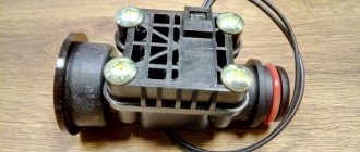
Designed for remote starting and stopping of three-phase asynchronous electric motors with a squirrel-cage rotor, as well as for switching thermal loads and lighting networks. Protects equipment from overloads of unacceptable duration and from currents arising when one of the phases is broken.
Rated operating current for various application categories is based on 380 VAC.
The starter/contactor is irreversible, with a degree of protection IP54, with 1c auxiliary circuit contacts, with alternating current control circuit, with a relay current setting range of 7-10 A.
You can buy the product “Magnetic starter / contactor PML-1210-10 380V/AC-3 3z+1z with a thermal relay with a relay reset button in a protective shell IP54” of the PML-1210 series in a shell manufactured by TEXENERGO with the article number “te00120708” online on the Internet -store or by phone: .
You can also make a purchase in the Electron retail chain stores.
Connection diagram of the magnetic starter from the controller
Over the past 10 years, controllers have been widely used in new industrial automation. The starter coils are also switched on from the controller outputs. And in this case, to protect against short circuits and thermal overheating, motor connection diagram number 8 is used:
8. Connection diagram for a starter controlled by a controller. PRACTICAL SCHEME
In the diagram, QF is an automatic motor, or motor protection circuit breaker, as in diagram 4. I just depicted it in a modern way. In this case, the starter connection diagram is “hidden” in the dotted line. There is a controller there that controls everything and turns on the engine according to the program embedded in it.
When the engine is overloaded, the automatic motor turns it off and opens its additional (fourth, signal) contact. This is only necessary to “inform” the controller about an accident. Often this contact simply enters the control circuit and stops the entire machine.
Connection diagram for reversing magnetic starter
In fact, these are two magnetic starters, combined electrically and mechanically, more details below.
Reversible motor control
A reversing starter is needed when it is necessary for the motor to rotate alternately in both directions.
Right rotation (used most often) - when the engine rotates clockwise when looking at its rear. Left rotation - counterclockwise.
Changing the direction of rotation is realized in a well-known way - any two phases are swapped. Look at the motor reverse circuit diagram below:
9. Connection diagram for a 220V reversible magnetic starter with button control. PRACTICAL SCHEME
When the KM1 starter is turned on, it will be “right” rotation. When KM2 is turned on, the first and third phases change places, the engine will spin “to the left”. Turning on the starters KM1 and KM2 is realized by different buttons “ Start forward ” and “ Start reverse ”, turning off is done by one common button “ Stop ”, as in circuits without reverse.
Pay close attention to the triangle between the power contacts KM1 and KM2. It means “foolproof.” It may happen that for some reason both starters turn on at once. A short circuit will occur between phases L1 and L3. You can say, “So what, we have a QF automatic engine, it will save us!” What if it doesn’t save you? And while he is saving, the contacts of the starters will burn out!
Therefore, the reversing starter must have mechanical protection against simultaneous activation of its two halves. And if it consists of two separate starters, a special mechanical interlock is placed between them.
Now look at the contacts KM2.4 and KM1.4, located in the power circuits of the starter coils. This is electrical protection from the same fool . For example, if KM1 is turned on, its NC contact KM1.4 is open, and if our fool, with all his foolishness, presses both “Start” buttons at once, nothing will happen - the engine will obey the button that was pressed earlier.
Mechanical and electrical protection must always be present in the connection diagram of the reversing starter; they complement each other. Not installing one or the other is bad manners among electricians .
Important! If there is even a minimal probability of the engine rotating in the wrong direction, be sure to install a phase control relay! Here is an example - how we burned a screw compressor worth several thousand euros due to the fact that the phases were mixed up when connecting.
To implement electrical interlocking of simultaneous switching on and self-retaining, each starter requires, in addition to power ones, one more NC (blocking) and NO (self-retaining). But since, as a rule, there is no fifth contact in starters, you have to install an additional one. contact. For example, for a PML type starter, the PKI prefix is used. And if, as in scheme 8, a controller is used, self-retaining is not needed, and one NC contact for each direction of rotation is sufficient.
Reversible hydraulic control
And here is an example of reverse valve control, from an article about a hydraulic press:
Electrical circuit for hydraulic control
The fact that relays are used should not be confusing. In fact, a contactor and a relay are one device, the only difference is in the design and parameters.
In fact, the circuit repeats the circuit for the engine, only instead of the “Stop” button there are two limit switches, and buttons SB1, SB2 - with additional NC blocking contacts. A detailed description of how the circuit works is here.
The operation of the reversing starter is also described in detail in the article about connecting the generator to the home network.
Cost indicators
The cost of Russian push-button posts is quite low and depends primarily on the number of buttons, category of placement and climatic design. Devices in a metal case are slightly more expensive than analogues installed in a plastic case.
For example, the price of two-button devices “PKE-222-2” is in the range of 250.0...280.0 rubles. A similar device with a mushroom-shaped “Stop” button will cost a little more – 380.0 rubles.
The price of one-button posts does not exceed 150 rubles. The six-button telpher remote control “PKT-60” costs 300.0 rubles. A device with a similar number of buttons and electrical parameters, equipped with a key (“foolproof”), will cost 200.0 rubles more.
Difference between 220V and 380V starters
Coils of magnetic starters for operation in 380V networks can be 220 and 380 Volts without any special modifications to the circuit. In all the diagrams given in this article, electromagnetic starters have a coil for a voltage of 220 V. What to do if you get a starter not for 220 V, but for 380 V?
Everything is very simple - you need to connect the lower (according to the diagram) terminal of the 380V starter coil not to zero (N), but to L2 or L3. This circuit is even more preferable, since the entire circuit with a 380V starter can be assembled without a zero at all. Three phases come in, and three phases go out to the engine, not counting the control.
Why is everything so difficult
This question initially haunted me, but everything is complicated only at first glance. If you do all the work step by step, in accordance with the instructions, it will disappear by itself. As already mentioned, the main difficulties were created, one might say, intentionally. After all, all you had to do was purchase a more advanced push-button station at any electrical store, and most of the work simply lost its relevance. But the fact that I took such a problematic path also has its advantages - all options were considered at zero cost. Everything I needed was in the garage. But now I have the opportunity to use a low-cost sharpening machine. The only costs are the purchase of an emery grinding wheel and payment of electricity bills, which cannot be called large.