For testing and subsequent use, a cheap Chinese sensor was selected, which uses optical technology of a combination of a single infrared emitter and receiver to achieve non-contact determination of liquid level. The sensor itself has no electronic interface circuitry - it simply contains one infrared LED and one phototransistor inside.
Optical level sensor design
It can be installed in any direction and installation can only take a few minutes as there is no calibration procedure. It is recommended to install the sensor on the side or bottom of the liquid reservoir for best results. Please note that performance will be adversely affected by other reflective surfaces in the immediate vicinity of the sensor head.
↑Measurement method
There are a great variety of level gauges on sale. But somehow it didn’t even occur to me to look for something ready-made, it’s not sporty, it’s not “our thing.” So I decided to make the device myself. Moreover, it was not enough for me to know the upper and lower levels, I wanted to know exactly how many liters were in the tank. Of course, for this purpose - monitoring the water level in the tank, this information is redundant, but it’s more reliable. Since my current work is related to ultrasonic flaw detection, the choice of measurement method was not difficult. There are many offers of ultrasonic distance sensors on the market. There are expensive ones with a digital interface and for a long distance, there are cheap ones with a simpler interface for a shorter distance. The choice fell on the simplest and cheapest sensor HC-SR04
.
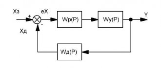
Electrical diagram for connecting the module
Typical electrical circuit for operation from a 5 V power supply.
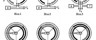
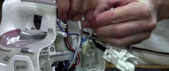
The cable protrudes from the sealed sensor assembly and has a small 4-pin (2-pair) wire connector at the end. One pair of these wires is connected to the LED (light emitter) inside, and the other is connected to the phototransistor (light receiver). Here is a typical connection diagram for an optical liquid level sensor.
Although the diagram above gives a general idea of the connections, we recommend checking the color code of the wires before testing, as incorrect connections may damage the electronics.
How to connect a water sensor to Arduino
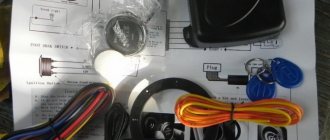
For this lesson we will need:
- Arduino Uno / Arduino Nano / Arduino Mega board;
- bread board;
- water sensor;
- 1 LED and 220 Ohm resistor;
- male-male and male-female wires.
Diagram for connecting a water sensor to Arduino
Before connecting a water leakage sensor to the Arduino board, you should write a sketch. Open the Arduino IDE program and you will see a sketch where the void setup() and void loop() procedures are already written. First, let's set the water variable using the int operator. We will use a variable to store data in memory and assign it the value received from the water sensor.
Go to Menu Bar - Tools - Port Monitor
In the void setup() procedure, we specify the operating mode of the analog port as an input - the pinMode(AO,INPUT) command and connect the port monitor using Serial.begin(9600). Next, in the void loop() procedure, we get the value from the analog port using the command water = analogRead(A0); and pass the value to the Arduino IDE port monitor Serial.println(water); and pause for our convenience.
Sketch for a water sensor
int water; // assign a name to the values from analog input A0 void setup() { pinMode(A0, INPUT); // connect a sensor to input A0 (eng. “intput”) Serial.begin(9600); // connect the port monitor } void loop() { water = analogRead(A0); // the variable "water" is in the range from 0 to 1023 Serial.println(water); // display the sensor value on the monitor delay(1000); // delay one second }
Explanations for the code:
- in the first line we assigned the name water to the int variable to store the values from input A0, the values of water can only take an integer.
After uploading the sketch, you will be able to get data from the sensor on the port monitor. To do this, go to the Arduino IDE in Menu Bar - Tools - Port Monitor. Ctrl + Shift + M to open . After we have found out the readings of the sensor when it is moistened, we can add to the sketch the function of automatically turning on the LED when a certain value is exceeded.
Sketch for water sensor and Arduino LED
int water; // assign a name to the values from the analog input A0 void setup() // procedure setup { pinMode(12, OUTPUT); // pin 12 with the LED will be the output (English “output”) pinMode(A0, INPUT); // connect a sensor to input A0 (eng. “intput”) Serial.begin(9600); // connect the port monitor } void loop() // procedure loop { water = analogRead(A0); // the variable “water” is in the range from 0 to 1023 if (water > 100) { digitalWrite(12, HIGH); } // turn on the LED if (water < 100) { digitalWrite(12, LOW); } // turn off the LED Serial.println(water); // display the sensor value on the monitor delay(1000); // delay one second }
Operating principle of an optical level sensor
The sensor contains an infrared LED and a phototransistor. Because the light from the LED is transmitted to the optical head, the phototransistor receives zero light (or less light) when the sensor is immersed in the liquid - the passing light beam will be refracted. If there is no liquid, the transmitted light will be returned to the phototransistor directly through the optical head. Therefore, if the sensor detects the liquid level, it issues a low level signal.
Useful: Adjusting the rotation and reverse of the motor from the washing machine
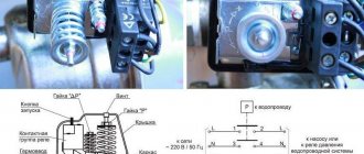
The figure below shows several options for installing the sensor in various containers.
By looking at the output signal with a multimeter, you can see a logic high signal in the "dry state" and a logic low signal in the "wet state". The following circuit allows you to use the sensor output to directly control an indicator or even a standard electromagnetic relay.
Here you may need to change the value of R1 (minimum 390 ohms) and R2 (maximum 10 kohms) to get acceptable results. The BS170 element (T1) is a small signal N-channel, 500 mA, 60 V MOSFET available in a TO-92 package, but not logic level.
Calibration
To get accurate readings from your water level sensor, it is recommended that you first calibrate it for the specific type of water you plan to monitor.
As you know, pure water does not conduct electricity. In fact, it is minerals and impurities that make it conductive. So your sensor may be more or less sensitive depending on the type of water you use.
Before you start monitoring data or running any event handlers, you need to see what readings you're actually getting from your sensor.
Using the sketch above, note what values your sensor produces when it is completely dry, when it is partially submerged, and when it is completely submerged.
For example, using the same circuit as above, you will see values similar to the following in the serial port monitor:
- when sensor is dry: 0;
- when it is partially immersed in water: ~420;
- when it is completely immersed: ~520.
Figure 6 - Water Level Sensor Calibration
This test may require some trial and error. Once you have good control over these readings, you can use them as thresholds if you intend to initiate any action. In the next example, we're going to do just that.
Level meter circuit upgrade
This time it's all based on the popular CD4049UB hexadecimal inverting buffer and converter (IC1). The chip has standardized symmetrical output characteristics, a wide operating voltage range from 3 V to 18 V and is recommended for devices that do not require high current or voltage conversion.
Here, the CD4049UB-based circuit provides single-point liquid level sensing via a TTL-compatible push-pull output, but more optical level sensors can be added to implement your own expandable, multi-channel, microcontroller-compatible liquid level sensing module.
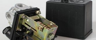
How does a relay work?
In the initial state, until voltage is applied to the relay winding, the armature, under the influence of the return spring, is at some distance from the core.
When voltage is applied, current immediately begins to flow in the relay winding and its magnetic field magnetizes the core, which, overcoming the force of the return spring, attracts the armature. At this moment, the contacts attached to the anchor, moving, close or open with the fixed contacts.
After turning off the voltage, the current in the winding disappears, the core is demagnetized, and the spring returns the armature and relay contacts to their original position.
Test results and real work
Testing has found that there are no false alarms, even when installed inside a small transparent water tank in bright daylight. If you immerse the tip of the sensor (the clear prism) in water, it works as expected.
In general, this optical level sensor has no moving parts and is ideal for measuring extreme water levels. It produces an output signal that can indicate the presence or absence of liquid. A compact and inexpensive optical liquid level sensor like this is a good choice, especially where measurement accuracy is not important.
Hardware overview
This sensor contains a series of ten open copper traces, five of which are power and five are sensitive.
These tracks are interleaved so that between every two supply tracks there is one sensing track.
Usually these paths are not connected to each other, but when immersed they are connected by water.
Figure 1 – Water level sensor
There is a power indicator on the board that lights up when power is applied to the board.
Testing the project's operation
Once the hardware of the project is ready, connect the Arduino board to your computer (laptop) and upload the program code to the Arduino board. Open the Serial Communication Monitor window at 9600 baud. Place an object in front of the ultrasonic sensor, the calculated distance to it will be displayed in the serial communication monitor window and on the LCD screen.
You can watch the project in more detail in the video at the end of the article.