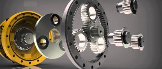
Rotary compressor with cam rotors
This design option is used when it is necessary to transfer a large volume of substance in a minimum period. Among the features we note:
- The moving parts do not touch. This is why the likelihood of severe wear is reduced.
- There is no need to add oil, which greatly simplifies the maintenance process.
- Larger devices have an electric motor that is connected directly to the main element. Smaller versions are equipped with a V-belt drive.
There are quite a large number of varieties of such devices. The main elements can be called:
- Frame.
- Rotor.
- Timing gears.
- Sealing gaskets.
- Bearings.
The operating principle of the device can be described as follows:
- The rotors are not in mesh during operation.
- The gas inside is not compressed.
- It is possible to install moving elements on parallel screws.
- The cams are not touching.
- Bearings and distribution parts are lubricated during operation.
The scope of application of such devices is very extensive. An example is various industrial installations, as well as equipment for applying paints and varnishes.
Operating principle of a gear compressor
The screw block is an important element of the rotary compressor design. The service life of such an element is approximately 15-20 years. It is worth considering that the compressor rotor has a special shape, due to which certain operational characteristics are ensured.
The principle of operation of the device determines that at the time of air supply there is no vibration or strong noise. The main part of the rotary compressor does not have elements that operate by reciprocating motion. Therefore, the structure can be installed in the immediate place of operation.
The operating principle is characterized by the following features:
- The body is used as the basis of the structure.
- Inside the mechanism there are two gears that are meshed.
- The mechanism has an inlet and outlet pipe.
Refers to rotary compressors devices that have gears that are meshed. It is worth considering that for significant wear of the main parts, a lubricant is added. In addition, there are models that also work without lubrication.
How an air compressor works and works
The design of the air compression unit is determined by the type of construction. Compressors are piston, rotary and membrane. The most widely used are piston air units, in which air is compressed in a cylinder due to the reciprocating movements of the piston inside it.
Device diagram
The design of an air piston compressor is quite simple. Its main element is the compressor head. Its design is similar to the cylinder of an internal combustion engine (ICE). Below is a diagram of the piston unit, which clearly shows the structure of the latter.
The compressor unit includes the following elements.
- Cylinder. This is the volume in which air is compressed.
- Piston. By reciprocating movements it sucks air into the cylinder or compresses it.
- Piston rings. Installed on the piston and designed to increase compression.
- Connecting rod. Connects the piston to the crankshaft, transmitting reciprocating movements to it.
- Crankshaft. Thanks to its design, it allows the connecting rod to move up and down.
- Inlet and discharge valves. Designed for inlet and outlet of air from the cylinder. But compressor valves are different from internal combustion engine valves. They are made in the form of plates pressed by a spring. The opening of the valves is not forced, as in an internal combustion engine, but due to the pressure difference in the cylinder.
To reduce the friction force between the piston rings and the cylinder, oil is supplied to the compressor head. But in this case, the air leaving the compressor contains lubricant impurities. To eliminate them, a separator is installed on the piston apparatus, in which the mixture is separated into oil and air.
If special purity of compressed air is required, for example, in medicine or electronics production, then the design of the piston unit does not imply the use of oil. In such devices, the piston rings are made of polymers, and graphite lubricant is used to reduce the friction force.
The crankshaft is driven by an electric motor via a belt or direct drive. With a belt drive, the design of the device includes 2 pulleys, one of which is installed on the motor shaft, and the second on the shaft of the piston block. The second pulley is equipped with blades for cooling the unit. In the case of direct drive, the shafts of the motor and the piston unit are connected directly and are on the same axis.
Also, the design of a piston compressor includes another very important element - a receiver, which is a metal container. It is designed to eliminate pulsations of air leaving the piston block and works as a storage tank.
Thanks to the receiver, you can maintain the pressure at the same level and distribute air evenly. For safety, an emergency relief valve is installed on the receiver, which is triggered when the pressure in the tank rises to critical values.
In order for the compressor to operate in automatic mode, a pressure switch (pressostat) is installed on it. When the pressure in the receiver reaches the required values, the relay opens the contact and the engine stops. And vice versa, when the pressure in the receiver decreases to the set lower limit, the pressure switch closes the contacts and the unit resumes operation.
Operating principle
The operating principle of a piston compressor can be described as follows.
- When the engine starts, the crankshaft begins to rotate, transmitting reciprocating movements through the connecting rod to the piston.
- The piston, moving downwards, creates a vacuum in the cylinder, under the influence of which the intake valve opens. Due to the difference in air pressure, it begins to be sucked into the cylinder. But before entering the compression chamber, the air passes through a cleaning filter.
- Next, the piston begins to move upward. In this case, both valves are in a closed state. At the moment of compression, the pressure in the cylinder begins to increase, and when it reaches a certain level, the exhaust valve opens.
- After opening the exhaust valve, compressed air is directed to the receiver.
- When a certain pressure is reached in the receiver, the pressure switch is activated and air compression is suspended.
- When the pressure in the receiver drops to the set values, the pressure switch starts the engine again.
Oil-free screw compressor maintenance
First of all, it should be noted that rotary compressors of any type, and oil-free ones in the first place, are not intended for very dusty rooms.
Abrasive particles entering the screw block damage the surfaces of the rotors and disrupt the geometry of their shapes. As a result, the rotating screws begin to touch, which causes increased friction, scoring and seizing.
Many manufacturers apply special protective coatings to rotors to protect against wear and corrosion.
Foreign manufacturers were the first to do this. Treating the rotors with special polymer compounds made it possible not only to reduce the likelihood of their contact with the subsequent formation of scuffing, but also to reduce the cost of precision machining of surfaces.
Due to the inclusion of tiny particles of solid lubricants, polymer coatings have high antifriction properties, which allows them to effectively reduce friction and prevent the formation of scuffing.
Over time, factory coatings wear out, and in order to solve the issue of restoring them, it is necessary to use ready-made antifriction materials. Previously, such compounds were exclusively imported, but today their production has been established in our country.
The Russian company Modengi has developed a series of anti-friction solid lubricant coatings for screw compressors, which can be used both in the production and repair of rotors.
MODENGY coatings are applied to the surfaces of parts in a layer of up to 100 microns, then, after running-in, the thickness decreases by 2-2.5 times and becomes optimal.
The polymer matrix of the coating firmly holds particles of solid lubricants in its cells, which perform anti-friction and extreme pressure functions.
MODENGY 1007 is produced on the basis of graphite, therefore it has a characteristic gray-black color. The coating works stably at temperatures of -50…+350 °C, and has a load-bearing capacity of 1300 MPa (SRV test).
The bearing capacity of MODENGY 1014 is even higher, it is 2700 MPa. The operating temperature range of the coating with molybdenum disulfide and polytetrafluoroethylene is -75...+255 °C. The composition has high anti-corrosion properties - >672 hours (salt fog test).
MODENGY 1066 with graphite and molybdenum disulfide can withstand temperatures from -70 to +315 °C. The coating also has anti-corrosion properties (>300 h in salt fog) and high load-bearing capacity (9900 H according to the Falex method).
Before applying the coating, the remains of old lubricants, dust and other contaminants are removed from the rotor surfaces. To completely clean and degrease the screw pair, use the MODENGY Special Cleaner-Activator. Its use promotes high adhesion of the future coating and guarantees its long service life.
Antifriction compounds are applied to the rotors in several layers, then the parts are heated to polymerize the coatings. All materials are cured when heated above +200 °C for 20-40 minutes (the exact time depends on the type of coating).
Rotors coated with MODENGY do not require re-treatment in the future - a correctly applied protective layer does not wear off, as it does not allow the screw surfaces to come into contact.
Main parts of a screw compressor
A rotary compressor consists of several main elements, which ensure the supply of medium under high pressure. Considering the design features, we note:
- A pair of worm geared rotors, one of which is driving, the second is driven.
- The housing can be manufactured in a variety of ways and is characterized by high tightness.
- The volume of the structure depends on the shape of the rotor, as well as their dimensions.
A wide variety of rotor profiles are found in production. In general, we can say that the main operational characteristics largely depend on this.
In conclusion, we note that rotary compressors are one of the most common today. When choosing, attention is paid to the technical condition, type of materials used in manufacturing, working volume and many other points.
Source
Compressor performance
Compressor performance is usually expressed in units of volume of gas compressed per unit of time (m3/min, m3/hour). Productivity is usually calculated based on indicators normalized to normal conditions. In this case, the productivity of the inlet and outlet is distinguished; these values are almost equal at a small pressure difference between the inlet and outlet, but with a large difference, for example, in piston compressors, the output productivity can fall by more than 2 times at the same speed compared to input capacity measured at zero pressure difference between inlet and outlet. Compressors are called booster if the pressure of the suction gas significantly exceeds atmospheric pressure.
Difference between oil and oil-free compressors
There is another classification, which is based on the use of a lubricant in the mechanism.
Oil compressors
Oil in compressors is used to lubricate parts - this protects them from wear. A side effect of using oil is that it is present in the air at the outlet. Although modern compressors use filters to separate oil from air, microscopic oil particles are still present in the air. This is unacceptable in the pharmaceuticals, food industry and some other areas. The need for completely clean air led to the creation of oil-free compressors.
At the same time, oil compressors are more reliable and have a long service life, since the engine and bearings wear out more slowly. When caring for them, you need to periodically check the oil level - if it is low, you will need to change the oil in the air compressor.
Oil-free compressors
The operating principle of oil-free compressors is not much different from oil-based ones. However, in this case, work occurs in a “dry” chamber, without lubrication. This leads to increased wear of parts and high operating temperatures. To extend the life of such units, manufacturers try to use materials with a low coefficient of friction and even inject water into the working chamber. The service life of oil-free models still remains lower than that of oil-based ones, but the air they compress is clean. For such equipment to work properly, it requires a good cooling system.
What is a screw compressor: device and principle of operation
This is a device for compressing and supplying air or other gases. Let's move on to the purpose of the parts.
Components
In general this is:
- suction filter - passes through itself and cleans the air in front of the compression unit;
- inlet valve – switches the compressor operating mode load/idle;
- electric motor – drives the rotors of the compression unit;
- screw block - two parallel oriented rotors (one convex, the other concave);
- drive – engages the screw pair with the engine, also responsible for rotation at a given speed;
- oil cooler – reduces the oil temperature to preset values, preventing overheating;
- oil separator - a special reservoir (tank) that separates oil from compressed air;
- thermostat - changes the direction of oil movement: small circle - directly into the screw block; large circle - through the cooler;
- oil filter - cleans the oil before feeding it into the screw unit;
- relay and safety valve - protect against damage by triggering when pressure suddenly increases;
- pipelines - connect all departments of the system, ensuring the passage of the oil-air mixture, oil and compressed air;
- fan – facilitates air intake and also performs the function of general cooling;
- control unit – monitors the operation of the compressor in normal mode, alerts in case of an accident and adjusts parameters;
- aftercooler – reduces the temperature of the medium before releasing it from the equipment.
The operating principle of a screw compressor in detail
Step by step it looks like this:
- the engine starts the rotors, which, in compliance with the schedule, rotate towards each other;
- as a result of this movement, atmospheric air is sucked through a filter, in which it is cleaned of mechanical impurities;
- in the screw block, air is mixed with oil, compressed and enters the oil tank;
- in the oil tank and separator, the compressed air is separated from the oil and flows through the aftercooler to the outlet of the installation, and the oil, after cooling, flows back into the screw block through the oil filter.
The compression process is automatic and is simple and efficient. And this is another advantage and another reason to use the equipment in question.
Features and advantages of screw compressor units
Today they are the most used air compression equipment and have almost completely replaced other types. The objects for their installation are enterprises of almost all types of industry:
- Construction
- Automotive industry
- Metallurgy
- Chemical industry
- Food industry
- Pharmaceuticals
- Mining industry
- Woodworking industry.
The reasons for its popularity lie in its numerous advantages, the key of which is the compression mechanism. The rotors used in this case with teeth rotating towards each other show themselves to be more reliable than pistons with their reciprocating motion, and also ensure compact size and light weight.
It is also worth considering that a screw compressor is a unit that pumps air constantly, not in pulses, and therefore does not need to connect a receiver. This reduces the cost of operation.
Among other advantages (compared to piston models).
- Economical energy consumption - consumption is 30% lower, which is possible due to the lack of friction in the screw block. Whereas in the design of the piston block, friction cannot be avoided.
- Durability - there are no valves, the lubrication and cooling system is simple and extremely reliable. As a result, the equipment can be operated for up to 10-12 years, only by performing scheduled maintenance.
- Impressive technical characteristics - the design of the screw compressor allows it to maintain efficiency at levels of up to 95% and above, while providing compressed air performance of up to 60 m3/min.
- The presence of sound insulation - thanks to special casings, a fairly low noise level is ensured. For example, ALMiG compressors have a noise level of 60 to 79 dB. And only the most powerful models - up to 83 dB.
- No vibration - since compression in the compressor occurs due to the rotation of the rotors, vibration is not created. Vibration of a screw compressor indicates a possible malfunction.
- There is a digital control that allows you to automatically control the operation of the equipment. Management can be carried out both directly and remotely.
- Low maintenance requirements - scheduled maintenance needs to be carried out every 4000-6000 hours of operation (versus 500 hours for piston models).
- Low oil consumption - up to 3 mg/m3, in comparison with piston engines, where the oil content in compressed air can reach 60 mg/m3.
- Undemanding in terms of installation and installation - due to their compact dimensions, there is a variety of options for their placement within the workshop (site); for installation there is no need to pour a separate foundation.
A separate advantage is air cooling, due to which there is no need to build in a recycling water supply and, even more importantly, it becomes possible to reuse the generated heat.
Rotary compressors VF series
VF rotary compressors are designed for transporting air and gases that are non-aggressive to cast iron, structural steel and mineral oil, explosion-proof in the conditions of the flow path and do not contain droplets of liquid and mechanical impurities. Application of VF rotary compressors:
- in systems for pneumatic transportation of bulk materials, pneumatic mail containers;
- in aeration systems of settling basins of treatment facilities, drinking water storage tanks, fish ponds;
- when spraying crops and gardens, fire extinguishing;
- when removing dust in printing houses, foundries, filtering plants;
- for driving various devices and mechanisms (grippers, clamps).
Gear compressors of the VF series are:
- work in pressure and vacuum modes;
- compactness;
- lack of lubrication in the flow part;
- smooth regulation of productivity using the bypass method;
- ability to work in long-term mode;
- air cooling;
- reliability and safety in operation;
- high specific technical characteristics;
- dynamic balance.
Technical characteristics of rotary compressors of the VF series
| Product designation | Maximum pressure drop, kPa | Productivity m3/min | Electric motor power, kW | Weight, kg | Dimensions, mm | |
| Pressure | Vacuum | |||||
| 24VF-M-30-4,4-1,5-4 | 30 | 30 | 4,4 | 4 | 194 | 1230x900x475 |
| 22VF-M-30-6.6-3-5.5 | 30 | 30 | 6,6 | 5,5 | 188 | 1178x860x475 |
| 24VF-M-30-11.1-3-7.5 | 30 | 30 | 11,1 | 7,5 | 232 | 1230x900x475 |
| 24VF-M-40-10.8-3-11 | 40 | 30 | 10,8 | 11 | 264 | 1230x900x475 |
| 12VF-M-50-1.68-3-3 | 50 | 40 | 1,68 | 3 | 115 | 995x680x345 |
| 22VF-M-50-2.34-1.5-4 | 50 | 40 | 2,34 | 4 | 188 | 1178x860x475 |
| 22VF-M-50-6.3-3-7.5 | 50 | 40 | 6,3 | 7,5 | 207 | 1178x860x475 |
| 32VF-M-50-13.2-1-18.5 | 50 | 40 | 13,2 | 18,5 | 836 | 2030x1320x794 |
| 32VF-M-50-22.8-1.5-30 | 50 | 40 | 22,8 | 30 | 846 | 2030x1320x794 |
| 34VF-M-50-36.6-1.5-45 | 50 | 40 | 36,6 | 45 | 1064 | 2125x1470x810 |
| 24VF-M-60-10.2-3-15 | 60 | 40 | 10,2 | 15 | 278 | 1230x900x475 |
| 12VF-M-80-0.24-1.5-2.2 | 80 | 45 | 0,24 | 2,2 | 115 | 995x680x345 |
| 12VF-M-80-1.5-3-4 | 80 | 45 | 1,5 | 4 | 123 | 995x680x345 |
| 22VF-M-80-6-3-11 | 80 | 45 | 6 | 11 | 238 | 1178x860x475 |
| 32VF-M-80-21-1.5-45 | 80 | 45 | 21 | 45 | 931 | 2030x1320x794 |
The compressor consists of the compressor itself and a flanged electric motor, connected to each other by a centering intermediate housing with a drive through an elastic coupling. The compressor is manufactured with a horizontal flow direction, however, the design allows the consumer to install it for a vertical flow direction without changing the range of components. The compressor includes a check valve. Compressors 12VF, 22VF and 23VF can be equipped with suction and discharge mufflers, which reduce the average sound level to 95, 97 and 98 dBA, respectively. Additionally, these compressors can be equipped with noise-attenuating casings, while the average sound level is reduced to 85 dBA.
- Compressors 34VF-M-50-36.6-1.5-45 and 32VF-M-80-21-1.5-45 are supplied complete with a soft starter.
- Compressors can be manufactured with a belt drive, with suction and discharge mufflers, and with a check valve mounted on a common frame.
Vacuum pumps, units and installations
| Product designation | Speed of action, l/s | Absolute operating pressure at nominal suction conditions, kPa | Residual pressure, kPa | Final pressure, kPa | Electric motor power, kW | Weight, kg | Overall dimensions, mm |
| 2DVN500 | 500 | 0.1 | 0.0005 | 1 | 7.5 | 550 | 1340x600x850 |
| 2DVN1500 | 1500 | 0.1 | 0.0005 | 1 | 11 | 830 | 1840x580x850 |
Air compressors - design and principle of operation
So-called volumetric compressors (piston and rotary) compress air by changing the volume of the working cavity. Compressors hold high-pressure gas in an air collector (receiver). Even if the device is not currently working, you can use the air accumulated in the receiver.
The compression mechanism itself is different for each category of equipment. Depending on it, there are two large groups of compressors - rotary and piston units. In addition to the main parts, compressors also have pressure regulators, release valves and pressure gauges.
Rotary compressors
In rotary devices, rotating parts act as pumping elements. Screw, rotary vane and scroll compressors can be distinguished in this category. All of them show high equipment performance.
Screw
Screw air compressors work as follows:
- The air passes through the filter, being cleaned of impurities and dust.
- Then it enters a screw pair (one screw with a concave profile, and the other with a convex profile), which rotates due to the operation of the engine.
- Air is mixed with oil to create an oil wedge between the rotors - a film that protects the rotors from friction.
- The rotation of the rotors moves air towards the container, gradually increasing the air pressure in it.
Spiral
The main working parts of a scroll compressor are two spirals, one of which is stationary, and the second is located inside the first and is driven by an engine. As the spirals rotate, the cavity with air between them increases and decreases. When the cavity expands, air is sucked in, which is then compressed during its narrowing and passes through the hole in the center of the spirals into the container.
The spirals themselves do not touch each other - there is a small gap between them. The edges of the spirals touch only the walls of the cylinder in which the rotation occurs.
Rotary vane
In rotary vane compressors, a rotor with special plates rotates in the chamber. The rotor is located eccentrically in the chamber, without occupying its entire volume. When rotating, the plates form closed spaces with dynamic volume. They receive air, after which they compress and release the compressed air from the receiver through the outlet valve.
Piston compressors
This type of air compressor uses one or two pistons driven by a motor. Rotation is transmitted to the piston by the crankshaft, which causes the piston to move up and down. Half of the cycle is occupied by the intake stage - the piston creates a vacuum in the chamber, and air begins to be sucked in through the intake valve. When the piston moves back, the intake valve closes and the exhaust valve opens - the air is compressed and enters the receiver.
Their principle of operation is similar to the operation of piston devices, only instead of a piston block they employ a flexible membrane. Due to the fact that such equipment has fewer rubbing parts, it is considered more reliable. If a diaphragm compressor experiences a sharp drop in performance, the diaphragm is damaged and should be replaced.
How does a screw compressor work, in what modes?
Several functional states are possible:
- Start – when you press the main button, the engine starts, which drives the rotors of the screw unit. The compressor switches to the next mode.
- Load - Atmospheric air passes into the screw block through the suction filter and the open inlet valve. The pressure in the pneumatic network begins to rise and gradually reaches the upper value set on the controller. The compressor goes into idle mode.
- Idling - the intake valve closes and air stops entering the screw block. The motor and rotors of the screw block continue to rotate, but since there is no compression, the load in this mode is approximately 30% of the maximum power. This mode is needed so that, in the event of renewed consumption of compressed air, the electric motor does not start again.
- If consumption resumes, the compressor goes into load mode. If consumption has not resumed within a certain time (set in the controller), the compressor goes into unloading and stopping mode.
- Shutdown – shutdown of equipment in the normal (normal) manner.
- Alarm stop - emergency stop of work, with an urgent (unplanned) engine stop, skipping idling and other intermediate stages. This is done by pressing a button.
Screw based rotary compressor
A rotary air blower is considered a very popular device that is used to compress air and various process gases. In most cases, performance depends on the design of the moving parts. Greater reliability and other properties determine why rotary air blowers are used in industry. The outlet pressure reaches high levels, as with suction.
The design features of the mechanism under consideration include the following:
- Important elements are provided by 2 screw rotors: one rotates clockwise, the second counterclockwise.
- There is a small gap between the moving element and the body.
- Both rotors are fixed to a shaft designed for direct transmission of rotation.
- The rotary air blower is equipped with an inlet and outlet valve.
During the manufacture of weighty parts, very different materials are used, in many cases stainless steel and cast iron.
The working principle of such a mechanism is very simple. It is as follows:
- From the motor, rotation is supplied to the driving element, which, due to engagement, transmits rotation to the driven element.
- Both elements are housed in a sealed housing with an inlet and outlet.
The fundamental point is that rotary air blowers of a similar type can be oil- or oil-free. Among their characteristic properties, the following should be noted:
- Oil significantly reduces the degree of wear on the structure and also acts as cooling.
- Devices that are not supplied with oil last a little less, but they supply a better environment.
For example, if there is oil in the system, a specialized filter is required that separates the lubricant from the key medium. If it ends up in the line, the quality of the paintwork is significantly reduced.
In addition to this, there are a very large number of positive qualities of the mechanism in question:
- Moving parts will generally operate at high speeds.
- There is virtually no contact between the 2 moving elements. This is actually why wear and tear is relatively low even with long-term use of the device.
- You can carry out maintenance yourself.
- Relatively small size and weight.
- The declared operational life is more than a dozen years.
- You don't need a lot of money to maintain performance.
They are usually installed in domestic or industrial settings and come in different sizes and weights.
Scroll compressors
Spiral designs are the least common, as they are represented by volumetric machines. Inside there are spirals that are nested inside each other, due to which the required pressure is created.
Despite the fact that this technology has become widespread, it is used relatively recently. Scroll rotary compressors are widely used in industry and everyday life.
Among the design features we note:
- The housing is sealed, often produced by casting or welding. This ensures a high degree of efficiency of the spiral air blower.
- There is a coupling and a block of spirals.
- An engine is used as a source of rotation.
In most cases, the design has a vertical layout. A special crankcase is created to store lubricating fluid.
Rotary compressor: design and principle of operation
Rotary compressors operate on the same principle as piston machines, i.e. according to the principle of displacement. The bulk of the energy transferred to the gas is imparted through direct compression.
The essence of the operation of a rotary compressor is that, regardless of its design features, the suction of gas or air is produced by the cavity of the compressor, the volume of which increases as the rotor rotates.
The principle of operation of a rotary compressor is that the sucked gas enters a closed chamber, the volume of which, moving as the rotor rotates, decreases. Compression due to a decrease in volume leads to an increase in pressure and expulsion of gas into the discharge pipe.
Fixed plate compressor
Another name for this compressor is with a rolling rotor (RCR). Structurally, such a compressor consists of an engine shaft on which a cylindrical rotor is mounted, but the shaft is not in the center of the circle, but eccentrically, that is, offset from the center. The rotor rotates inside a cylindrical housing. A gap is formed between the rotor and the housing, the size of which changes during rotation due to the eccentricity of the rotor. Where its value is minimal is the discharge pipe, and where its maximum is the suction pipe. The space between them is covered by a movable plate, which is tightly pressed by a spring to the rotating rotor, preventing the flow of the working substance from the high pressure zone to the low pressure zone. This is clearly seen in the figures:
Advantages of this type of compressor:
-very simple design
-few moving parts
- smaller pressure pulsations, since the rotor moves continuously
- excellent weight and size indicators
-small gas-dynamic suction losses
-low price due to widespread use
-flow of gas from the suction area to the discharge area
-presence of a “hot spot”, i.e. friction at the point of contact of the rotor with the housing.
Superchargers
Lysholm screws
Note the complex shape of each screw. The screws rotate at high speeds and with carefully selected tolerances.
A twin-screw blower is a positive-displacement device that works by pushing air through a pair of meshing screws within a tight tolerance, similar to a set of worm gears. Twin-screw superchargers are also known as Lysholm superchargers (or compressors) after their inventor Alf Lysholm. Each rotor is radially symmetrical but laterally asymmetrical. In comparison, conventional Roots blowers have either identical rotors (with straight rotors) or mirror-image rotors (with helical rotors). The male rotor, made by Whipple, has three blades, while the female rotor has five blades. The men's Kenne-Bell rotor has four blades, while the women's rotor has six blades. There were four females in some earlier designs. By comparison, Roots blowers always have the same number of blades on both rotors, usually 2, 3 or 4.
Comparative Advantage
The screw compressor has low leakage and low parasitic losses compared to the Roots compressor. The supercharger is usually driven directly from the engine crankshaft via a belt or gear drive. Unlike a Roots-type blower, a twin-screw exhibits internal compression, which is the device's ability to compress air within the housing as it moves through the device, rather than relying on resistance to flow after injection to increase pressure. .
The requirement for high-precision, computer-controlled manufacturing technologies makes the screw supercharger a more expensive alternative to other available forms of forced induction. With later technologies, production costs were reduced and productivity increased.
All types of superchargers benefit from the use of an intercooler to reduce the amount of heat generated during pumping and compression.
A clear example of the technology used in twin-propeller technology from companies such as Ford, Mazda, Mercedes and Mercury Marine can also demonstrate the effectiveness of twin-propeller technology. While some centrifugal superchargers are consistent and reliable, they typically do not provide full boost until near peak engine speed, while positive displacement superchargers such as Roots-type superchargers and twin-screw compressors provide faster boost. In addition to this, twin-screw superchargers can maintain reasonable boost to higher RPMs better than other positive displacement superchargers.
Related terms
The term "supercharger" is commonly used to refer to a device installed on engines with a functional need for additional air flow, such as a two-stroke diesel engine, where positive intake pressure is needed to "scavenge" or remove spent exhaust gases from the engine. cylinder and inject fresh intake charge into the cylinder before the compression stroke. The term "supercharger" applies to rotary screw compressors, Roots-type compressors, and centrifugal compressors when used as part of an automotive forced induction system.
Types of rotary compressors
The simplest rotary compressor is oil-free. This design does not have a lubrication design and therefore does not require the use of oils. This technological solution allows you to reduce the cost of lubricants and maintenance, allows you to carry out a minimum number of scheduled maintenance, and also obtain compressed air at the output without oil impurities and additives.
A more expensive alternative is a rotary oil compressor with direct transmission. Their design provides for a lubrication system. And the drive and the compressor head are connected by one shaft, which makes the transmission direct. To solve the cooling problem, an aluminum radiator is used.
Similar to a diaphragm piston compressor. It differs from the piston type in the presence of a membrane working surface. This membrane is made of durable and reliable materials that can withstand numerous translational and rotational movements. The change in air pressure occurs due to the oscillatory movement of the membrane.
There is also a more powerful compressor - with a V-belt drive. This means that the compressor head and the motor are connected by a belt. Cooling of such devices is much easier to organize, so they have a longer service life. But the only drawback is the high price.
Liquid ring compressors
Such models are considered a universal device in which pressure is created using a liquid ring. It operates on the principle of a piston. In the case under consideration, there is only one rotor located in the central part. In most cases, cast iron is used in manufacturing; the carbon steel shaft is designed to withstand large axial loads. It is worth considering that there are two types of such devices - single-stage and multi-stage.
The operating principle of this mechanism is characterized by the following features:
- The rotor and cylinder are partially filled when the liquid medium is compressed, thereby forming a ring.
- When the piston moves directly, a gas pocket is formed.
- The service liquid in most cases is represented by ordinary household water.
Such execution options do not occur as often as others. But they have the following advantages:
- Possibility of operation at sub-zero temperatures.
- Reliability. As practice shows, the mechanism can last for several years without any problems or defects.
- Efficient heat dissipation.
- Easy maintenance.
- The device can be used to operate in almost any environment.
- There is no direct contact between the rotating elements, due to which the degree of wear is significantly reduced.
In the manufacture of the main elements, steel or cast iron is used. Both materials are characterized by increased resistance to moisture or other chemicals.
