Quick release rip fence for DIY machines
Hello, dear readers and DIYers!
One of the most important design features for many different machine tools is the rip fence. Without it, it is impossible to perform a number of basic operations on circular, milling and band saw machines.
Of course, this device almost always comes complete with factory machines, but some machines can be made independently, the same applies to the rip fence.
In this article, the author of the YouTube channel “Crazy Workshop” will tell you how he made a quick-release version of such an emphasis.
This project is fairly easy to make but will require a small amount of welding.
Materials. — Steel profile pipes 20X20 40X40 mm — Bakelite wing nut M8 — Sheet plywood 25 mm thick — Steel stud M8, nuts, washers, angles — Compression spring, self-tapping screws — Aerosol enamel, PVA glue, sandpaper.
A layer of PVA glue is applied to the profile pipe, and a plywood piece is screwed to it. In this case, the author uses self-tapping screws with a conical head for countersunk.
Of course, before gluing these elements, you need to clean the frame with a flap disc, degrease and paint it to protect it from corrosion.
By tightening this nut, the movable “sponge” will be pressed, and the entire structure of the stop will work like a kind of long clamp, fixing on the edges of the table.
Of course, both edges of the table must be parallel to each other.
Of course, it requires several improvements. For example, a movable clamp should be made with a 100-150 mm guide, cutting a 35X35 mm profile pipe, which will be inserted into the frame with virtually no play.
A 20X20 mm pipe should be welded to such a guide, similar to a fixed stop.
Thus, the parallel stop will be fixed on both sides of the table with wide “jaws”, which will reduce the deviation of the stop plane from an angle of 90 degrees relative to the edge of the table.
I thank the author for implementing a simple design of a quick-release rip fence for machine tools.
Good mood, good health, and interesting ideas to everyone!
The author's video can be found here.
Source
Machine parts
Let's look at the main structural elements:
| Name | Description and purpose |
| Machine base | The bottom part of the machine where everything is mounted. |
| Side wall | The supporting structure of the machine, which serves to mount the electric planer and both tables. |
| Rear table (fixed) | Together with the front table it forms the plane of movement of the workpiece. Attached to the side wall. |
| Front table (adjustable height) | Together with the back table it forms the plane of movement of the workpiece. Attached to the side wall. |
| Side stop | Fixed on the back table. Used to give direction to the movement of the workpiece. |
| Spacer corners (stiffening ribs) | They serve for general strengthening of the structure, as well as to support a given 90-degree angle. |
| Electric planer | The main element of workpiece processing. |
Purpose of the clamping device for the machine
At first glance, modification of the woodworking machine is necessary only to fix the workpiece. However, with the correct choice of manufacturing scheme, the installed part can perform a number of other, no less important functions.
When processing wooden products, you can adjust their fixation manually. Ultimately, this affects the quality of the surface. This is especially true for thin strips, the thickness of which does not exceed 2-3 cm. Therefore, a do-it-yourself fixing device, after installation on the machine, should have the following functions:
Before starting design, it is recommended to familiarize yourself with similar factory models. To make the clamping mechanism with your own hands, scrap materials will be used. Therefore, when choosing the optimal design, it is necessary to be guided by the principle of expediency.
Experts do not recommend installing a fixing device for a jointer. This may affect the quality of the products.
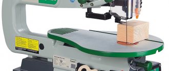
Types of planing machines
Wood planing machine
The design of the clamping mechanism directly depends on the equipment model. Therefore, it is first necessary to carefully study the technical documentation, the features of the machine elements, and their characteristics.
The most common option is a power unit (electric motor) that drives a cylindrical cutter head. Its upper part is located above the level of the support table. The latter can move relative to the cutting part in the vertical direction. In this way, the depth of processing of the wooden workpiece is adjusted. You can make a similar model with your own hands.
In addition to the woodworking machine described above, the following types of equipment are used for mass production:
- thicknesser with one cutting head;
- cycle. Installed on lines for assembling furniture, door and window structures;
- two, three and tetrahedral. Processing occurs in several planes at once, which increases productivity;
- models with several knives.
Almost all modern equipment has clamps. The exceptions are machines made by yourself or old models.
When choosing a retainer design, you should pay attention to the equipment configuration. After its installation, the operational and technical qualities should not deteriorate.
Homemade clamp: option No. 1
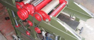
Most often, for the manufacture of the above-described design, a part from an old washing machine is taken as a basis, and in particular, rollers for squeezing out moisture. In some cases, after minor modifications, the add-on can be installed on the equipment.
The frame consists of four support legs, which are connected to each other by a U-shaped profile. Locking shafts are installed on it. The profiles are not fixed to the base, but move freely along them. At the top of the structure there is a locking bar connected to the adjustment handle by a worm gear. For shock absorption, you can install springs that will partially compensate for the strong pressure when processing uneven surfaces.
The structure consists of the following components.
Using the top handle, you can adjust the degree of pressure. The disadvantage of this model is its large massiveness. It may not be suitable for all types of machines.
To reduce the labor intensity of manufacturing a mechanism for a planer, you can use the rollers of a washing machine. They need to be trimmed first.
Setting up the spring block
The package of flexible clamping elements is rotated around the main axis by the second rod—the clamping axis. It is parallel to the axis of rotation, fixed at its ends in supports, but the height of its position can be changed (along an arc).
The clamping axis is moved by the master, manually, before planing. Thus, it regulates the force of pressing the material by the spring block (depending on the thickness of the workpiece). The specified position of the movable rod is fixed with a handle (thumbscrew).
Important! The cutting edge of the blades in the upper position should be flush with the working surface of the receiving table. The gap between the edge of the receiving part of the table and the circle that the knife blades describe is permissible no wider than 3 mm.
Homemade clamp: option No. 2
An alternative option for making a machine clamp with your own hands is a slight modification of the equipment. It consists of installing two slats on the sides of the frame. Two bearings are installed in the main working shaft, through which a fixing axis passes.
The difficulty may lie in the configuration of the bed. All models have smooth edges to allow mounting of eyelets. The degree of clamping is adjusted using a spring. It moves along the slats, thereby changing the pressure on the workpiece.
Review and comparison of factory models
| Model | UP-2000 | UP-05 | UP-2200 | UP-2500 |
| Processing width, mm | 230 | 200 | 250 | 270 |
| Workpiece thickness, mm | 8-63 | 8-63 | 8-63 | 8-63 |
| Weight, kg | 3 | 2,5 | 3,2 | 5,6 |
| Dimensions, mm | 293*304*113 | 255x270x105 | 293*324*113 | 293*344*113 |
| Price, rub | 2871 | 2871 | 3133 | 3393 |
UP-2000
UP-05
UP-2200
UP-2500
Homemade jointing machine: sketch, main manufacturing stages
For any work to be successful, you must have good equipment and tools. The same statement applies to amateurs (or professionals) “tinkering” with wood. Craftsmen who make furniture or other wooden products always try to acquire various tools and devices that can help them in their work.
For example, a jointer. This device significantly increases the productivity and quality of woodworking. But not all fans can purchase it, because its price is quite high. How to get out of such a difficult situation? There is a solution, and it’s quite simple - it’s to make a tabletop jointer with your own hands. And the manufacturing process itself will be discussed in the article.
Safety when working with homemade equipment
When working with any tool, you must follow safety precautions, as ignoring them can cause various injuries. We will briefly list the recommended measures to ensure the safety of the master’s work on this machine.
- It is recommended to remove sharp chamfers and sand all manufactured parts to eliminate the possibility of hand injury (splinters, etc.)
- When working, it is necessary to use a chip extractor or a special vacuum cleaner, for example, a cyclone type, to remove sawdust and dust from the sawing area, which can cause the following harm:
| To the Master | Respiratory and eye contact |
| Tool | Getting inside the instrument and: |
- deterioration of lubricant properties, resulting in overheating
- difficulty in moving parts of the tool, resulting in overheating
- clogged air passages for cooling the instrument, resulting in overheating
- When working, it is necessary to use pushers, since when working with small parts, it is possible that the master’s hands will get into the cutting zone, which will lead to injury.
Why do you need a jointer?
A woodworking shop can have a variety of machines, but the most commonly used (besides the circular saw, of course) are jointers and planers. These two types of units are slightly similar in their function, but differ in the method of use.
Thicknessing machines are available in both single-sided and double-sided types. In the first case, only one side of the workpiece is processed in one pass. A double-sided thickness planer is more productive. Here the output is an almost finished part.
Thicknessing machines have a shaft located above the tabletop. Moreover, the latter is made massive in order to smooth out large vibrations. In addition, the mechanism is equipped with a special casing, which is designed to dampen noise.
A jointer has a slightly different task. This device is used to create a smooth surface without significant roughness on the workpiece. This machine, like the previous version, is equipped with a shaft with knives, only in the jointer it is located under the table top.
The workpiece is fed onto the work surface from one side, and the output from the opposite side is already partially processed. This way, layer by layer, the desired evenness is achieved. After processing on a jointer, the part can be fed to a surface planer.
Clamps for circular saws
In terms of handicrafts, the year has gotten off to a great start! Unfortunately, as has become customary lately, according to the principle “I take one berry, look at another, notice the third, and crush the fourth...”.
In the sense that work is going on simultaneously on several projects, none of which have yet been brought to a demonstrable state. But - give it time! In the meantime, here I have something from the instrumental series.
I had to build myself some accessories that were vital in the current work.
- * * *
- Some time ago, one of my current projects required me to create a feeder for a circular saw. This is a tray with sides rolling on the table:
- Needed for neat and precise sawing of small pieces of material or for all sorts of tricks with plywood, such as bending it (for which, in fact, the feeder was made):
The idea, I think, is clear: many non-through cuts are made in a strip of plywood, which makes it quite easy to bend. When the shape is simple, this method is much faster and simpler than gluing veneer onto a blank, steaming, etc.
But it is obvious that without the feeder mentioned above, making such cutting is very difficult. It is also obvious that the scope of application of the feeder is not limited to this. I've wanted to build it for a long time, but there was no reason. The reason appeared - I did it.
The design is simple as hell. A sheet of plywood with two sides set exactly at 90 degrees:
- Rolls on the table due to the guides fixed on the bottom side:
I simply milled two T-shaped profiles from oak, which fit exactly into the grooves of the circular table.
All this is too simple and does not carry any special adventures. All woodwalkers sooner or later build themselves a similar feeder for a circular saw. This is inevitable.
This was all, like, an introduction. Now, to the point of the post...
* * *
The feeder, made when it was necessary to cut plywood, suddenly became needed almost constantly. It's amazing how quickly these types of accessories are integrated into the workshop.
As a result, problems arose that you didn’t initially think about when making adjustments for a specific task. In particular, it turned out that beyond this specific task, the feeder ceases to be convenient without the ability to reliably fix the material in it.
Basic Concepts
Such equipment will have numerous rotating parts. From this we can conclude that making such a machine with your own hands will not be so easy. Therefore, when starting to manufacture it, you need to calculate your strength. If you already have some similar experience, then you will cope with the task. It is worth noting right away that you will not be able to make a jointing machine entirely from parts of your own making. Of course, it’s possible that you have a large assortment of different devices in your “bins,” but this rarely happens. First of all, this concerns the shaft with knives and bearings. They will most likely have to be purchased or even ordered. But if everything you need is available, then you can safely start designing.
Advantages and disadvantages of using a clamping device
Advantages of planing with a clamping device:
- there is no need to bring your hands closer to the cutting device of the machine;
- processing of thin lumber is possible;
- the workpiece is adjacent to the blade along the entire width with the same pressure, planing occurs to the same depth;
- devices of sufficient width cover the entire blade shaft;
- adjustment of the pressing force allows you to set the optimal angle formed by the front edge of the cutter and the cutting plane;
- the workpiece does not come off the feeding and receiving surfaces of the table, no chips or scuffs are formed.
On a note. The smaller the cutting angle during planing, the more likely the appearance of flakes and chips. Too large an angle can cause chips to break.
The use of a clamping device can lead to time expenditure: for setting up the clamps, as well as for dismantling before processing a part of large thickness.
Electric drive of the jointer
And of course, don’t forget about the drive. All mechanisms must rotate. This means that the drive will be the “heart” of the machine. Here are some recommendations for this design element: - first of all, prepare the electric motor.
Electric motor for jointer
It is best to use a three-phase unit for these purposes. Of course, in this case you may have to redo the electrical network in your workshop, but it will be worth it. Three-phase electric motors operating at a voltage of 380 V are capable of developing greater power. In addition, the torque of such devices is suitable for our purposes. The minimum power value should be 3 kW, but the maximum is at your discretion;
Be very careful about providing power to the machine. Three-phase current is supplied through a four-core cable. In this case, reliable grounding must be organized. These requirements will help avoid accidents when working on the machine.
Making a thicknesser with your own hands - drawings of a homemade planing machine
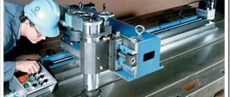
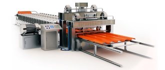
In the woodworking industry, it is difficult to do without modern carpentry equipment, which is used to process timber and boards, giving their sides a perfectly flat surface. For these purposes, a planing machine is designed that can cope with large-area products.
A home-made surface planer is lightweight, so it can be easily installed or removed as unnecessary and transported to another place. It has simple adjustments, is easy to operate and provides high quality surface finishing.
At the design stage of a thickness planer, the configuration of the future equipment is determined. In factory models, feeding is carried out by the upper rollers, which require correct adjustment of the rotation speed, which is difficult to do at home . Homemade designs, on the contrary, should be extremely simple. To facilitate the process of their manufacture, they abandon the automatic feeding of the workpiece for its processing and use a jointer as a basis - another type of woodworking tool.
In addition, the following characteristics of the future planing machine should be provided:
- The ability to change the position of the support table, which is necessary to adjust its height relative to the cutting shaft.
- Selection of processing tool. The best solution is to use spare parts from an old factory model that have the required technical parameters.
- Availability of a stable frame. Vibration inevitably occurs during equipment operation, so to increase the quality of processing, it is necessary to reduce its impact on the workpieces being processed.
To implement the assigned tasks, they draw up the correct scheme, taking as a basis the drawings of factory models and ready-made technical solutions. Be sure to take into account the experience of making homemade surface planers, as well as the dimensions, thickness, and type of wood of the workpieces being processed.
If you have the necessary tools and materials, assembling thicknessing equipment for wood will not take much time. You will need:
- lathe for making rollers and pulleys;
- drilling machine or drill for making holes in fasteners;
- welding machine for assembling the feed table, frame;
- grinder for cutting and adjusting structural parts to the required size.
There are many options for how to make a thicknesser with your own hands, but the optimal dimensions for a homemade device should not exceed 1x1 meters. These parameters allow you to process workpieces of any size, while the product turns out to be mobile and will be convenient to rearrange or transport to another place. The equipment is located in such a way as to provide access from all sides.
If stationary use is planned, then in order to prevent the occurrence of excessive vibration in the future, the frame is concreted and secured with anchor bolts.
The first step is to assemble the frame according to the previously drawn up drawings. To give the structure the necessary rigidity, take an iron corner of 50x50 mm, or, in its absence, a profile square pipe of 40x40 mm.
The marked elements of the frame are cut using a grinder with an abrasive wheel. Having laid them out on level ground, they are assembled according to the diagram and the frame is welded. Mark the holes for fastening the removable parts and, using a drill, drill them.
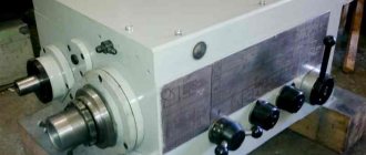
Having completed the welding work, they begin to install the shafts: knife, pressure, feed. To obtain high-quality products, it is better to purchase a complete knife shaft assembly or ready-made planer knives. If possible, pressure rollers are made from hand-held linen wringer from old washing machines, the rubberized surface of which will gently but firmly hold the workpiece on the desktop.
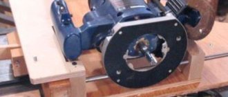
It is preferable to install gear pulleys for the motor and shafts, which will allow the use of a chain drive, which is characterized by a high degree of reliability. An asynchronous electric motor with a power of 4–5 kW is chosen as the engine. The schematic diagram of the arrangement of parts is shown in the figure:
1 – work table for feeding and dispensing workpieces; 2 – wood preparation; 3 – safety device; 4 – upper feed roller with a corrugated surface; 5 – front clamp; 6 – knife shaft; 7 – rear clamp; 8 – feed upper roller with a smooth surface; 9 – lower smooth shaft
The table base consists of rear and front parts, which are mounted on prepared adjustment devices. They are used to change the height of the table and the position of the workpiece being processed. Before starting work, be sure to check the location of the knives, the reliability of fastening and the correct sharpening.
The setup is carried out as follows. The support rollers (8) are lowered below the level of the table (10), and the tabletop itself is lowered so that a pre-treated wooden block laid on it passes freely under the blade shaft. Slowly raise the table, simultaneously turning the shaft until it touches the surface of the block. At the moment of contact with the upper edge of the knife shaft, the position of the table is fixed.
Having lowered the working surface by 0.3 mm, the block is moved under the rear clamp (3), which is adjusted with screws (2), trying to get the template to touch. Additionally, it is lowered by 0.7 mm (total 1 mm from the initial level) and the measuring stamp is placed under the front clamp (5), the height of which is set with adjusting screws (6) until it touches the bar.
Having lowered the working surface another 0.5 (1.5 mm from the initial level), adjust the rear pressure shaft (1). Continuing to lower by 0.5 mm, use the measuring template to change the height of the grooved feed roller (7). Lowering it another millimeter, the measuring template is placed under the claw protection and the height is adjusted until it touches. Finally, the support rollers are placed above the table surface.
Drawing. The main stages of creating a jointer
Tabletop jointer - drawing
Tabletop jointing machine - drawing (part 2)
A jointing machine, its simplest version without additional functions, can be made quite easily with your own hands. The general progress of work in this case will look like this:
When fastening, glue and clamp are used. The recess should ideally fit the dimensions of the bearing;
After creating the system for turning the electric motor on and off, the machine is ready for use. But in order for your new tool to bring only benefit and joy to work, it is worth using it correctly and safely.
How to make a surface planer with your own hands is simple.
One of the important tasks when preparing material in woodworking is planing blanks to size in thickness. This problem is usually solved with the help of a thicknesser or, more correctly, a thicknesser.
In this publication we will not talk about industrial machines, but about how you can solve this problem - planing workpieces to size in thickness using a conventional electric planer.
When my home workshop was just beginning to take shape, the need arose to make chairs. The material for the chairs was an unedged beech block and it first had to be planed to size before making the chair parts.
I only had an electric planer and I decided to make a small device so that I could plan with a planer like a surface planer. Moreover, the possibilities of the device turned out to be greater than those of a thickness planer, but more on that later.
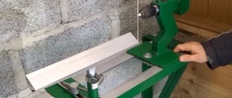
First version of the device.
The device turned out to be really simple - a base about 1.5 meters long with bars along the edge the length of the side, a frame on top and a hanger for the plane.
The board that needed to be planed was placed on the base and wedged. The frame is made along the length of the plane. The height of the plane above the workpiece was adjusted using paired slats of different thicknesses.
You need to plan with such a device as usual with a plane, going through one strip, I returned the frame with the plane to the original one, shifted the plane in the frame and went through a new strip. This was done several times until the plane reached the workpiece at a given thickness of the pads. Then other pads were placed to reduce the height of the plane above the base and the process was repeated.
That is, as in a regular thicknesser, only the workpiece is motionless and the width of the workpiece is traversed several times.
For clarity, you can watch the video
Second version of the device.
Later I modified this design to get away from adjusting with shims and increase the width of the planed board.
Adjustment of the height of the plane turned out to be more accurate. The elements of the device are easily mounted on a workbench.
The design is a little more complex than the first version. The planer binding was made for a specific plane.
In order to use this device to obtain a well-planed surface of the workpiece, you need to install the knives into the plane evenly and without distortions. For information on how I install and configure knives in a planer, see this article - How to install knives in an electric planer
The video below shows a demonstration of how this device works.