A note for the novice milling operator - dividing heads for the router
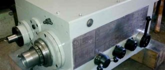
The dividing head is a device for periodically rotating the workpiece for subsequent fixation of its surface in the processing zone at the calculated angle.
The production of gears, giving parts flat, shaped and other configurations with the required accuracy, is carried out by milling blanks that are periodically shifted relative to the processing axis.
Design Features
Created for a milling machine, the mechanism can be used on other types of equipment. The device rotates and fixes the workpiece without removing it from the clamping device until the processing is completed.
It is technically not possible to divide the circumference of a part with ensuring accuracy directly in the working area of the machine without the use of a dividing mechanism. (Only clamping systems of CNC machining centers are competitive).
The device also features:
- The workpiece is rotated to any angle with the minimum permissible error.
- Metalworking capabilities increase by an order of magnitude.
- Long workpieces are fastened using a tailstock.
- The cutting tool is constantly adjusted to size.
- The workpiece is fastened with the smallest deviation error from the base parameter.
The operating functions of the devices are:
- securing the workpiece;
- its periodic rotation and fixation.
The purposes of the structural elements of different types of installations are the same and consist of:
- metal case;
- rotating part of the head;
- clamping mechanism and division fixation.
The completeness of the scope of tasks is determined by the design elements and there are three types:
- simplified (or direct division);
- universal dividing head;
- optical head.
Simplified dividing heads
Direct division. They have a design of low complexity and are used in the manufacture of standard parts in large quantities: milling slots, grooves, splines and edges of parts. No experience or skills in operation and maintenance are required.
You might also be wondering what a copy sleeve for a router is.
Universal dividing heads (UDG)
The device (UDG) is intended for the production of parts that require a larger division limit than in simplified mechanisms. Selected according to the size of the milling machine. For example: with a table width of 400 mm, UDG-D320 is used. The index (D320) means that the diameter of the part cannot exceed 320 mm.
UDG models are common in industry:
- D160 and D200 with workpiece diameters up to 160 and 200 mm, respectively.
- D250 – for processing massive parts with a diameter of up to 250 mm.
- D320 – workpiece diameter up to 320 mm. With a set of replacement gears and two guitars for them.
- D400 – Dividing disk with a number of holes from 16 to 31, on the one hand, and from 33 to 54, on the other.
Optical dividing heads
In demand when processing cutting tools with a large number of blades. A glass disc with 360° graduation is mounted on the spindle. Visually, using the eyepiece, the angle of rotation is set with the required accuracy.
By rotating the flywheel on the worm wheel shaft, the spindle is rotated. Coupled with the worm wheel, it rotates at the calculated angle and is fixed with a handle located on the housing panel.
Models equipped with a screen make it easier to apply divisions and markings to the workpiece, as well as check the correctness of previously applied hatches.
DIY making
The cost of such equipment can be quite high. This is why many people wonder how to make a dividing disk with their own hands. A drawing of the future product is created depending on the characteristics of the equipment on which the dividing head will be installed. In addition, you will need the following components.
- Lathe chuck with dial.
- Limit screw.
- A worm gearbox, which can be obtained by dismantling old machines or made with your own hands.
After manufacturing the product, the dividing part is adjusted. To do this, you can use any previously manufactured part. After obtaining certain results, a final calibration is performed, which can significantly improve the processing accuracy.
The immediate process of setting up an element can be described as follows.
- The transformation of 360 degrees of the disk is carried out by the required number of divisions, due to which sectors are allocated.
- The calculated value of the sine of the angle is displayed.
- The disk is set according to the result obtained. It is important to maintain high precision when installing the equipment in question.
- The body is fixed using a special mechanism or handle.
After this, you can install the main working part of the tool.
Industrial dividing heads can cost more than 100,000 rubles. Homemade devices cost about 40-50 thousand rubles, but have comparatively less versatility, reliability, and accuracy in use. As previously noted, it is important to consider proper installation.
Benefits of using UDG
Indispensable for the processing of massive parts by tool, repair and restoration and experimental shops in the conditions of piece production. Application in mass or serial production is costly and, often, technologically not justified.
- milling of surface grooves and edges of any complexity;
- with ensuring accuracy, create edges on workpieces, on nuts with non-standard parameters, on the shanks of cutting tools;
- cut grooves, splines and polyhedrons;
- mill sprockets, as well as hollows between wheel teeth.
Purpose of the equipment
A homemade dividing head for a lathe or milling equipment is installed to offset the part relative to the axis of the installed cutting tool with certain indicators.
In this way, it is possible to achieve precise positioning of the tool and the workpiece relative to each other in each position. The device can be used for various types of processing. In order for work to be carried out with high precision, it is also important to eliminate the possibility of vibration of the device. A variety of fastening methods are used, it all depends on the design features. The position can be adjusted during operation of the machine using a movable disk or handle.
The capabilities of the equipment in question include the following points.
- Surface milling to form splines and grooves. The complex configuration of a future part requires the use of special equipment that allows maintaining a certain distance between splines or grooves, as well as their dimensions.
- Milling the surface of an already created groove. Such work is quite difficult to perform, as it requires maximum precision when monitoring the width and depth of the formed recess.
- It is possible to partially automate the process of creating edges on parts. An example is the process of creating nuts with non-standard parameters. Such work also requires high precision.
For normal processing, such equipment is not required.
Division methods
Angular displacement of workpieces is carried out using the following methods:
- Direct division. It is carried out visually using an optical device without the use of intermediate mechanisms.
- Simple division. It is carried out by a fixed UDG disk. Characterized by a wide range of applications.
- Combined division is also carried out using a dividing head.
- The differential method is applicable to UDGs that have a set of replaceable gears.
- The continuous method is implemented by optical and universal heads that have a kinematic connection between the spindle and the longitudinal feed screw of the machine.
How to use?
With the direct division method:
- The worm pair is disengaged by the control handle.
- The dial stop lock is released.
- The spindle rotates by an angle measured by the vernier dial and is fixed.
With a simple division method:
- The dividing disk is fixed in one position.
- By installing the locking handle into the hole on the dividing disk,
- The device moves to the calculated angle.
Differential division method:
- The spindle is set to a horizontal position.
- The smooth rotation of the gears is checked.
- The disc stopper is disabled.
- Further actions are the same as in the simple division method.
Which one is better to choose?
When choosing, the conditions that dictate the selection criteria are considered:
- Parameters of the head and fastening elements on the frame.
- What kind of work do you need a head for:
- for piece repairs or restoration - you need an UDG;
- for high-precision – optical head;
- for flow operation – a head of a simplified design.
Value for money. Cost recovery. New or used. Selecting the country and brand of the manufacturer.
Dividing heads and their settings
When processing teeth, splines, grooves, cutting helical grooves and other operations on milling machines, dividing heads are often used. Dividing heads, as devices, are used on cantilever universal milling and wide-universal machines. There are simple and universal dividing heads.
Simple dividing heads are used to directly divide the circle of rotation of the workpiece. The dividing disk of such heads is fixed on the head spindle and has divisions in the form of slots or holes (in the number of 12, 24 and 30) for the latch latch. Discs with 12 holes allow you to divide one revolution of the workpiece into 2, 3, 4, 6, 12 parts, with 24 holes - into 2, 3, 4, 6, 8, 12, 24 parts, and with 30 holes - into 2 , 3, 5, 6, 15, 30 parts. Specially made dividing disks of the head can be used for other division numbers, including division into unequal parts.
Universal dividing heads are used to set the workpiece being processed at the required angle relative to the machine table, rotate it around its axis at certain angles, and impart continuous rotation to the workpiece when milling helical grooves.
In the domestic industry, universal dividing heads of the UDG type are used on cantilever universal milling machines (Fig. 1, a). Figure 1, 6 shows auxiliary accessories for dividing heads of the UDG type.
On widely-universal tool milling machines, dividing heads are used that are structurally different from dividing heads of the UDG type (they are equipped with a trunk for installing the rear center and, in addition, have some differences in the kinematic diagram). The settings for both types of heads are identical.
As an example in Fig. 1, a shows a diagram of processing a workpiece by milling using a universal dividing head. The workpiece / is installed on a reference in the centers of the spindle 6 of the head 2. and the tailstock 8. The modular disk cutter 7 from the spindle of the milling machine receives rotation, and the machine table receives a working longitudinal feed. After each periodic rotation of the gear blank, the cavity between adjacent teeth is machined. After processing the cavity, the table quickly moves to its original position.
TPK, aka LUAZ 967
October 22, 2012, 10:06 pm
The idea of equipping a lathe with means for precise positioning of the spindle is not new - many industrial machines have a spindle degree scale, and on the Internet there were designs in which a dividing disk was attached to the spindle shank, turning the spindle into a direct dividing head. But at the same time, you still need a spindle brake, so that it does not move the spindle when tightening. But isn't there a better way? For example, the spindle already has a guitar drive gear (45 teeth), and it’s metal - but couldn’t it be used as a worm wheel? Hm. why not?! And the gear teeth are straight - so you can tilt the worm axis!
We remember what a gear tooth module is and calculate the screw pitch for it - we get for module 1 step is equal to Pi, or
3.14mm. We indicate this step in the Gear Calculation Program. It turns out that with the existing set of guitar gears you can cut a pitch of 3.1429, which differs from the required one by only 0.04%, excellent!
Five minutes - and you have a ready-made worm in your hands. Let's try it on a similar gear:
Seems not bad. Now we mock up the location of the axis on the machine, measure the resulting dimensions and angles, and make a drawing of the bracket. From the drawing it turns out that for ease of manufacture it is better to make it from several parts. In the process of manufacturing the parts, we redo the drawing a couple more times, and finally it takes on its final form, and a number of simple parts based on it are already ready. One subtle point arises here - the axis must be tilted 11 degrees “towards itself” relative to the axis of the machine, and 10 degrees to the right, but how can this be done on a lathe? It turns out to be easy - just turn the small longitudinal support and the milling table to the required angles at the same time, securing the part to the latter.
Then the rest of the details are made, and everything is assembled for the first fitting.
With some excitement, the design is tried on the machine.
And finally it becomes clear - the idea is sound, the design will live!
All that remains is to drill a hole in the aluminum body of the guitar for the locking screw and make a dividing disk. A new aluminum frying pan was purchased and sacrificed for the disc. The middle part of the maximum size processed on the machine is cut out of it with a jigsaw, then it is ground.
Dividing heads for milling machines: division table, prices
The two main devices for precision metal processing - lathes and milling machines - are based on rotation and transformation. Various types of gears, racks, worm screws, clinging to each other, increase the force, change the direction and speed of movement. Milling dividing heads are used to mark and manufacture all these parts. Their capabilities are not limited to cutting teeth. These units are capable of producing multifaceted products, such as nuts, as well as a whole list of complex parts that include all these elements. This interesting device will be discussed in the article.
Equipment and functions
The dividing head is included in the package of console milling machines with manual control. The price of the machine does not include the device. The owner decides whether to buy it or not, but it is worth buying it, despite the high cost, since the capabilities of the milling machine with it are significantly expanded.
Using a dividing head:
- The part is installed at different angles relative to the longitudinal axis of the router table.
- Rotate to an exact angle after each cutter pass.
- They carry out continuous rotation of the part in the process of cutting spiral grooves or teeth, for example, in the manufacture of taps, mandrels, products in the form of an Archimedean spiral and others.
The device body is placed on a massive frame. In universal models, it is capable of rotating relative to it in a vertical plane. The support part is equipped with two T-shaped protrusions that serve for installing and fixing the device on the work table of the milling machine.
In addition to the main dividing part, the mechanism is equipped with additional devices:
- The tailstock serves for additional fixation of the opposite end of the workpiece.
- Steady rests are supports for long, thin parts such as shafts, axles, and racks. There is no equipment included in the basic configuration, but buying it separately will not be a problem.
- Three-jaw self-centering chuck where the workpiece is clamped.
- Mandrel. Used in the differential marking method to install additional gears of the so-called “guitar”.
Universal key made of bolt and chain
Sometimes there is a need to make a wrench for a nut of a non-standard shape. The nut may be round and have no edges that can be grasped with an open-end wrench. Or, on the contrary, the nut may not have parallel edges - the nut is in the form of a triangle, and accordingly, such a nut also cannot be taken with a regular wrench, the main condition for working with which is that the nut or bolt has at least two parallel edges.
For such or similar cases, you need to make a universal key
Let's not go into the wilds and make a key from scrap materials, without involving welding and cutting work. True, you will still have to drill.
We buy an M10 bolt 150 - 200 mm long from the store. A sufficiently long bolt is needed so that the leverage on the nut is large, this will make the work easier. The bolt will serve as the handle of the key.
Using a drill with a diameter of 3 mm, we drill a through hole at the end of the bolt (5 mm away from the edge). We will insert an M3 Bolt into this hole; it should pass through the entire hole of the bolt and protrude from the opposite side by 20 - 30 mm.
But we don’t just insert a thin bolt into the hole of a thick bolt, but first we string a chain link onto it, which is the outermost link of a long chain. Then we insert the bolt into the hole and screw the nut onto it. This way we tighten the chain to the bolt.
Actually, with this the universal key can be considered done
You need to operate the wrench as follows: place a chain loop over the nut or bolt head, hook the free chain link (the one closest to the nut) onto the protruding short bolt. Straighten the remaining chain along the bolt - the handle.
You start to rotate the key, the chain tightens, compresses the nut, and the nut unscrews.
Types of heads
The classification of heads is based on the methods of their use and the features of the device.
Based on these characteristics, mechanisms are divided into:
- With dial scale.
- Limbless.
- Optical heads (ODG), allowing division to be carried out with an accuracy of fractions of seconds.
The vast majority of milling machines use the first type, which in turn are divided by type into heads:
- direct and direct division;
- simple and differential division.
Table of contents
- Methods of performing work
- Design and principle of operation of the dividing head
- Work order
- Division table for dividing head
- Calculation of the dividing head
- Video
It’s no secret to milling specialists how to use a dividing head, but many people don’t even know what it is. It is a horizontal machine tool that is used on jig boring and milling machines. Its main purpose is to periodically rotate the workpiece, during which division into equal parts occurs. This operation is relevant when cutting teeth, milling, cutting grooves, and so on. With its help you can make gear teeth. This product is often used in tool and machine shops, where it helps to significantly expand the operating range of the machine. The workpiece is secured directly in the chuck, and if it turns out to be too long, then in a steady rest with emphasis on the tailstock.
Types of work performed
The UDG device allows you to provide:
- Precise milling of sprockets, even if the number of teeth and individual sections is several dozen;
- It is also used to produce bolts, nuts and other parts with edges;
- Milling of polyhedra;
- Grooving the depressions located between the teeth of the wheels;
- Grooving of cutting and drilling tools (for which continuous rotation is used to obtain a spiral groove);
- Processing the ends of multifaceted products.
Methods of performing work
The operation of the dividing head can be done in several ways, depending on the specific situation and what operation is being performed on what specific workpiece. Here it is worth highlighting the main ones that are most often used:
- Direct. This method is carried out by rotating the dividing disk, which controls the movement of the workpiece. The intermediate mechanism is not involved. This method is relevant when using such types of dividing tools as optical and simplified. Universal dividing heads are used only with a frontal disc.
- Simple. With this method, counting is carried out from a stationary dividing disk. The division is created using a control handle, which is connected through a worm gear to the spindle on the device. With this method, those universal heads are used on which a dividing side disk is installed.
- Combined. The essence of this method is manifested in the fact that the rotation of the head itself is a kind of sum of the rotation of its handle, which rotates relative to the dividing disk, located motionless, and the disk, which rotates with the handle. This disk moves relative to the pin, which is located on the rear clamp of the dividing head.
- Differential. With this method, the spindle rotation appears as the sum of two rotations. The first refers to the handle rotating relative to the index disk. The second is the rotation of the disk itself, which is carried out forcibly from the spindle through the entire system of gear wheels. For this method, universal dividing heads are used, which have a set of replaceable gears.
- Continuous. This method is relevant when milling spiral and helical grooves. It is produced on optical heads, which have a kinematic connection between the spindle and the feed screw to the milling machine, and universal ones.
Device classification
The dividing head for a milling machine, the table of technical parameters determines what kind of work can be carried out on this or that equipment. Considering the classification of the dividing head, we note the following types of device.
- Simple model. Its distinctive features include light weight and ease of control. The main part of the structure is represented by a spindle, which is connected to a disk limb.
- Combined model. This version can be adjusted with a special handle. By increasing the number of clicks, you can increase the distance between the center axis of the workpiece being processed and the installed cutting tool.
- Universal samples represented by complex models. In this case, adjustment is carried out using a disk element and a handle. The complexity of the design is determined by the presence of differential gears.
Repairing almost every design option is complicated, since you need to know the principle of operation and carry out the manufacture of all parts.
Adjusting the universal head for simple division.
Simple division
It is used when it is possible to select a concentric circle for reference on the dividing disk (limbe). A single-thread worm is engaged with a worm wheel. The dividing disk is fixed motionless using a latch. Rotate the spindle with the workpiece
part (z—the number of parts by which division is required) must be made in
n
turns of handle 2.
The final links of this kinematic chain are: the handle of the universal dividing head—the spindle with the workpiece.
Calculated movements of the end links:
n
hands→
workpiece revolutions.
The equation for the kinematic balance of the chain during dividing rotation of the workpiece will be written as follows:
,
where i tooth
=1;
i hearts
=
.
The formula for setting up a universal dividing head is as follows:
The reciprocal of the gear ratio of the worm pair is called the characteristic of the dividing head (N=40).
The number of teeth of the worm wheel is 40, but there are 60, 80, 120.
Transforming the previous formula, we get
=
where a
—integer number of handle revolutions;
c
is the number of holes in one of the rows of the dividing disk;
b
is the number of holes (steps) by which the handle must be additionally turned.
Dividing disks of universal dividing heads have a series of concentric circles with the following number of holes:
on one side -16, 17, 19, 21, 23, 29, 30, 31;
on the other hand -33, 37, 39, 41, 43, 47, 49, 54.
The dividing disk is attached to the head with four screws and can be rotated if necessary. To rotate the handle of the dividing head by part of a revolution, a sliding sector with two rulers is used, spring-loaded against each other to prevent spontaneous rotation.
Example 1.
Set up a universal dividing head for milling a gear coupling with the number of teeth z=36.
=
.
Therefore, to rotate the spindle with the workpiece by 1/9 of a turn, for the denominator of the fraction we select a number that is a multiple of 9 from a series of numbers, and in order for the fraction not to change, we multiply the numerator by the same number. In our example, we multiply both the numerator and denominator by 6. The handle of the dividing head should be turned one full turn and six steps each time. The sliding sector rulers are installed (extended) into six holes, not counting the seventh, into which the index head handle clamp is inserted.
Giving a hexagonal shape
At this stage, it will be more convenient to work if the metal is heated. (I did not maintain a constant temperature and was unable to bend the entire piece in one piece).
Clamp the strip in a vice at the level of the previously made recess.
Use a hammer to bend the section protruding from the top of the vice.
Check if the angle fits by trying it on the corresponding nut.
Repeat for each segment.
As my strip cooled, the metal became more difficult to work with. This led to a breakdown over the third segment. In my case, this worked to my advantage, because when I started bending the fourth section, it turned out that its length was not enough and I needed to grind off a little metal so that the nut would fit properly. (I think adding a millimeter to each cut will help avoid running out of length on the inside edge of the key).
So I got a part consisting of two parts, each with three sides. (It may be easier to work with this than with a solid piece curved into a ring, as I originally planned to do).
Check that the workpiece fits properly onto the nut. But not too tight. (If necessary, you can grind off part of the inner surface of the edges)
