Jig boring units have a special place in the world of machine tools, because they perform one of the most difficult tasks - creating high-precision holes with minor deviations in placement relative to each other. Such equipment has a special reading device, which makes it possible to perform high-precision processing of workpieces. The error when drilling holes is up to 1 micrometer. Additionally, coordinate machines are equipped with a device that controls possible deviations, which makes the work process almost like jewelry.
This type of technique is used in the processing of center-to-center holes if it is necessary to achieve the most accurate distances in accordance with the coordinates . During the processing of workpieces, no additional structures are needed to guide the tool.
Information about the manufacturer of the jig boring machine 2450
Manufacturer of jig boring machine 2450 Moscow Jig Boring Machine Plant MZKRS , founded in 1942 and Kuibyshev Jig Boring Machine Plant (Kuibyshev Machine Tool Association).
The Kuibyshev Jig Boring Machines Plant traces its history back to 1963, when the first stage of this enterprise was put into operation. The young team of the plant quickly mastered the production of high-precision machine tools and already produced several hundred of them in 1966.
The plant ceased to exist in 1991, and several machine-tool manufacturing enterprises opened on its production sites, which continue to produce jig boring machines, are engaged in their repair and modernization: Plant of jig boring machines "Stan-Samara" CJSC ; Samara NPP of coordinate boring machines, LLC NPP KRS; "Stankoservis" LLC, etc.
Machines produced by the Moscow plant of jig boring machines MZKRS
- 2A450
- jig boring machine, 630 x 1100 - 2D450
- jig boring machine, 630 x 1120 - 2E450
jig boring machine, 630 x 1120 - 2E450AF1
jig boring machine, 630 x 1120 - 2E450AF30
jig boring machine with CNC, 630 x 1120 - 5K822V
– universal high-precision thread grinding machine, Ø 150 - 525
— semi-automatic gear cutting machine for cutting spiral bevel wheels, Ø 500 - 2450
— jig boring machine, 630 x 1100 - 5822
universal thread grinding machine, Ø 150 - 5822m
universal thread grinding machine, Ø 150
Multifunctional CNC machining centers with 5-axis machining capability HWACHEON
Five-axis (5-axis) high-precision machining centers are required during high-speed machining and 5-axis milling of complex shaped parts. Possessing high rigidity, the design allows the use of a wide range of materials during processing, including aluminum alloys, alloy and stainless steels.
The 5-axis machining center is equipped with a tilt-rotary table, providing full-fledged five-axis processing.
The most modern CNC systems make it possible to use machining centers for milling, boring, drilling and threading.
The universal five-axis machining center is capable of performing full five-axis machining in one setup. The HWACHEON machine model M2-5AX is capable of processing large, complex workpieces that require multiple transitions in one setup. It was developed taking into account the latest HWACHEON technologies, is a leader in its class of multifunctional CNC machining centers with 5-axis processing capabilities, and guarantees high quality in the manufacture of products of any complexity.
The HWACHEON multifunctional 5-axis CNC machining center provides a complete solution to produce a finished product. The cutting mode optimization system allows you to choose a processing strategy and achieve a reduction in the work cycle time for a part and, in some cases, reduce costs in terms of the number of purchased tools. A two-axis rotary table with a diameter of 500 mm will allow processing with any combination of coordinates. The M2-5AX is designed through 3D modeling and finite element analysis. The reliability and rigidity of the structure is also confirmed by design using computer modeling and structural analysis using the finite element method. Among the wide list of additional options are proprietary software technologies for processing and monitoring of the machine, increasing productivity, accuracy and service life of the equipment.
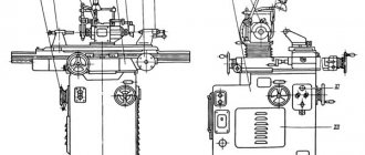
General structure and composition of the jig boring machine 2450
Arrangement of components of jig boring machine 2450
Main components of the machine:
- A - spindle head;
- B - rack with gearbox and feed variator;
- B - table;
- G - transverse slide;
- D - bed;
- E - table movement drive.
Controls for jig boring machine 2450
- handwheel for precise manual movements of the table;
- handle for turning on fast and slow table movements;
- handle for turning on the transverse mechanical feed of the table;
- handle for turning on the longitudinal mechanical feed of the table;
- handwheel for setting the table in the longitudinal direction;
- handwheel for setting the table in the transverse direction;
- handle for quick manual movement and inclusion of mechanical spindle feed;
- handwheel for manual vertical movement of the spindle;
- gearbox shift handwheel;
- spindle head movement handwheel;
- handle for securing the spindle head.
Modern MBS for hole machining
The development of innovation and technology opens up new conditions for manufacturers. The introduction of program control systems completely eliminates human participation in the operation of the machine. New generation boring machines are equipped with the latest control systems and the specialist only needs to install the machine in the required position or fix the part that needs to be processed.
Experts who use the presented systems note the ease of use and the presence of a large number of auxiliary devices. Therefore, it is quite easy to carry out work using machines of this type.
- 5
- 4
- 3
- 2
- 1
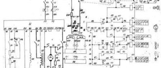
Kinematic diagram of jig boring machine 2450
Kinematic diagram of jig boring machine 2450
Movements in the machine.
- Cutting movement - rotation of the spindle with the tool
- Feed movements - axial movement of the spindle, longitudinal and transverse movement of the table
- Auxiliary movements:
- manual vertical adjustment movement of the spindle head;
- installation movement of the table in the longitudinal and transverse directions;
- manual vertical movement of the sleeve with the spindle.
Cutting movement
The cutting movement drive consists of an electric motor, a flat belt drive and a double drive (Fig. 74).
From a 2 kW DC electric motor with a stepless speed change in the range 1:4, through an angular belt drive of 150-220, rotation is transmitted to the hollow shaft located on spindle III and carrying gear 26.
The upper speeds are transmitted to spindle III when clutch M1 is engaged. The other two speed stages are carried out with the M1 clutch turned off through a bust having a double movable gear block B1.
To turn on the first stage of the search, block B1 is shifted upward so that its crown 17 engages with the wheel 69 mounted on the hollow shaft II. and clutch M1 is turned off. Rotation from the drive pulley 220 is transmitted to gears 26-60, shaft I, and then gears 17-69 to hollow shaft II, connected to the spindle by a splined connection.
The second stage of the search is activated when block B1 is shifted down, when its crown 44 engages with gear 42. Rotation from the drive pulley 220 is transmitted to the spindle by gears 26-60, shaft I and gears 44-42. In this case, clutch M1 must also be turned off.
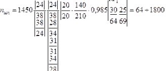
Within each stage, the spindle speed III is smoothly changed by the electric motor. The minimum spindle speed nmin can be determined from the expression:
nmin = 700·(150/220)·0.985·((26·17) / (60·69)) = 50 rpm
Serving movements
The spindle feed is borrowed from hollow shaft II, from which the movement is transmitted through gears 43-86, shaft IV, variator with sliding cones and a steel ring, shaft V, worm gear 2-32, shaft VI, bevel reverse 28-28-28, controlled clutch M2, shaft VII, worm gear 1-56, friction clutch M3, shaft VIII and rack and pinion gear 15, meshed with a rack t=3 mm, mounted on the spindle sleeve.
A mechanical variator with sliding cones and a steel ring provides a stepless change in spindle feed speeds in the range of 1: 4. The minimum gear ratio of the variator is 1/2, and the maximum is 2. The smallest spindle feed smin is determined from the expression:
smin = 1·((43·1·2·28·4) / (86·2·32·28·56))·3.14·3·15 = 0.04 mm/rev
Mechanical feed of the table in the longitudinal and transverse directions, used for fine milling, is carried out by a reversible electric motor with a power of 0.4 kW. The movement is transmitted through a chain drive 16-50, overdrive 20-84 and 14-90 (with the M4 coupling in the right position, shaft X, gears 28-50-50, worm and rack and pinion gears.
To carry out longitudinal feed, the M5 clutch is engaged. in this case, rotation is transmitted to shaft XI, worm gear 1-55, shaft XII and rack and pinion gear 14, which is in mesh with a rack m = 2.5 mm, attached to the longitudinal slide of the table. The transverse feed of the table is activated by the M6 coupling, and the movement chain is similar to the previous one: shaft XIII, worm gear 1-55, shaft XIV and rack gear 14 are driven, meshing with a rack m = 2.5 mm, attached to the transverse slide of the table.
The value s of the longitudinal and transverse feeds of the table is determined from the dependence:
s = 2800·((16·20·14·28·1) / (50·84·90·50·55)) ·3.14·2.5·14 = 37 mm/min
Auxiliary movements
To communicate rapid movements to the table, the M4 clutch is turned on to the left, and movements are transmitted to the table directly from shaft X, bypassing the overdrive. The speed of rapid movements of the s6 table in the longitudinal and transverse directions is 1000 mm/min.
For manual installation movement of the table in the transverse direction, use the Mx5 handwheel, rotation from which is transmitted through gears 24-58, shaft XV, screw wheels 15-21, shaft XIII and worm gear 1-55 to rack gear 14. By turning the flywheel Mxz along a similar kinematic chain, the table moves in the longitudinal direction.
Manual adjustment movement of the spindle head is achieved by turning the Mx4 handwheel through a worm gear 1-18. conical wheels 17-17 and rack wheel 36, which is in engagement with a rack m = 3 mm attached to the headstock body.
Fast manual movement of the spindle is achieved by rotating the handles P with the M3 clutch engaged.
Manual precise movement of the spindle is carried out by the Mx1 handwheel with the M2 clutch in the neutral position through bevel wheels 17-34, shaft VII, worm gear 1-56, M3 clutch and rack and pinion gear.
Units of jig boring machine 2450
Units of jig boring machine 2450
Switching mechanism
In Fig. 75, a shows the spindle speed switching mechanism, which consists of a flywheel 11, a bevel gear 9-10, gears 1-2, a drum 4 with two curved grooves a and b and levers 5 and 8 that switch the gear block B1 and the coupling M1 ( Fig. 74).
At the left ends of each of the levers 5 and 8 (Fig. 75, a) there are fingers with rollers 3 included in the corresponding curved groove a or b of the drum 4: at the right ends of the levers, on the eccentric fingers 7, switching crackers 6 are mounted, respectively included in ring grooves of block B| and couplings M1 (Fig. 74). The presence of eccentric pins makes it possible to adjust the position of the gear block B\ so that when it moves, the engagement of the ring gears with the gear teeth occurs along the entire length, and the stroke of the M1 coupling occurs until complete engagement.
The shape of grooves a and b on drum 4 (Fig. 75, a) and their relative position ensure a precisely defined position of block 4. The rotation of the drum is carried out by handwheel 11, located on the left wall of the gearbox housing, through a bevel gear 10-9 and gears 1 -2.
Handwheel 11 has three fixed positions: one of them corresponds to the setting for the highest range of spindle speeds, the second for the middle and the third for the lowest range.
At the first position of handwheel 11, clutch M1 (Fig. 74) is engaged, and block B1 is in the neutral position; in the second and third positions of handwheel 11 (Fig. 75, a), clutch M1 (Fig. 74) is disengaged, and block B1 is engaged with its upper or lower rim, respectively, with gear 69 or gear 42.
Variable speed drive
In Fig. 75, b shows a mechanism for steplessly changing the amount of vertical feed of the spindle. The mechanism consists of a friction variator with sliding cones and a steel ring and a control device. The variator borrows movement from the machine spindle through spur gears 8-9. Gear 9 is fixed to the drive roller 10 of the feed drive. The friction variator is made in the form of four cones 2, 3, 11 and 12 and a steel ring 4. Cones 2 and 11, located diagonally, are rigidly mounted on shafts 6 and 10 and are not able to move in the axial direction. Cones 3 and 12 are mounted on ball bearings pressed into movable cups 5 and 13. Both cups have grooves; the groove of the glass 5 includes the protrusion a of the driver 7, and the protrusion b of the driver 14 fits into the groove of the glass 12. When the drivers 7 and 14 move along the axis, the cones 3 and 12 will also move in the axial direction, and when the drivers move downwards, the cones 3 and 2 come closer , and cones 11 and 12 diverge. When the leads move upward, cones 3 and 2 diverge, and cones 11 and 12 come closer.
In any position of the cones, the steel ring 4 is always in contact with them, however, when they move, the place of contact on the generatrices of the cones changes, changing the gear ratio of the drive in the range from 1/2 to 2.
The variator gear ratio is changed by turning the handwheel 19, and the required feed rate is set using a graduated dial 20, kinematically connected to the handwheel shaft 19 by a pair of gears 18-1. When turning the handwheel 19 through the bevel gears 17 and the gear 16, the gear-nut 15 is rotated, which is connected to the threaded shank of the driver 14; the latter, when the gear-nut rotates, moves together with the drivers 7 and 14 along its axis up or down, and the protrusions a and b respectively move the movable cones 3 and 12 up or down, changing the gear ratio of the variator.
The number of revolutions of the machine spindle is adjusted by handwheel 9 (Fig. 73) on the tachometer scale 22 (Fig. 75, b), kinematically connected to shaft 10 by screw gear 21. Shaft 10 is driven by the machine spindle.
Control mechanism
In Fig. 75, c shows the mechanism for turning on and off the mechanical feed of the spindle. The mechanism consists of operating handles 1, a rack rod 2, a coupling with a split ring 3 and a block 4. Each of the handles 1 on the thickened part is equipped with a toothed sector b, which is in constant engagement with the round rack of the rack rod 2.
When the mechanism is in the off position, when the handles 1 are retracted, the worm wheel 12, driven by the worm 8, rotates idle, without imparting movement to the roller 5 and rack and pinion gear 6.
To turn on the mechanical feed of the spindle, the handles / are turned towards themselves, while the rod 2 moves to the right and with its cutout a inserts the cracker 4 into the cut of the ring 3, thereby wedging the worm wheel 12 on the shaft 5. In this case, the worm 8, rotating the worm wheel 12, the shaft 5 and the rack and pinion gear 6, which is in mesh with the rack attached to the sleeve 7, imparts vertical mechanical feed to the spindle.
Manual precise vertical movement of the spindle is carried out by turning the handwheel 11 through the bevel gears 10-9, the worm gear 8-12 and the rack and pinion mechanism with the handles 1 in the on position.
Due to the fact that the handles 1 are directly connected to the shaft 5 when the mechanical feed is turned off, you can quickly manually move the sleeve 7 by turning the handles 1, the shaft 5 and the rack and pinion gear 6 connected to the rack.
Design and operating characteristics of the main components of the jig boring machine 2450
Operation diagram of the main jig boring machine 2450
In tool production, all three machine designs find equal application. Let's consider the most advanced one - a machine of the third design. This is a coordinate marking, drilling and boring machine model 2450 with optical displacement counting.
By the nature of the movements of the main parts, such a machine (Fig. 93) is similar to a vertical milling machine, but it has one more additional movement - the vertical feed of the spindle. It consists of a frame 1 with an electric motor installed on it, a spindle box 2, a spindle 3, a work table 4, its 6T slide mechanism for longitudinal and transverse movements of the work table and devices for counting these movements. The machine spindle speed can vary from 50 to 1900 rpm, and its automatic vertical feed is from 03 to 0.18 mm per revolution. Both the speed and spindle feed are steplessly adjustable.
Counting table movements
In this design, the greatest complexity and interest are the devices for moving the desktop and measuring their magnitude. The transverse movement of the worktable is carried out by a special electric motor or handwheels 11 and 12. From them, the movement is transmitted to a worm pair 14 and a gear 15 located on the frame. The worm gear and gear move the slide with the help of a gear rack 16 installed on them. A similar device is also used for longitudinal movements. Oho also consists of a worm gear 17, a gear 18 and a rack 19 connected to the work table. This mechanism is driven by an electric motor or by the above-mentioned handwheels 11 to 12.
However, the task is not only to move the table to some strictly defined distance. It is necessary to be able to accurately measure the magnitude of this movement. Such readings are made using a transverse movement counter 10 and a longitudinal movement counter 13. The counters indicate whole millimeters and their halves using a cylindrical measuring ruler 21 for transverse movement and a ruler 22 for longitudinal movement, lighting devices 20 and 7 and optical systems with eyepieces 9 and 8 , bringing the reading accuracy to thousandths of a millimeter. The measuring rulers are long polished stainless steel rollers, on the surface of which a precise and thin helical line is applied in increments of 2 mm. Parallel beams of light emerging from the lighting devices 7 and 20 fall on the mirrors 8 and 9, illuminate the helical line of the rulers and carry its image through prisms and lenses to the eyepieces of the optical systems. Two parallel lines are visible in the eyepieces and the image of a small section of the helical line of the measuring ruler is magnified 60 times.
Moving the table
Let's see how to move the table by a given amount.
Let's assume that it is necessary to move it by 241.125 mm. First of all, you need to establish the actual position of the table. For this purpose, the risks of the optical device are set so that the helix visible through the eyepiece is in the middle between these risks. Then the table is moved until the counter shows a difference of 241 mm. After this, using the dividing drum 5 and its vernier, rotate the cylindrical measuring ruler by 0.125 mm and, looking into the eyepiece, move the table again with the handwheel 11 until the image of the helix is between the eyepiece marks. As a result, the table will be moved by a specified amount.
Errors in the distance between the axes of holes bored on the described machine do not exceed ± 0.01 mm.
Adaptations
Coordinate machines are equipped with various accessories that give them wide versatility. The main devices that are available on coordinate marking and drilling machines are:
- a. round indexing table for machining circular holes
- b. a round universal table for processing holes located obliquely to the supporting surface of the part.
All coordinate marking, drilling and boring machines require especially careful handling and are carefully protected from damage, sudden temperature fluctuations and dust. For this purpose, they are installed in special closed and warm rooms.
Equipment classification
Boring units have some design features. Depending on the type of work performed, equipment can be specialized or universal.
The main feature of units of this kind is the spindle (can be located in both horizontal and vertical positions), with the help of which the axial feed is driven. Since the equipment is adapted to perform different tasks, the workpiece often goes through a full processing cycle
It is important that the product does not need to be moved between several machines
Therefore, boring machines are in particular demand in the mechanical engineering industry, where there is an urgent need for constant complex machining of parts. The main characteristic that influences the level of performance is the spindle cross-section. The working tool is fixed in it.
Technical characteristics of jig boring machine 2450
| Parameter name | 2a450 | 2450 |
| Basic machine parameters | ||
| Working surface of the table, mm | 1100 x 630 | 1100 x 630 |
| Maximum mass of the processed product, kg | 600 | |
| The largest drilling diameter in steel is 45, mm | 30 | 40 |
| The largest boring diameter in steel is 45, mm | 250 | 250 |
| The smallest and largest distance from the end of the spindle to the table, mm | 250…750 | 250…750 |
| Maximum table movement, mm | 1000 x 630 | 1000 x 630 |
| Accuracy of table installation according to coordinates, mm | ±0,01 | |
| Maximum vertical (stroke) movement of the spindle (manual, mechanical), mm | 250 | 250 |
| Maximum vertical movement of the spindle box (installation), mm | 250 | 250 |
| Distance from the spindle axis to the rack (spindle overhang), mm | 710 | 700 |
| Spindle inner taper | Special | |
| The largest cone of the clamped tool | Morse 4 | |
| Securing the spindle box to the guides | manual | |
| Feed mechanism overload protection | There is | |
| Number of T-slots on the table | 7 | |
| Amount of accelerated table movement, mm/min | 1200 | |
| Limits of working feeds when milling, mm/min | 30..200 | |
| Price for dividing the raster grid for setting coordinates, mm | 0,002 | |
| Spindle rotation speed (b/s regulation), rpm | 50..2000 | 50..1900 |
| Limits of working feeds per spindle revolution (b/s regulation), mm | 0,03..0,16 | 0,04..0,16 |
| Speed of rapid table movements in longitudinal and transverse directions, mm/min | 1000 | |
| Drive unit | ||
| Number of electric motors on the machine | 6 | |
| Main motion drive electric motor, kW | 4,5 (1800) | 2 |
| Table movement drive, kW | 0,245 (3600) | 0,4 |
| Drive for moving the slide (3600), kW | 0,245 | |
| Table spin clamp drive, kW | 0,05 (1390) | |
| Slide squeeze clamp drive, kW | 0,05 (1390) | |
| Electric coolant pump Type | PA-22 | |
| Machine dimensions | ||
| Dimensions of the machine, including travel of the table and slide, mm | 2670 x 3305 x 2660 | |
| Machine weight, kg | 7300 |
- Glukhov N.M. Working on jig boring machines, 1953
- Grigoriev S.P., Grigoriev V.S. Practice of coordinate boring and milling work, 1980
- Kashepava M.Ya. Modern jig boring machines, 1961
- Kudryashov A.A. Tool production machines, 1968
- Bernstein-Kogan V.S. Electrical equipment of jig boring and thread grinding machines, 1969
- Ipatov S.S. Jig boring machines in precision instrumentation, 1954
- Bogdanov A.V. Boring business, 1960
Bibliography:
Related Links. Additional Information
- Repair of hydraulic systems of metal-cutting machines
- Designations of hydraulic circuits of metal-cutting machines
- Repair of gear hydraulic pumps
- Adjustment of milling machines
- Milling machine repair technology
- Adjustment of screw-cutting lathe 1K62
- Designations of kinematic diagrams of metal-cutting machines
- Methodology for checking and testing screw-cutting lathes for accuracy
- Methodology for checking and testing vertical drilling machines for accuracy and rigidity
Home About the company News Articles Price list Contacts Reference information Interesting video KPO woodworking machines Manufacturers
Classification by versatility in application
Processing wood and metal involves exerting a certain force. All drilling group machines can be divided into 3 large groups:
- Universal. This type of machine is used to perform a huge number of different operations. Versatility determines that such equipment is not widely used in mass production. Miniature models are installed in home workshops for thread cutting, through and blind holes, countersinking and other operations.
- Special ones are designed to perform only a few operations. In this case, processing can be carried out in stages or simultaneously.
- Creating deep holes when creating similar products. This group has become widespread when it is necessary to establish mass production. In addition, machines specialize in performing one or more operations.