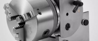
Assortment of equipment from tool
We offer a wide range of different accessories: cams, bushings, vices, collets, drill chucks and much more.
Each item is represented by several manufacturers and in the greatest possible variations. For example, there are two types of drill chuck - not only can you buy a traditional version, but also a self-locking drill chuck. In addition, it is possible to select a cartridge from various manufacturers. Vast many years of experience in the tool market allow us to best meet the needs of customers. , buy turning equipment, tme equipment.
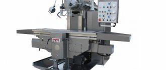
Features of turning-turret group machines
Both conventional models of turning-turret machines and devices equipped with a CNC system are distinguished by high productivity, which is achieved due to a number of factors.
- These machines are equipped with high-speed mechanisms responsible for fixing the workpiece and feeding it.
- Processing is carried out by effectively combining the work of two supports - transverse and revolving.
- All working devices of the machine are quickly replaced.
- The machines are equipped with multi-tool holders, and combined type tools are used for processing.
Of course, in order for processing on turret lathes to be highly productive, it is necessary to correctly configure all the parameters of their operation. Such parameters, in particular, include:
- a list of working tools and their installation on the equipment in the correct technological sequence;
- adjusting the position of installed tools and working devices in the radial and axial directions;
- qualified installation of stops limiting longitudinal and transverse feeds.
Most turret lathes, in particular the model 1341 and its modification 1K341, which is well known to specialists, are equipped with command devices that provide automatic switching of spindle rotation and feed modes. The use of such devices can significantly reduce the time required to perform auxiliary technological operations.
Models of machines of this group, on which a chuck is installed to fix the part, can be used for processing workpieces whose cross-section is in the range of 16–63 cm. The main characteristics of the units on which bar parts are processed are:
- maximum processing length, depending on the greatest distance that the working head can move;
- the largest section of the part that can be processed above the support or above the bed;
- the maximum distance at which the front edge of the working head can be located from the front edge of the spindle assembly.
Threading heads, threading chucks, mandrels for Optimum drilling machines
- Allows you to cut M5 - M12 threads.
- Four-speed clutch for transmitting torque.
- Built-in reverse mechanism when changing feed direction.
- Landing surface B16.
The threading head is designed for cutting threads in the range from M5 to M12 with taps. The threading head has an adjustable safety clutch, preventing breakage of the taps; upon reaching the maximum permissible forces, the head stops and it is enough to move the threading head back along the axis, and the reverse stroke is activated at double speed. Using the threading head,
spindle stroke.
you can use the machine without reversing
M7
M12
M20
And
The clamping chuck contains a device for axial thread pitch compensation. The quick-change inserts are equipped with an overload protection device (to prevent breakage of the tap). Complete set: Threading chuck KM2, d 19mm Safety heads d 19mm, for taps: M3, M4, M5, M6, M8, M10, M12. Head wrench.
| M5- | M8- | ||
| Cutting thread range | 2-7mm | ||
| Morse mandrels included | 2 and 3 | ||
| cone modification | paw | paw | paw |
| vendor code | 335 2043 | ||
| Price, rub. | 22 643 | ||
| Availability | |||
| stock | stock | stock | |
| Model | K2L-3-12 | K3L-3-12 | K3L-12-24 |
| Thread range | M3-M12 | M3-M12 | M12-M24 |
| Chuck shank | KM2 presser foot | KM3 presser foot | KM3 presser foot |
| Collets |
included
| 7pcs | 7pcs | 7pcs | |
| vendor code | P30205 | P40206 | P50207 |
| Price, rub. | 18 440 | 18 287 | 25 487 |
| Availability | in stock | in stock | in stock |
| Model | K4L-3-12 | K4L-12-24 |
| Thread range | M3-M12 | M12-M24 |
| Chuck shank | KM4 presser foot | KM4 presser foot |
| Collets |
included
TO TOP[]
THREADED CHUCK IN A SET
| 7pcs | 7pcs | |
| vendor code | P80534 | P60208 |
| Price, rub. | 18 520 | 25 487 |
| Availability | in stock | in stock |
| Model | K2-3-12 | K2-3-12 |
| Thread range | M3-M12 | M3-M12 |
| Chuck shank | KM2 | KM2 |
| Collets |
included
| 7pcs | 7pcs | |
| vendor code | P | P88150 |
| Price, rub. | 18 440 | 18 440 |
| Availability | in stock | in stock |
| Model | K3-12-24 | K4-12-24 |
| Thread range | M12-M24 | M12-M24 |
| Chuck shank | KM3 | KM4 |
| Collets |
included
TO TOP[]
THREADED CHUCK IN CNC KIT
Complete set: Threading chuck with cold-component 7:24-40BT (MAS 403), d 19mm Safety heads d 19mm, for taps: M3, M4, M5, M6, M8, M10, M12. Head wrench.
| 7pcs | 7pcs | |
| vendor code | P98159 | P09105 |
| Price, rub. | 18 642 | 25 487 |
| Availability | in stock | in stock |
| Model | BT40-3-12 | BT40-12-24 |
| Thread range | M3-M12 | M12-M24 |
| Chuck shank | 7:24-40(BT40) CNC | 7:24-40(BT40) CNC |
| Collets |
included
TO TOP[]
SAFETY THREADING HEAD
For taps
Used in conjunction with thread-cutting chucks. Designed for fastening right-hand taps in accordance with GOST 3266-81.
| 7pcs | 7pcs | ||||
| vendor code | P58105 | P68105 | |||
| price, rub. | 22 670 | 24 240 | |||
| Availability | in stock | in stock | |||
| M3 | M4 | M5 | M6 | M8 | |
| Chuck Ø mm. | 19 | 19 | 19 | 19 | 19 |
| vendor code | P 19105 | P 29105 | P 39105 | P 49105 | P 59105 |
| Price, rub. | 3 625 | 3 625 | 3 625 | 3 625 | 3 625 |
| Availability | |||||
| stock | stock | stock | stock | stock | |
| Tap | M10 | M12 | M14 | M16 | M20 |
| Chuck Ø mm. | 19 | 19 | 19 | 30 | 30 |
| vendor code | P 69105 | P 79105 | P 89105 | P 99105 | P 00205 |
| Price, rub. | 3 625 | 3 625 | 3 625 | 3 625 | 3 625 |
| Availability | stock | stock | stock | stock | stock |
УГ9321.0300.000 Six-position tool disk of a turret head
Tool disk of the turret head УГ9321
Tool disk of the turret head УГ9321
Using heads for centering work
On the heads UG9324 and UG9325, the tool for centering work is installed using auxiliary bushings in the bores of the tool disk.
Coolant supply is carried out in the working position through auxiliary bushings.
On the UG9321 heads (Fig. 5), the tool for centering work is installed in blocks (I), which are mounted on the end surface of the tool head in positions 1,3,5. When installing the block, it is necessary to unscrew plug 2 and, in the case of working with coolant, loosen screw 4, remove ball 3 and screw plug 2 into thread 5.
Eight-position tool discs are designed for installation of tool holders with a cylindrical shank GOST 24900 (DIN 69880) with a diameter of 40 mm.
Discs are made with allowances in tool holes with diameters D4.
The final processing of D4 holes into size 40H7 is carried out locally with installation on a specific dividing head.
Tool discs are manufactured at Baranovichi Machine Tool Accessory Plant OJSC, a manufacturer of universal clamping technological equipment for completing metal-cutting machines.
Design Features
Grinding heads are a special design that is used to significantly expand the capabilities of a turning group machine. This mechanism conventionally refers to equipment. Design features include:
- the presence of its own electric motor, the power of which can be from 1 kW or more. This point determines that the head can become equipment for various models of lathes. as a rule, turning equipment has a closed gearbox and does not have a separate drive for connecting the equipment in question;
- the installed electric motor is connected to the lathe circuit, which determines the versatility of the entire structure. there is also a three-phase plug for inclusion in a separate power circuit;
- the head has its own frame, which, during modernization, can be rigidly attached instead of a standard tool holder. This point determines that the equipment makes it possible to obtain high-quality surfaces with high mechanization of the process. steel is used in the manufacture of the frame, which helps prevent vibration during operation by increasing the rigidity of the structure;
- rotation is transmitted using a belt drive to reduce speed.
The design is quite simple
When considering it, it is worth paying attention to the type of frame. This is due to the fact that only a certain type of bed can be used instead of a tool holder for a certain model of lathe
Grinding head for grinding the inner diameter of the workpiece
Grinding head for grinding the outer diameter of the workpiece
Toolholders with cylindrical shank Ø40 for CNC lathes
Toolholders with cylindrical shank Ø40 for CNC lathes
Tool holders (tool holder, tool block) are manufactured at JSC Baranovichi Machine Tool Accessories Plant according to TU RB 00222918.055-2001 and are intended for fastening prismatic cutters with a cross-section of 25x25 mm and 20x20 - for tool holders with a shank Ø40 mm, as well as for fastening tools with cylindrical and conical shanks. Upon customer request, they are equipped with adapter bushings with cylindrical or conical holes. The tool holder shank complies with GOST 24900 and DIN 69880.
291.341.121 tool holder with perpendicular groove
291.341.221 tool holder with parallel groove
291.342.132 tool holder for axial tools
291.342.222 tool holder for axial tools with offset axis
Requirement for grinding heads
The production of rotating bodies on lathes has been carried out over the past several decades. As a rule, grinding was carried out using other equipment. This moment was determined by the following technological process:
- performing rough turning to remove a large layer of metal;
- performing fine turning to prepare the part for the finishing stage of the technological process;
- finishing on a cylindrical grinding machine.
Such a technological process determines an increase in costs due to the installation of a special machine for finishing processing. When creating a large batch of products, purchasing a grinding machine pays off, but in small-scale production, its purchase will lead to an increase in the cost of one product. A way out of the situation is the use of special grinding heads, which can also be used to obtain a surface with a high roughness class.
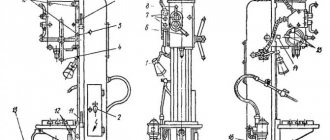
Design and operation of the automatic turret UG 9326
The design of the head is shown in Fig. 2.
The movement from the electric motor (17) built into the sleeve (21) of the housing (23) through a drive coupling made at the end of the rotor shaft (16) and the planetary gear carrier (24) is communicated to the satellite block (12). One of them is mated with a fixed internal gear (26), and the other with a movable gear (9), the hub of which has a trapezoidal thread and a gear coupling at the end. This coupling and screw (3) are used to connect the part (9) to the indexing control cam (4). The radial support of the part (9) is made of bronze half-rings (29), the end ones are the bearings (10) and (11).
Mating with the thread on the part (9) is a flange-nut (8) attached to the spindle (5) of the head, which can perform rotational and translational motion. A tool disk (1) and a locking coupling half (31) with a circular tooth are attached to the spindle. The second coupling half (30) is fixed to the head body.
At the end of the sleeve (21) there is a sensor (13) for the angular position of the tool disk, made on sealed magnetically controlled contacts (reed switches) and connected to the spindle flange via a roller (22) and a coupling (20). The sensor is protected by a casing.
In the niche of the housing there is a set of terminal clamps for the electrical communications of the head, the PC circuit of the engine and a microswitch (14) for controlling the clutch of the coupling halves (30) and (31).
The coolant supply to the tool disk is turned on by pressing the disk on the valve pusher (6), built into the bar (7), attached to the head body.
Head operation
The head operates in a cycle in which the fixed position shown in Fig. 2 is taken as the initial position: removing the force and disengaging the flat-tooth couplings, rotating the tool disk to a given position, preliminary fixing, engaging the couplings and compressing them with the required force.
When the engine starts, the part (9) and the cam (4) begin to rotate counterclockwise. Since the coupling halves (3O) and (31) are engaged and the spindle cannot rotate, due to the interaction of the threads on the part (8) and (9), the coupling half disengages. The end of disengagement marks the contact of the cam shoulder with the finger (35). As the rotation continues, the lock (34), under the influence of the bevels on the part (32), enters the groove on the cam, ensuring the coupling of the drive and the spindle. When the tool disk reaches the required angular position, at the command of the sensor (19), the motor is reversed to, accordingly, the direction of rotation of the head parts is changed. In this case, the clamps (33) and (34) fall into the holes of the flange (32), the cam is released and the drive and spindle are disengaged. With further rotation of the drive, the locking coupling halves are engaged and the necessary tension is created on them, the magnitude of which depends on the installation of the current relay of the motor circuit in the electrical circuit of the machine. The current relay controls the shutdown of the electric motor.
Basic adjustments
The rotation of the spindle should begin after it leaves the clutch of the coupling halves by 0.5 ± 0.2 mm. This value is adjusted by moving the cam along the end teeth of the part (9). A shift of one tooth results in a spindle movement of 0.45 mm.
To properly fix the spindle, it must be overtraveled relative to the given position by 5°…3°. This value is set by turning the sensor (19).
The microswitch (14) must operate 0.5...1.5 mm before the end of the spindle stroke; this is achieved by moving the microswitch bar (13).
Design Features
Grinding heads are a special design that is used to significantly expand the capabilities of a turning group machine. This mechanism conventionally refers to equipment. Design features include:
- the presence of its own electric motor, the power of which can be from 1 kW or more. This point determines that the head can become equipment for various models of lathes. as a rule, turning equipment has a closed gearbox and does not have a separate drive for connecting the equipment in question;
- the installed electric motor is connected to the lathe circuit, which determines the versatility of the entire structure. there is also a three-phase plug for inclusion in a separate power circuit;
- the head has its own frame, which, during modernization, can be rigidly attached instead of a standard tool holder. This point determines that the equipment makes it possible to obtain high-quality surfaces with high mechanization of the process. steel is used in the manufacture of the frame, which helps prevent vibration during operation by increasing the rigidity of the structure;
- rotation is transmitted using a belt drive to reduce speed.
The design is quite simple
When considering it, it is worth paying attention to the type of frame. This is due to the fact that only a certain type of bed can be used instead of a tool holder for a certain model of lathe
Information about the manufacturer of the UG9321 turret head
The developer and manufacturer of the UG9321 turret heads is the Moscow Machine Tool Plant named after. A.I. Efremova and the Gomel Plant of Machine Tool Units GZSU , founded in 1961.
Products of the Gomel Machine Tool Units Plant GZSU
- 2E52
– portable radial drilling machine Ø 25 - 2K52, 2K52-1
- portable radial drilling machine Ø 25 - 2K522
– portable radial drilling machine Ø 32 - 2K550V
– radial drilling machine Ø 55 - 2T118
– vertical drilling machine Ø 40 - 2T125
- vertical drilling machine Ø 25 - 2T140
- vertical drilling machine Ø 40 - 2T150
- vertical drilling machine Ø 50 - GS520
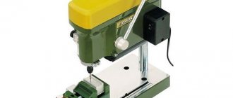
– tabletop drilling machine Ø 16 - GS526U
- universal screw-cutting lathe Ø 500 - GS545
– portable radial drilling machine Ø 45 - GS2112
- tabletop drilling machine Ø 12 - GS2116k
- tabletop drilling machine Ø 18 - 16B20p.061
- apron for screw-cutting lathes - 16B20p.070
— feed box for screw-cutting lathes - UG9321
- 6-position automatic turret head for CNC lathes - UG9326
- automatic 8-position turret head for CNC lathes
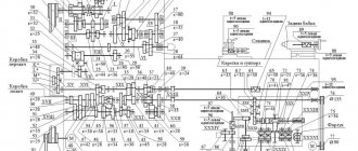
УГ9326 Kinematic diagram of the universal automatic head
Kinematic diagram of the turret head ug9326
On the heads, the tool for centering work is installed using auxiliary bushings in the bores of the tool disk.
Coolant supply is carried out in the working position through auxiliary bushings.
Basic parameters of kinematics elements
- Upper coupling half: number of teeth - 8, Module - 2.25
- Gear wheel: number of teeth - 24, Module - 2.25
- Gear wheel: number of teeth - 30, Module - 2.25
- Gear wheel block: number of teeth - 27, Module - 2.25
- Gear wheel: number of teeth - 33, Module - 2.25
- Gear wheel block: number of teeth - 30, Module - 2.25
- Electric motor 7
УГ9326 Electrical circuit of a universal automatic head
Electrical diagram of the turret head ug9326
The head contains the following electrical equipment:
- M - Asynchronous electric motor model 0.37 kW; 1365 rpm
- S1 - tool head angular position sensor
- 1 — PGK-6 reed switch for head UG9321
- 5 — PGK-10 reed switch for head UG9324
- 6 — PGK-12 reed switch for head UG9325
- 7 — PGK-8 reed switch or UG9324.0200.000 for head UG9326
- 8 — Photo sensor for the head УГ9326-6
- S2 - Microswitch for final clutch clutch control - VP61-21-A111112-00UHL3.2
- RC – RC chain – УГ9321.0200.000
The S1 sensor consists of a cast aluminum housing, a contact device, a permanent magnet flag, a shaft mounted in a plain bearing and covers.
Reed switches are used as switching contacts in the sensor. When the shaft rotates, the magnet passes by the reed switches located in the housing, leading to their alternate activation and release, thereby providing information about the position of the head at any time during rotation of the disk. In this case, the activation zone of the next contact is located behind the release zone of the previous contact, i.e., the contacts operate without overlap.
A block of RC chains УГ9321.0200.000 is connected to the engine