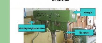
What is a vertical drilling machine 2S132
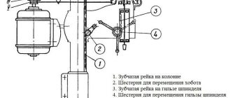
The design of the machine consists of a column located on the base.
The column is a hollow box-shaped casting made of cast iron. along the dovetail column guides. They are moved manually. The lifting table has three T-slots. They hold various devices, such as a vice. Either a floating table or a cross table. An electric pump is installed inside the column on the foundation slab, and an electrical equipment panel is mounted in the niche of the column in the upper part. The base plate contains a coolant reservoir. On the bottom plate there is a plunger pump, thanks to which the gearbox and all parts of the drilling head are lubricated. There is a special oil indicator on the front of the engine plate.
The gearbox shaft supports are located in the upper and lower plates and are fastened together with four ties.
The gearbox communicates 12 rotation speeds to the spindle using movable blocks. And it itself receives rotation from a vertically located electric motor through an elastic coupling and gear transmission.
Switching speeds, as well as switching feeds, is done by handles located on the front of the drilling head.
The feed box is mounted in a separate housing and installed in the drilling head.
The spindle is mounted on two ball bearings.
The drill head is a box-shaped cast iron in which
All the main assembly units of the machine are mounted: speed box, feed box, spindle, feed mechanism, spindle counterweight and speed and feed switching mechanism.
The feed mechanism consists of a worm gear and a rack and pinion gear. The feed mechanism is driven from the feed box and is designed to:
- for manually bringing a tool fixed in the spindle to the part;
- turning on the working feed;
- manual feed advance;
- turning off the working feed;
- manual spindle retraction upward;
- manual feed used in thread cutting.
Careful study of the instruction manual will help you understand how the equipment works.
CNC drilling machine 2р135ф2: characteristics
- The maximum diameter of parts to be processed should not exceed 35 mm.
- The maximum size does not exceed 24 mm.
- The maximum milling width does not exceed 60 mm.
- The processing process involves 6 tools.
- Spindle speed 12.
- The working surface has the following dimensions - 710x400 mm.
- The spindle speed ranges from 35 to 1600 per minute.
- The number of feeds along the Z axis reaches 18.
- Working feeds along the Z axis range from 10 to 500 mm per minute.
- The table and slide move at speeds of up to 7000 mm per minute, and during the milling process 2200 mm per minute.
- The caliper movement frequency reaches 4000 mm per minute.
- In terms of dimensions, the machine has the following parameters: 1800 mm by 2400 mm by 2700 mm.
Design features
The design of the drilling machine consists of:
- The working head, which serves to secure the tool.
- Drive unit.
- Plunger type oil pump.
- Cooling system for the treated area.
- Spindle.
- Gearbox.
- Unit power supply system, electrical cabinet for connecting to the network.
- Gearbox.
- Speed and feed control system.
- Base plate, column, work table.
The unit frame is made in the form of a monolithic, massive, cast-iron structure. The position of the productive surface is carried out by the operator on the supporting column manually, by pressing the locking device and turning the steering wheel, which performs the function of adjusting the position of the spindle. To move the table surface, special guide grooves are made on the column.
The base plate is also cast iron. It has a hollow structure, inside of which there is a container for storing cooling liquid. There is also a settling tank for large metal contaminants and a filtration device. On the support column itself there is an electric pump with a power of 120 W, which is responsible for supplying the liquid. The coolant is supplied through a system of tubes of various diameters, which supply water directly to the drilling element.
The power unit of the machine is located on the top of the body. The spindle block and gearbox of the machine are located in the housing. The kinematic diagram of the equipment has a simple design solution, in which the power unit and the speed box are connected by a straight shaft. Mechanical speed adjustment is carried out using a handle located on the front side of the drilling head. Speed adjustment is done manually. The box transmits spindle rotation speed at twelve frequencies.
The operating elements of the unit are lubricated using a plunger pump in automatic mode. The operator will only need to monitor the oil level using the sensor located on the front panel.
This model has a manual spindle feed system. This system includes:
- A steering wheel that performs an adjustment function.
- Worm-like transmission.
- Overrunning ratchet and dog clutch.
- Limba.
- Shaft, horizontal, with rack and pinion gear.
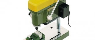
Vertical drilling machine 2S132
The vertical drilling machine 2S132 is designed to perform the following types of work: drilling, countersinking, countersinking, boring, threading in various types of metal and non-metallic parts with high-speed and carbide tools.
Design features of the drilling machine 2S132
- The 2S132 industrial drilling machine has a unit that allows you to control the drilling depth.
- The desktop is equipped with a height adjustment mechanism.
- Electrical equipment is built into the column.
- Coolant supply with tank built into the base.
- Cast iron cast body parts of the 2S132 machine provide high rigidity.
The 2S132 vertical drilling machine allows the use of various devices and tools that expand its technological capabilities.
The 2C132 machine can be used in small-scale production, in small enterprises, and in repair shops.
| Drilling range in steel, mm | 3-32 (50)** |
| Cutting thread range | M3-M33 |
| Table working surface size, mm | 500x500 |
| Number of T-slots | 3 |
| Guide groove width | 18N12 |
| Maximum distance from the end of the spindle to the table, mm | 750 |
| Table lift, mm | 300 |
| Distance from spindle axis to column, mm | 300 |
| Spindle taper | Morse 4 (5)* |
| Spindle quill movement, mm | 250 |
| Number of spindle speeds | 12 (15)* |
| Spindle speed range, rpm | 31,5…1400 (2000, 4000)* |
| Torque, no more, Nm | 400 |
| Axial force on the spindle, no more than, N | 15000 |
| Number of mechanical feeds of the spindle quill | 9 |
| Spindle quill mechanical feed range, mm/rev | 0,1; 0,14; 0,2; 0,28; 0,4; 0,56; 0,8; 1,12; 1,6 |
| Main movement motor power, kW | 4 |
| Installation movement of the drilling head, mm. | 170 |
| Maximum weight of the workpiece, kg | 600 |
| Maximum height of the workpiece, mm | 600 |
| Weight of 2S132 machine, kg (with packaging) | 1500 |
| Weight 2С132 machine 2С132, kg (without packaging) | 1200 |
| Overall dimensions, mm (with packaging) | 1350x1100x2370 |
| Overall dimensions, mm (without packaging) | 870x1110x2700 |
| *optional **at minimum feeds and speeds |
Complete set of machine 2С132:
- Complete machine;
- Handle for lifting the table and drilling head;
- Cooling;
- Lighting;
- Key to email closet;
- Traffic jams;
- Technical documentation (Operation manual).
There are no comments yet, but yours could be the first.
Mark a comment or question There are no reviews yet, but yours could be the first. Leave feedback
Product code: 38899
Drilling machine Stalex VDM-5140
Drilling Ø 40 mm Spindle taper MT4 Spindle reverse yes Max. speed 1400 rpm Power 3.00 kW Voltage 380V Weight 1250 kg
Product code: 39255
Product code: 50153
The manufacturing company reserves the right to change the configuration and place of production of the product without notice! Please note that the information on the site is not a public offer!
Technical characteristics of the machine 2Р135Ф2
| Parameter name | 2Р135Ф2 |
| Basic machine parameters | |
| The largest drilling diameter in steel is 45, mm | 35 |
| The largest diameter of cut threads in steel is 45, mm | M24 |
| The smallest and largest distance from the end of the spindle to the table surface, mm | 40..600 |
| Distance from the axis of the vertical spindle to the rack guides (overhang), mm | 450 |
| Largest cutter diameter, mm | 100 |
| Maximum milling depth, mm | 2 |
| Maximum milling width, mm | 60 |
| Longitudinal movement of the table along the slide guides (X-Axis), mm | 630 |
| Transverse movement of the slide along the bed guides according to the program (Y-Axis), mm | 360 |
| Maximum movement of the spindle head according to the program (Z axis), mm | 560 |
| Caliper. Spindle head. Spindle | |
| Spindle speed, rpm | 45..2000 31..1400 |
| Number of spindle speeds | 12 |
| Speed of rapid movement of the support (spindle head), m/min | 4 |
| Number of caliper feeds along the Z axis, mm | 18 |
| Caliper feed, mm | 10..500 |
| Maximum permissible torque, Nm | 200 |
| Spindle taper | |
| Desktop | |
| Dimensions of the working surface of the table, mm | 400 x 710 |
| Maximum load on the table (center), kg | |
| Number of T-slots Dimensions of T-slots | 3 |
| Speed of rapid movement of the table and slide, m/min | 7 |
| Feed speed of table and slide during milling, m/min | 0,22 |
| Minimum table movement speed, m/min | 0,05 |
| Positioning accuracy of the table and slide along the stroke length, mm | 0,05 |
| CNC system 2P32-3 | |
| Number of controlled coordinates | 3 |
| Number of simultaneously controlled coordinates | 2 |
| Discreteness of setting the movement of the table, slide and support, mm | 0,01 |
| Electrical equipment, drive | |
| Main motion drive electric motor, kW | 3,7 |
| Electric motor for driving the spindle head (support), kW | 1,3 |
| Electric motor for moving the slide and table, kW | 1,1 |
| Electric motor for driving the turret head, kW | 0,75 |
| Electric coolant pump X14-22M, kW | 0,125 |
| Machine dimensions | |
| Machine dimensions, mm | 1800 x 2170 x 2700 |
| Machine weight, kg | 5390 |
- Vertical drilling machine with numerical control 2Р135Ф2-1. Operating manual 2Р135Ф2-1.00.000 РЭ, 1983
- Grachev L.N. Design and adjustment of computer-controlled machines and robotic complexes, 1986, p. 122
- Panov F.S. Working on CNC machines, 1984, p.163
- Barun V.A. Working on drilling machines, 1963
- Vinnikov I.Z., Frenkel M.I. Driller, 1971
- Vinnikov I.Z. Drilling machines and work on them, 1988
- Loskutov V.V Drilling and boring machines, 1981
- Panov F.S. Working on CNC machines, 1984
- Popov V.M., Gladilina I.I. Driller, 1958
- Sysoev V.I. Handbook for a Young Driller, 1962
- Tepinkichiev V.K. Metal cutting machines, 1973
Bibliography
Related Links. Additional Information
- Classification and main characteristics of drilling-milling-boring group of machines
- Selecting the right metalworking machine
- Machine repair technology
- Methodology for checking and testing drilling machines for accuracy and rigidity
- Directory of drilling machines
- Manufacturers of drilling machines in Russia
- Generations of CNC systems. Terms and concepts of CNC systems
- Russian manufacturers of modern CNC systems
- Review of Russian-made CNC systems
- Recommendations for choosing CNC devices
- Problems with modernized CNC machines: tips and tricks from professionals
- Requirements for ensuring stability and safety of machine control systems
Home About the company News Articles Price list Contacts Reference information Interesting video KPO woodworking machines Manufacturers
Safety precautions. Before and during machine operation
Since this unit poses a danger to workers, there is a manual for the 2N135 drilling machine, which contains safety rules:
It is quite important to take care of your overalls. Sleeve cuffs must be buttoned
Hair should be tucked under a beret or scarf. If it is a scarf, then it should be tied so that there are no hanging ends. Safety glasses must be worn. The machine is checked for operability at idle speed. It is important to check all fences and their functionality. The working, as well as auxiliary tools must be inspected to determine whether they are in working order or not. It is necessary to check the serviceability of the protective element.
There are also rules that must be followed while working:
- The cutter and the workpiece must be securely fastened.
- You cannot put anything on the machine, or lean on it.
- During work, it is forbidden to be distracted by extraneous conversations and so on.
- The belt, cutter and other working parts of the machine must not be grabbed.
- Do not move away from the device unless it has been stopped first.
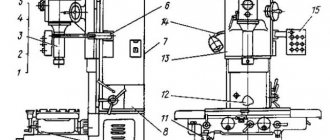
General view and controls of the drilling machine 2N118
Drilling machine controls 2n118
Specification of controls for drilling machine 2N118
- Light switch
- Cooling pump switch
- Input circuit breaker
- Feed mechanism control handle
- Mechanical feed button
- Feed shift knob
- Push-button station “Right”, “Left”, “Stop”
- Gear shift knob
- Drill head clamp handle
- Bolts for adjusting the wedge of the drill head
- Table Clamp Handle
- Bolts for adjusting the table wedge
- Table lift handle
- Drill head lifting mechanism roller square
- Cycle adjustment cams
- 3/4″ hole for connecting the machine to the electrical network
Device design and features
The device of this type of unit includes the following elements:
- spindle;
- gearbox;
- base, workplace and column;
- drive unit;
- head for securing the tool;
- electrical cabinet;
- cooling system;
- gearbox;
- system that controls speeds and feeds;
- plunger oil pump.
Plunger oil pump
For vertical drilling machines, the technical characteristics indicate their versatility. These devices can perform not only drilling, but also countersinking, reaming, threading and reaming of holes.
This is due to the use of durable and hard tools made from well-cutting steels.
The main features of the device are as follows:
- machine weight - 1199 kg;
- spindle torque can reach a maximum of 399 Nm;
- presence of a spindle stop system;
- the maximum permissible force at which the feed is performed is 15 kN;
- the use of an electric pump of the X14-22M type as part of the structure to transfer the cooling liquid to the processing site;
- The dimensions of the desktop are 449*499 mm, on the surface of which there are three grooves in the shape of the letter “T”.
One of the main technological features of the machine is its 100% manual control. All stages of work are adjusted manually, and the spindle feed is carried out mechanically.
General characteristics of the unit include three large parts:
- workplace-table on which the part to be processed is located;
- stable cast iron frame with space inside for electrical equipment;
- a drilling head with a spindle that moves vertically using a worm shaft.
2R135F2 machine characteristics
Buy this machine without intermediaries:
Specifications:
Machines model 2р135ф2 are designed to perform the following operations: drilling, countersinking, reaming, countersinking, reaming, threading, light straight milling.
Maximum drilling diameter in steel 45 GOST 1050-74, mm 35 Spindle cone dimensions according to ST SEV 147-75 Morse 4 Spindle cone dimensions for milling Cone 7:24 Maximum milling width, mm 60 Maximum milling width, mm 2 Maximum spindle stroke, mm 250 Distance from the end of the spindle, mm: to the table 600 Maximum (installation) movement of the drill head, mm 170 Working surface of the table, mm 400x710 Maximum table stroke, mm 630 Number of spindle speeds 12 Number of feeds 9 Feed limits, mm/rev 0.1- 1.6 Maximum height of the workpiece, kg 300 Machine dimensions: length, width, height, mm 1860x2400x2700 Machine weight, kg 4700
Buy this machine without intermediaries:
mashinform.ru
Vertical drilling machine 2s132
photo: kinematic diagram of a vertical drilling machine 2S132
- photo: electrical diagram of a vertical drilling machine 2S132
- photo: electrical diagram of vertical drilling machine 2S132 continued
Stand for vertical drilling machine 1s132
The stand is a hollow cast iron on which the drill head and table move along dovetail guides. The table has three T-shaped slots in which various equipment is secured.
An electric pump for coolant is installed on the foundation slab, and a cabinet with electrical equipment is mounted in the upper part of the column.
The base plate serves as a reservoir for the cooling lubricant.
The gearbox is designed to carry out the main movement - spindle rotation. The rotation of the input shaft of the gearbox is carried out from the electric motor through an elastic coupling 10 and a gear drive.
Using moving blocks 5, 7, 8, the spindle is given from 12 to 15 speeds. The output shaft 2 of the gearbox has a splined hole through which torque is transmitted to the spindle.
Through gear 3, the rotational movement is transmitted to the feed box.
photo: gearbox of vertical drilling machine 1s132
The feed box is installed in the drilling head and is designed for axial movement of the spindle. Nine innings are carried out using two triple moving blocks.
The output shaft of the feed box is centered with the upper support of the feed worm. A half-coupling is located on the shaft, transmitting rotational motion to the worm of the feed mechanism.
photo: feed box of vertical drilling machine 1s132
The spindle head 2 is mounted on two bearings, the axial load is perceived by the lower thrust bearing, and the force when knocking out the cutting tool is taken by the upper ball bearing. The bearings are located in the quill 3, which moves along the axis using a rack and pinion transmission.
The tool is knocked out of the Morse taper of the spindle using a special device on the spindle head. Knockout is performed by rotating the steering wheel by hand while lifting the spindle head. The holder 5 of the special device rests against the body of the drilling head and the lever 4, turning around the axis, knocks out the cutting tool.
The lower groove of the spindle is designed for fixing the mandrel with a cutter installed in it using key 7 when processing planes on the 2S132PF2I machine! From the key falling out of the groove during milling, the key is protected by a quick-change bushing, used only during milling and installed in the grooves of the cup 6.
photo: spindle of vertical drilling machine 1s132
Floating table of vertical drilling machine 1s132
The floating table is designed for drilling parts using a copier or marking and consists of the following parts: table 1, slide 2 and base 3.
The table moves along the slide in the longitudinal direction on needle bearings. The slide with the table, in turn, moves in the transverse direction also on needle bearings. Roller needle bearings provide ease and smooth movement and set the table in the desired position.
- A clamping device consisting of an eccentric shaft 4, upper and lower rods 5 and 6, as well as two wedges 7 fixes the table in the desired position.
- The clamping device is adjusted using a screw.
- During the operation of the table, there is a need to adjust the rolling guides to create the necessary tension between the guides and the rollers.
| Maximum height of the workpiece, mm | 800 |
| Maximum weight of the installed workpiece, kg | 600 |
| Largest drilling diameter, mm | 32 |
| Drilling diameter limits, mm | 3…35 |
| Dimensions of the working surface of the table, mm: | |
| width | 500 |
| length | 500 |
| Dial division price, mm | 0,05 |
| Maximum manual spindle movement, mm | 250 |
| Number of spindle speeds |
Kinematic diagram of the drilling machine 2Р135Ф2-1
Kinematic diagram of the drilling machine 2р135ф2-1 with CNC 2П32-3
The kinematic diagram of the machine (Fig. 4.6) consists of the following independent kinematic chains: main movement drive (rotation of the turret spindles); cross table feed drive; caliper drive with turret head; turning the turret head; pressing tools out of spindles.
Main movement chain
Main movement chain: two-speed asynchronous electric motor M1 (N = 4/4.5 kW; n = 1470/990 rpm) - 29/41 gear transmission - shaft I - shaft II (through gears 24/48 and 36/36 at engaged couplings M1 and M2 or through gear 14/36 with engaged coupling M3) - shaft III (via gears 14/36 and 48/24 with engaged couplings M4 and M5) - shaft V through bevel gear 21/21 - to one of turret spindles through 35/42 gears; 31/49; 49/47; 47/35.
Cross table feed drive chain
The feed drive chain of the cross table has two gearboxes, one of which moves the table along the slide (X-axis), and the second drives the movement of the slide along the frame (Y-axis).
Kinematic chain of the slide drive
The kinematic chain of the slide drive ensures their fast, medium and slow movements. Fast movement (at a speed of 7000 mm/min): M4 electric motor (N=0.6 kW; p=1380 rpm) - 16/40 gears; 34/22; 22/52; 52/34 - ball screw.
Moving at medium speed (200 mm/min): M4 electric motor - 16/64 gears; 25/55; 25/55; 38/42; 22/52; 52/34 - ball screw. Slow movement (at a speed of 50 mm/min): M4 electric motor - 16/64 gears; 25/55; 25/55; 16/64; 22/52; 52/34 - ball screw. A feedback sensor is mounted on the ball screw.
The table moves along the slide from the M5 electric motor (N = 0.6 kW; n = 1380 rpm); the kinematic chain of the drive of this movement is similar to the kinematic chain of the drive of the slide movement.
Turret Caliper Drive Chain
Caliper drive chain with turret head: DC electric motor M2 (N = l.3 kW; n = 50..2600 rpm) - 13/86 gear (or 37/37 gear - 4/25 worm gear - lead screw, equipped with a brake clutch (preventing arbitrary lowering of the caliper when the electric motor is turned off) and a remote control feedback sensor.
Turret rotation drive chain
Turret head rotation drive chain: M3 electric motor (N=0.7/0.9 kW; n= 1400..2700 rpm) - 23/57 gear - 1/28 worm gear - 16/58 gear - turret body .
Pressing tools out of spindles
Pressing tools out of spindles: M3 electric motor - 18/52 gear (with the clutch engaged) - 1/28 worm gear - 21/21 gear - eccentric mounted in the groove of the turret head rotation axis and pressing tool.
Lubricating the turret support
Lubrication of the turret head support is carried out forcibly according to the following scheme: MZ electric motor - 18/52 gears; 52/75 - EZ eccentric, driving the plunger pump.
Gearbox lubrication
The gearbox is lubricated by a gear pump driven by the gearbox electric motor through a V-belt. The oil supplied by the pump enters the distribution chamber, where it is distributed to lubricate all moving parts of the gearbox and electromagnetic clutches, and then drained into the reservoir. The oil level is controlled by an oil indicator.
Lubrication of caliper feed gearboxes and cross table
Lubrication of the caliper feed gearboxes and the cross table is carried out by spraying oil onto the gears. The oil level is monitored visually using oil indicators.
Lubricating the guides and screw pairs of the cross table
The guides and screw pairs of the cross table are lubricated manually using a lubricator. The bearings of the turret spindles are lubricated with grease.
Coolant supply
The coolant is supplied from a centrifugal pump. To cool the tool in the cutting zone, an individual drive is provided, which allows you to direct a stream of coolant to the desired location. The supply of coolant in the automatic cycle begins when the caliper moves down (the beginning of the working feed) and stops when the caliper begins to return to its original position (in this case, the corresponding toggle switch must be turned on on the control panel).
Electrical equipment of the machine
The electrical equipment of the machine consists of a separate cabinet of relay automation and CNC, as well as elements installed directly on the machine. Electrical connections between the machine components and the CNC are made by harnesses in metal hoses ending with connectors.
The electrical circuit of the machine provides the following operating modes:
- commissioning;
- semi-automatic with task input from CNC switches;
- semi-automatic with task input from punched tape;
- automatic with task input from punched tape.
The mode is selected using switches located on the control panels of the machine and the CNC.
Information about the manufacturer of the vertical drilling machine 2N135
The manufacturer of drilling machines models 2N125, 2N135, 2N150, 2G175 is the Sterlitamak Machine Tool Plant, founded in 1941.
The history of the Sterlitamak Machine Tool Plant begins on July 3, 1941, when the evacuation of the Odessa Machine Tool Plant to the city of Sterlitamak began.
Already on October 11, 1941, the Sterlitamak Machine Tool Plant began producing special modular machines for the defense industry.
Currently, the plant produces metalworking equipment, including CNC lathes and milling machines, multifunctional machining centers, metalworking and cutting tools.
Operating procedure on the machine
Setting up the machine for operation consists of installing the table and drilling head in the positions required for operation, clamping them on the column, and setting the required rotation speeds and spindle feeds.
The 2S132PF2I machine provides the following control modes:
- adjustment (manual control from buttons);
- automatic (control from DRO K524);
- semi-automatic (positioning of the table according to the program from the DRO device, and the approach and removal of the quill with the spindle manually).
To establish the adjustment mode, it is necessary to set the “Mode selection” switch on the machine control panel to the “Adjustment” position.
Working on the machine in the “Adjustment” mode is carried out by pressing the corresponding buttons on the control panel.
To select the movement axis, use the “Select X and Y axes” switch. To move the table in positive and negative directions, use the “Positive direction of movement” buttons, respectively. To control the direction of spindle rotation, use the “Spindle rotation to the left” buttons on the control panel.
To rotate the gears in the gearbox when switching spindle rotation speeds, use the “Spindle Rotation” button.
The 2S132TS machine provides the following control modes:
- manual mode;
- auto.
In manual mode, set the “Mode selection” switch to the middle position “Manual mode”. The machine is controlled by pressing the corresponding buttons on the machine console “Spindle rotation to the left”, “Stop”. The working feed is carried out both from the steering wheel and using a mechanical transmission from the main movement electric motor.
In automatic mode, set the “Mode selection” switch to the extreme left position “Drilling”. Set the cams depending on the processing depth. Using the steering wheel, move the spindle to the upper starting position. Press the “Start cycle” button.
Automatic thread cutting
ATTENTION! Thread cutting with an automatic spindle feed cycle is possible only for machines 2S132PFI and 2S132Ts. Feed ranges are shown in table
10.
During the automatic thread cutting cycle, set the “Mode selection” switch to the extreme right position “Thread cutting”. Set the cams depending on the processing depth. Press the “Start cycle” button. The end of thread cutting on the 2S132Ts machine is controlled by the corresponding cams on the dial, and on the 2S132PF2Y machine according to a given program.
The following modes are provided on the 2S132K and 2S132 machines:
- manual spindle feed;
- mechanical spindle feed.
Set the cams depending on the processing depth.
After turning on the rotation and feed of the spindle, processing of the part begins. When the desired machining depth is reached, the spindle feed will stop and the spindle will continue to rotate. To stop it, you need to press the “Stop” button.
When cutting threads on a machine with spindle reverse at a certain depth, set the dial on the drilling head so that the number corresponding to the processing depth is opposite the pointer. Align the cam mark “P” with the corresponding mark on the dial and secure the cam. Turn off mechanical feed. After turning on the spindle, manually insert the tap into the hole. After 2-3 spindle revolutions, there is no need for manual feed. When the specified cutting depth is reached, the spindle is automatically reversed and the tap exits the hole. In order for the spindle to rotate to the right, you need to press the corresponding button.
Vertical drilling machine mod. 2р135ф2
This Computer Numerical Control (CNC) machine is designed for drilling, countersinking, reaming, threading, face trimming, etc. in low to mid-volume production. The presence on the machine of a six-position turret for automatic change of cutting tools and a cross table with program control will create the ability to carry out coordinate processing of parts such as covers, flanges, panels and other parts without preliminary marking and without the use of jigs, machine accuracy class N.
Numerical control system. Machine mod. 2Р135Ф2 is equipped with a numerical control device “Coordinate S70-3”, which ensures simultaneous movement of the table along the X and Y axes when positioning the movement control along the axis (from the coordinate), makes it possible to control the rotation of the turret, select the value of the working feed and spindle speed. The device has a digital display and allows for input of corrections for tool length.
The positional rectangular CNC system is closed; code converters are used as measuring devices. The positioning accuracy of the table and support is 0.05 mm, the discreteness of programming and digital display is 0.05 mm. Number of controlled coordinates: total - three; simultaneously - two.
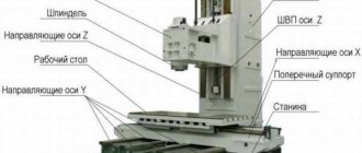
A column is mounted on the base of the machine, along the rectangular vertical guides of which a support carrying a turret head moves. The gearbox and feed reducer are rigidly mounted on the column. The cross table has a base along which the slides carrying the table itself move in the transverse direction. The latter, in turn, can move in the longitudinal direction along the slide guides. The movement of the slide and table is carried out from the gearboxes.
Rotate the turret head. The head rotates using the following kinematic chain. From the MZ electric motor (0.7/09 kW, 1400/2700 rpm) through the shaft transmission to the shaft, from which the worm gear transmits the movement to the shaft and transmission, which rotates the turret head. The clutch must be engaged. Before turning the turret, it must be unlocked, since it is secured by spring-loaded caliper rods located in the grooves of the turret. When the shaft on which the worm sits rotates, it has the ability to move axially, so it turns out of the worm wheel and, moving down through the rack and pinion gear with the wheel and the module, turns the shaft with an eccentric, which will release the turret with a system of levers; at the same time, the second rack wheel moves the rack on the shaft and thereby disengages the wheel on the shaft. Thus, the turret head is released and the kinematic chain connecting the rotation drive to the turret spindle is broken. After this, the worm reaches a hard stop and begins to rotate the turret by means of a transmission, changing the tool (direct rotation).
Simultaneously with the rotation of the turret head through the transmission, the shaft and gear rotates a positional command device on the shaft, which stops the direct rotation of the turret head by reversing the electric motor, having previously reduced its rotation frequency to 1400 rpm. During reverse rotation, the turret reaches the hard stop of the caliper and stops; at the same time, the worm, turning out of the worm wheel, moves upward. The shaft rotates in the opposite direction, the gear engages with the turret spindle wheel. The head is fixed and the spindle begins to rotate. The choice of the operating sequence of the turret spindles is set on the console. There are six processing cycles in total.
The table moves from the M4 engine (0.6 kW, 1380 rpm). The table gearbox does not differ from the sled gearbox, therefore, its kinematic diagram does not indicate shafts and wheels.
Thread cutting. For cutting threads with a machine tap, chucks are used that can be installed in any position of the turret. When cutting threads, use a copier, a screw-nut in steps of 1.0; 1.25; 1.5; 1.75; 2.0; 3.0 mm, set of replaceable collets for fastening taps, adapter squares. The threading head has a mechanism for adjusting the operation of the head in the cycle forward (threading) - reverse (unscrewing the tap after cutting the thread). The full cycle of work with the support is provided by the electrical circuit of the machine. Rotation from the spindle is transmitted through a liner inserted into the spindle of the turret head, through a gear coupling to the driver, spline shaft and collet.
www.4ne.ru
Operating principle
Operation of the machine in operating mode occurs according to the following principle. The workpiece to be processed must be installed and securely fixed on the working surface of the coordinate table. The spindle with the installed tool should be located in the lowest position. Using the worktable longitudinal displacement system, the spindle must be centered.
Then you need to make sure that the end of the part to be processed and the spindle are coaxially positioned. Based on the kinematic possibilities, in the high-speed gearbox we select the rotation speed suitable for processing. We turn on the vertical electric motor of the main drive.
After setting up the kinematic diagram, the tool head moves to the end of the workpiece, and the desired technological operation is performed.
Brief description of the components of the machine 2S132, 2S132K, 2S132Ts, 2S132PF2I
The machine column is a hollow box-shaped cast iron casting. A drilling head and a lifting table with three T-shaped slots, in which overhead cross tables are fixed, are manually moved along the dovetail column guides: mechanized - on a mod. 2S132PF2I, floating with manual control - on a machine mod. 2S132K. An electric pump is installed on the foundation slab, inside the column. The base plate serves as a reservoir for the coolant.
The drilling head is a box-shaped cast iron in which all the main assembly units of the machine are mounted: speed box, feed box, spindle, feed mechanism, spindle counterweight and speed and feed switching mechanism.
The feed mechanism is driven from the feed box and is designed to perform the following operations:
- Manual or automatic approach of a tool fixed in the spindle to the part;
- Manual feed advance;
- Manual or automatic spindle retraction upward;
- Manual feed used in thread cutting.
The overhead mechanized cross table is designed to move the workpiece installed in a fixture on the working surface of the table in the longitudinal (along the X axis) and transverse (along the Y axis) directions.
The mechanized cross table provides fast movements, positioning in specified coordinates, as well as working feed of the workpiece for easy straight-line milling.
The table contains drives for the longitudinal movement of the table along the slide guides, the transverse movement of the slide along the base guides, as well as the protection of the longitudinal and transverse guides.
The floating table is designed for processing parts using a copier or marking and consists of three main parts: a table, a slide and a base.
The table moves along the slide in the longitudinal direction on roller needle bearings. The slide together with the table moves transversely on the same roller needle bearings. Roller needle bearings make it easy to move and set the table into the desired position.
Modifications of drilling machines 2С132
To process holes of different diameters, basic vertical drilling machines of the following models are used: 2С132. The last two digits of each model number indicate the largest hole diameter in mm that this machine can drill into 45 steel workpieces.
Based on the above basic machine models, the following modified models were created:
- 2N132 - basic model of a vertical drilling machine;
- 2D132F11 - vertical drilling machine with a digital display device;
- 2С132 (SB50) - basic model of a vertical drilling machine;
- 2S132L (SB50R) - vertical drilling machine on a round column;
- 2S132K - coordinate vertical drilling machine with a floating cross table;
- 2S132PF2I - coordinate vertical drilling machine with a floating cross table and digital control (CNC);
- 2С132Ц, 2С132ЦП - vertical drilling machines with automated control (control is carried out using pre-configured cams and buttons);
Vertical drilling machine 2р135ф2
Figure 28 - General view and working area of a vertical drilling machine
2Р135Ф2
Vertical drilling machines are designed for drilling, reaming, countersinking, reaming and threading parts such as covers, flanges, panels, etc. without preliminary marking and without the use of conductors.
The cross table works automatically according to the dialed program. The spindle movement cycle is automated. The machines can be used in small-scale and mass production.
Machine mod. 2Р135Ф2 is equipped with a cross table and a six-position turret, which significantly expand its technological capabilities and allow it to be successfully used in single, small-scale and mass production of parts.
Specifications:
| Maximum drilling diameter, mm | 35 |
| Maximum diameter of cut threads, mm | 24 |
| Drill head stroke, mm | 250 |
| Table dimensions, WxD, mm | 400×630 |
| Spindle speed range, rpm | 31,5-1400 |
| Spindle feed range, mm/min | 10-500 |
| Spindle taper dimensions (Morse) | 4 |
| Fast table retraction and approach, mm/min Number of tools | 3800 6 |
| Number of controlled coordinate axes (total / simultaneously) | 3/2 |
| Feed drive power along coordinate axes, X/Y/Z, kW: | 0,3/1,3/1,3 |
| The distance from the end of the spindle to the table is greatest, mm | 560 |
| Number of feed stages along the coordinate axes X, Y, Z | 18 |
| Maximum length of movement along coordinate axes, X/Y/Z, mm: | 560/360/560 |
| Readout resolution along coordinate axes X', Y', Z', mm | 0,005 |
| Number of main motion drive speeds (total/according to program) | 12/12 |
| Digital indication of Position, block no., CNC tool no. | Positional rectangular, type “Coordinate C70-3” |
| Code | ISO-7bit |
| Software carrier | Eight-track punched paper tape |
| Machine accuracy class | N |
| Main motion drive electric motor power, kW | 4 |
| Overall dimensions of the machine, LxWxH, mm | 2500x1800x2700 |
| Machine weight, kg | 3500 |
Model 100cn grinding machine
Figure 29 — Model 100 CNC grinding machine
Figure 30 - Model 100 CNC Grinder (without guard)
Figure 31 — Processing area on the machine mod. 100 CNC with automatic loading/unloading device
Figure 32 - Machining scheme using a turret with two grinding spindles
Grinding machine mod. The 100 CNC is designed for processing small parts in large quantities.
The machine is equipped with one or two spindles (with parallel axes). Available only with automatic loading/unloading devices.
Brief technical specifications:
| Machine model | 100 CNC | 100 CNC T | |
| Diameter of grinding holes | From 1 mm | from 1 mm | |
| Maximum dimensions of grinded parts (diameter) | When mounted in a chuck | 60 mm | 60 mm |
| For centerless grinding | 40 mm | 40 mm | |
| When clamping a part in a chuck | Max chuck diameter | 150 mm | 150 mm |
| Programmable speed, | 0-2000 min-1 | 0-2000 min-1 | |
| Drive power | 2 kW | ||
| Maximum axial clamping force | 2500 N | 2500 N | |
| Maximum total weight of clamping device with workpiece | With a spindle end diameter of 100 mm | 30 kg | 30 kg |
| X and Z axes | Working stroke | 130 mm | 130 mm |
| Permission | 0.1 µm | 0.1 µm | |
| Maximum travel speed | 10 m/min | 10 m/min | |
| Center height | Above the table with detail | 110 mm | 217 mm |
| Above the table with the grinding wheel | 90 mm | 197 mm | |
| Overall dimensions of the machine | (Length x Depth x Height) | 1500x1500x2060 mm | 1500x1500x2060 mm |
| Machine weight | 2000 kg | 2000 kg |
Main technical characteristics of Voumard VMX series spindles:
| Spindle type | Rotation speed, min-1 | power, kWt | Outer diameter, mm |
| VMX 06 | 3 — 6000 | 7 | 150 |
| VMX 7.5 | 5 — 7000 | 7 | 150 |
| VMX 15 | 9 — 15000 | 8 | 150 |
| VMX 30 | 20 — 30000 | 8 | 150 |
| VMX 40 | 33 — 40000 | 7 | 150 |
| VMX 65 | 42 — 60000 | 4 | 120 |
| VMX 90 | 60 — 90000 | 3 | 90 |
| VMX 120 | 90 — 120000 | 2 | 90 |
VMX spindles are designed for use with standard 14 kVA drives.
The VMX 06 spindle is designed for grinding flat faces or for external cylindrical grinding with a flat wheel with a diameter of 250 mm.
Other more powerful grinding spindles can be supplied upon request.
Areas of use
- Automotive industry
- Mechanical engineering
- Aerospace
- Machine tool industry
- Instrument industry
studfiles.net
Information about the manufacturer of the vertical drilling machine 2Р135Ф2
The manufacturer of drilling machines models 2Р135Ф2, 2Р118Ф2, 2Н125, 2Н135, 2Н150, 2Г175 is the Sterlitamak Machine Tool Plant, founded in 1941.
The history of the Sterlitamak Machine Tool Plant begins on July 3, 1941, when the evacuation of the Odessa Machine Tool Plant to the city of Sterlitamak began.
Already on October 11, 1941, the Sterlitamak Machine Tool Plant began producing special modular machines for the defense industry.
Currently, the plant produces metalworking equipment, including drilling and honing machines, CNC lathes and milling machines, multifunctional machining centers, metalworking and cutting tools.
Products of the Sterlitamak Machine Tool Plant
- 2135
— universal vertical drilling machine Ø 35 - 2A125
- universal vertical drilling machine Ø 25 - 2A135
- universal vertical drilling machine Ø 35 - 2A150
- universal vertical drilling machine Ø 50 - 2G175
- universal vertical drilling machine Ø 75 - 2N125
- universal vertical drilling machine Ø 25 - 2N135
- universal vertical drilling machine Ø 35 - 2N150
- universal vertical drilling machine Ø 50 - 2R135F2
- CNC vertical drilling machine Ø 35 - 2S125, 2S125-1 (2S125-01), 2S125-04
- universal vertical drilling machine Ø 25 - 2S132, 2S132K
- universal vertical drilling machine Ø 32 - 2С150ПМФ4
- vertical drilling-milling-boring machine with CNC and ASI 500 x 1000 - 400V
- vertical drilling-milling-boring machine with CNC and ASI 400 x 900 - SF-16, SF-16-02, SF-16-05
- tabletop milling and drilling machine Ø 16
2Р135Ф2 vertical drilling machine with CNC. Purpose and scope
Vertical drilling machine 2Р135Ф2 with a six-spindle turret head, with a cross table and numerical control (CNC) is designed for drilling, reaming, countersinking, reaming, threading and milling in small-scale and mass production of various industries.
The 2R135F2 drilling machine is used for processing body parts and parts such as “flange”, “cover”, “plate”, “lever”, “bracket”.
The electrical circuit and CNC make it possible to carry out the following technological operations on the machine:
- Drilling;
- End trimming (countering);
- Boring;
- Threading;
- Deep drilling;
- Milling.
Where is the 2r135f2 CNC drilling machine used?
The machine in question is used to regulate the process of rectangular machining and positioning. The program carrier is a punched paper tape with eight tracks. The machine is equipped with a digital display; up to 15 adjustments per tool length can be entered.
The machine has a closed system in which the BS155A selsyn acts as sensors. The table and slide are positioned with an accuracy of up to 0.02 mm, digital display and movement assignments have a resolution of up to 0.01 mm. There are a total of 3 controllable coordinates, 2 of which can be used simultaneously.