18.03.2020
- General information
- Purpose
- Flat cutting software
- Programs for metalworking and woodworking CNC machines for 3D models
- Specialized software
- Program capabilities
- The process of developing programs for CNC machines
- CNC development
- Software debugging
- Video
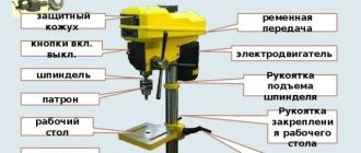
The presence of a numerical control panel in the equipment significantly speeds up and simplifies the metal and woodworking production process for the operator. But he is required to have more training and understanding not only of the mechanics of cutting (milling, turning), but also of the software and computer side of the issue. Today in the article we’ll talk about writing control programs for a CNC milling machine for wood and metal.
General information
At the beginning of the 20th century, all devices for processing workpieces were mechanical. That is, of course, there was an electric drive, but the movement of all components was monitored by a mechanic. This is a rather complex and honorable activity; mastering it requires specialized education, as well as significant skill and experience. But classic models have a number of disadvantages:
- They are not accurate enough. To achieve a high level of accuracy, hard, meticulous work is required, as well as the impeccable condition of both the equipment itself and all the cutters - no vibrations or accidental movements.
- A large number of errors and defective parts due to the human factor. Little experience or poor communication (it’s not for nothing that all turners have ranks), fatigue, simple inattention - and the whole workpiece goes to waste. This is not economically viable.
- Hard physical labor. Each piece of equipment must have a mechanic who is involved in many operations - from securing the metal in a vice to operating the cutter. This is constantly intense work that requires attention, strength and, we repeat, experience.
- Poor performance. The metal processing speed is not high enough because everything is done manually.
Along with the first creation of programs for CNC machines, the realization emerged that the same amount of work could be done faster, without errors, with minimal human resources.
For the first time in the USSR, software-controlled systems were introduced during the Great Patriotic War, during the same period the first problems appeared - insufficient competence of technical personnel, little knowledge of the basics of programming and imperfect equipment.
It became possible to correct this problem with the advent of sufficiently user-adapted working computer environments. Let us explain with an example how this is interconnected.
An engineer wants to create a metal assembly. Doing it manually is very difficult, almost impossible, so he first goes into the software. Here it performs two overlapping operations:
- Complex mathematical calculations that are aimed at checking the functionality of the node.
- Drawing.
Then the specialist, having completely completed the first task, changes the format of the document and ends it in a digital equipment control panel.
Now his job is small - place the workpiece, observe the correct execution of the process, and then remove and check the sample. And the built-in program for CNC milling will automatically select the appropriate speed and cutting angle, mode, as well as the most efficient movement algorithm.
So, to create any complex three-dimensional part from metal, wood, or other material, you need to use computer software with 3D graphics capabilities. Then the image needs to be converted into g-code. It is important that the software matches the operating system, that is, the OS “pulls” the program. For example, most professional CAD does not work correctly on the usual Windows, but will work on Linux. Convenience (mostly the absence of delays, which is very important) also depends on the personal computer itself.
What are the G and M CNC codes: description
First, let's determine what the difference is between them. The GI teams are the main and preparatory teams, the EM teams are auxiliary (technological). They are written down together, in a line (the first ones at the beginning, the second ones at the end) or, in other words, frame by frame - for clarity of listing. As a result, the algorithm is a collection of character blocks - with addresses and numeric values.
The tasks of the G-group include determining the linear or circular speed, as well as the direction of movement of the working tools of the equipment. In addition, they are required to regulate boring and threading, manage coordination and other features of additional equipment.
CNC programming M-codes are designed to complement the basic ones, simplifying the execution of the algorithm. In practice, their role is reduced to changing blades, drills (or other organs), calling and terminating subroutines.
Besides these two common families, there are also:
- S-commands that determine the specifics of the main movement.
- F, responsible for the nature of the feed.
- D, H, T, expressing the key parameters of the hanging elements.
Therefore, it is extremely important for the operator to understand the variety of symbols presented, and the ability to read them line by line is generally implied - this is a necessary condition for monitoring the execution of technological operations.
Purpose
First, let us note in several advantages why such machines themselves are needed:
- They increase the efficiency and productivity of the entire enterprise several times.
- Reduce the likelihood of a defective sample.
- They take most of the load off the operator, leaving him with simpler work.
- Increases the accuracy of the workpiece.
And in order for such a system to be possible, a program is simply necessary. The main task of creating specialized software is to enable the miller (turner) to be distracted from the process and reduce his responsibility for the result. Now he is not obliged to continuously monitor every movement of the cutter and drill. Thus, the software includes a set of commands that together arrive at the equipment and influence what process is being performed.
Thus, commands automate a number of actions:
- Selecting a tool, its fastening.
- Fixing and centering the workpiece.
- Determining the appropriate mode and cutting speed based on the parameters of the material and cutter.
- Movement of the cutting edge. Moreover, the minimum, optimal distance is determined depending on the coordinates in which the “zero” point becomes the final position of the cutter. That is, there is no need to always return to the initial section before the next pass.
For each new element, it is necessary to write a new code (drawing), which requires specialized software. If you have it, and you also have basic communication skills with a graphic editor, you can easily create new commands for equipment.
Command parameters specified in Latin letters
| Symbol | Description |
| Coordinates of points along the corresponding axes | |
| X | |
| Y | |
| Z | |
| Speed | |
| F | working feed |
| S | spindle rotation |
| R | radius (or, less commonly, standard cycle indicator) |
| I, J, K | dimensions of the arc observed in the case of circular interpolation |
| D | correction of the current tool |
| P | delay (or number of subloop calls) |
| L | subroutine by label |
Flat cutting software
2D design is an easier task for the carver. The main process performed on this equipment is cutting materials. From classic sawing of wood or metal, you can move on to more complex, shaped designs. This can be done especially quickly and conveniently using a plasma cutter. But, as with other elements, it is necessary to use a control program for working on CNC machines with a wood or metal milling machine in a plane. ArtCAM is suitable software for this task. The project itself was created in 2003, and since then it has only been gaining popularity. The advantages include:
- The ability to work in 3D, that is, for various workpieces you will not need to choose other software.
- Saving previously prepared models.
- Their integration into the assembly.
- Import in all major formats used in CAD, and also, of course, suitable for CNC machines.
- The “magic wand” option makes selecting and highlighting the work area much easier.
- Reduced command processing time on woodworking and metalworking equipment.
- Ability to move, rotate or copy the motion path.
- Built-in feed optimization.
- Simple interface and easy to learn.
In addition to Artkam, they use VISIO-2007 and Vectric 2dcut, Mach3. The latter has the advantage that it can be used on a familiar operating system – Windows. And the greatest experts, who already draw “with their eyes closed,” generally say that you can make a simple cutting in the usual built-in “Notepad”, and then translate it all into command code.
Why you should learn CNC programming
The answer is obvious - to be able to write optimal algorithms for performing a specific technological operation. Simply understanding commands and using ready-made solutions is not always convenient - for the following reasons:
- Standard options almost certainly do not take into account the specifics of production - in order to optimize they need to be adapted, and this is extremely difficult to do without knowledge of the ISO 7 bit language.
- Methods are constantly being improved, so it is necessary to keep up with them, because the sequence of actions that was relevant a year ago may already be morally outdated today.
- The process of managing the production of parts needs to be streamlined - by reducing the number of personnel, combining repetitive cycles and other ways to simplify listing, which can only be implemented by a well-versed operator.
Programs for metalworking and woodworking CNC machines for 3D models
Most modern software has tools for working with volumetric parts. Creating three-dimensional models is also called prototyping, that is, preparing a prototype. We list the professional software that is used by specialists:
- CADDS5;
- PowerShape;
- SolidEdge;
- T-Flex CAD;
- AutoCAD.
Almost everywhere in the name the combination CAD flashes; in Russian the abbreviation is translated as CAD or computer-aided design system. All of the above software are united by the fact that they have the ability to solid-state design, that is, one that completely simulates working with a real sample, be it metal, wood, plastic and others. After modeling, you can make detailed visualizations, as well as a test run of the model. And only after that proceed to creating parts on equipment. Advantages of using this software:
- Maximum realism is useful when you need to present your project.
- It's easy to adjust the code if mistakes are made or plans change.
- Automatic generation of drawings.
- Ability to use templates.
- A minimum amount of time is spent.
G-codes for CNC: table of preparation commands
| Symbol | Description |
| G00-04 | setting the tool in position |
| G17-19 | switching between planes – XY, XZ and YZ, respectively |
| G20-21 | calculations in English (inch) or metric measurement systems |
| G40-44 | compensation of length, diameter, dimensions of the working body |
| G53-59 | transition from one coordinates to others |
| G80-84 | activation of drilling or threading cycles |
| G90-92 | switching from absolute to relative coordinates and vice versa |
Now let's move on to those functions that are used most often, we have already examined them in detail, now, for clarity and better memorization, briefly.
Specialized software
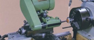
Let's talk about creating a control program for a CNC lathe or milling machine using the example of the most popular software. We would like to note that the quality of the final result depends not only on how good the software is chosen, but also, to a greater extent, on the metalworking equipment itself. We suggest ordering a station with numerical control from the company. There is a wide range of possibilities and many varieties, and you can also order the creation of custom-made devices.
Mach3
We already mentioned it when we talked about two-dimensional modeling. But the software is ideal for designing 3D models. It was created not as CAD, but as specialized software for CNC tasks. This determines how convenient the program is for its intended purposes. To run it on a computer, it must have an operating system from Microsoft, which, by the way, is a rare condition. The PC must be connected to one of the machines:
- milling;
- turning;
- gear cutting;
- engraving.
By the way, you can use not only a desktop computer, but also a laptop, which greatly simplifies the task of the manufacturer. Despite the fact that the interface is English, there are instructions that are written in Russian.
NC Studio
The software is most often used in the woodworking industry. The control is carried out by a wood milling machine. Furniture is often created with its help. We list the main advantages of the system:
- Easy to understand interface.
- Great graphics.
- Virtual software simulation.
- It is perfectly compatible with major CAD systems, so the file can be “uploaded” from a third-party design environment.
- Ideal for beginners to master.
- Built-in protection prevents unauthorized changes to settings.
EMC2
The main advantage of the software is that it is free to use. Accordingly, the functionality is significantly limited. But if there is no need for industrial production, and the CNC machine is used for private or small commercial purposes, then sometimes this software is sufficient. Note that it is installed exclusively on LinuxCNC.
What is CNC G Code
This is a system of commands perceived by computer-controlled machines. It was created at the dawn of the 60s by the EIA (Electronic Industries Alliance) association, but it was finalized to a ready-to-use format (RS274D) only in 1980. Later, at the next meeting of the relevant committee, it was approved as the ISO 6983-1:1982 standard. In the Soviet Union, GOST 20999-83 was introduced to regulate its provisions, and ISO-7 bit began to denote it in the technical literature.
From that time to this day it has been widely used, both independently and as a basic subset for creating similar languages, and is constantly being improved and expanded.
Program capabilities
A numerical control panel can be installed on almost any equipment that performs mechanical processing of material. These are tasks such as turning, milling, drilling, cutting off, threading, grooving and much more. At the same time, you can work with metal, wood, plywood, paper and cardboard, glass or plexiglass, and other synthetic polymers. Usually software is written when:
- mass production, when a similar volume would take a lot of time manually;
- high precision needs;
- a special, individual and very complex knot that is almost impossible to accurately turn by hand.
Thus, the applications of equipment are so wide that there is no point in listing the branches. Almost any industry, from making paper clips to building spaceships, cannot do without such software.
Requirements for writing algorithms
They must be clearly structured and divided into frames, each of which must end with a CR/LF separator. At the end you need to put M02 or M30. Associated comments are left in parentheses, either immediately after the characters or on a separate line. The same functions can be repeated in any chosen sequence and any number of times, if this is a rational decision.
If the algorithm generates CAD, the operator needs to control the result. To do this, he needs to know the dimensions of the part, the thickness of the removal layer, the parameters of the cutter, and the depth of insertion of the blade.
The process of developing programs for CNC machines
Let's list the steps step by step:
- Collection of data about the required unit and its production tasks.
- Creating sequentially first a sketch, then a drawing, a 3D model.
- Receiving a set of commands.
- Code correction and emulation.
- Test launch and production.
At the stage of collecting information, we find out what kind of element it is, where and under what conditions it will be used, its dimensions, the nature of the surface, including roughness, as well as allowances, which are extremely important for turning.
Table of auxiliary (technological) commands G and M code for CNC machines
| Symbol | Description |
| M00 | stop before pressing "start" |
| M01 | similar to the previous one, but subject to confirmation mode |
| M02 | completion of the algorithm |
| Start of spindle rotation | |
| M03 | clockwise |
| M04 | against |
| M05 | stop |
| M06 | change of working body |
| M07 | activation of additional cooling |
| Main cooling | |
| M08 | inclusion |
| M09 | shutdown |
| M30 | end of data output |
| M98 | start of subroutine |
| M99 | its completion, return to the main algorithm |
Now you see how, for example, G49, G94 and G99 CNC codes differ from each other, but there are also functions with other letters. What are they doing? We suggest you look into this issue.
CNC development
Each individual machine has control commands, they are written in the instructions. Using this set, you need to code the entire layout for the desired available options. These may include the following:
- Startup and shutdown.
- Selection of cutting tool.
- Moving a cutter along two or more planes.
- Determination of cutting mode and speed.
- Additional mechanisms, such as chip removal or lubricant supply.
The introduction of this program can be carried out in two ways:
- On a personal computer, using specialized software, encoding occurs automatically, then the ready-made set of commands in the code is transferred to the equipment using a recording device.
- On the machine itself there is a stand from the numerical control panel. There you can enter the necessary commands.
Factors to Consider
It should be remembered that the more complex the device, the more nuances of use. Important things to consider:
- How many tools can be used simultaneously - the number of tasks performed in parallel.
- What operating power is used.
- Feed speed. If you select a parameter higher than recommended, this can lead to overheating of the workpiece and cutting edge, leading to defects and deformations.
Programming Methods
The programming process can be performed:
- Manually. The technologist compiles a program on a remote PC using a text editor. Then it transfers it to the CNC memory via a USB flash drive, optical disk, floppy disk or through interface ports connected to a PC with a cable.
- On the CNC console (stand). Commands are entered from the keyboard and displayed on the screen. The set of icons corresponds to a list of canned cycles that can be assigned, reducing the recording volume. A number of systems (Fanuc system, HEIDENHAIN) support an intuitive interactive interface, where the operator creates a processing program by sequential selection.
- Automated in integrated CAD/CAM/CAE systems. An advanced method that requires the implementation of a unified electronic system at all stages of the production cycle.
The first method can be used for programming simple turning operations, processing groups of holes, milling along two coordinates without processing profile curves. The time spent is high, errors are detected on the machine.
Programming from the remote control allows you to perform all of the above, and with an interactive input language, even more complex transitions of 2.5 and 3-axis processing. The best option for adjusting existing or creating batch processing programs based on a “template”.
Working in CAM systems, for example: MasterCAM, SprutCam, ADEM involves obtaining a sketch, a model from CAD, interactive selection of a machine, movement limits, fixtures, tools (MI), modes, transitions and processing strategies, setting correctors. Based on this, the postprocessor converts the trajectory of the RI into a control program (CP). Virtual testing can be viewed on the monitor, eliminating obvious errors (gouges, uncut allowance, collisions with equipment), optimizing the trajectory.
Selecting a processing strategy and tool
At the second stage of working with the CAM system, the technologist-programmer selects a strategy and processing parameters, assigns a tool and cutting modes. A modern system usually has a solid set of strategies and allows you to process the same part in different ways.
Conventionally, all strategies can be divided into roughing and finishing, flat and volumetric processing strategies. Let's consider strategies typical for most modern CAM systems.
Flat processing
Planar machining strategies are used when working with 2D geometry. In this case, not much variety is required - all processing comes down to milling a contour or plane, making a pocket and processing holes (Fig. 12.14-12.17).
Rice. 12.14. Contour strategy. For rough milling, the number of passes and the step between them (overlap) are indicated.
Rice. 12.15. Pocket processing. This strategy is designed to sample closed regions. The main parameters are: the step between the cutter passes and the type of trajectory (parallel, spiral, zigzag, etc.).
Rice. 12.16. Processing the plane (Face). The main parameters for this strategy are: the pitch between the cutter passes and the cutting angle (45 degrees in this example).
Rice. 12.17. Hole processing - drilling (Drill), threading (Threading), boring (Boring). The main parameters are the type of operation and the depth of processing.
Volumetric processing
Volumetric processing strategies are designed to work with 3D models. These strategies are very diverse, but all of them can be conditionally divided into draft and finishing.
Volume roughing strategies are designed to quickly remove large volumes of material layer by layer and prepare the part for subsequent finishing. Volumetric finishing strategies are used to finish milling surfaces with the required quality. Often, during volumetric finishing milling, the movement of the cutting tool is controlled simultaneously in at least three coordinates. As a rule, spherical cutters are used for volumetric machining. In this case, it is extremely difficult to calculate the tool movement independently, without using a CAD/CAM system.
As examples, let's look at some volumetric processing strategies in more detail.
Pocket treatment is a strategy designed to effectively remove material from closed or open pockets. There are many pocketing patterns: zigzag, one direction, parallel and circular spiral. A modern CAD/CAM system selects the optimal milling pattern, ensuring maximum productivity and a minimum number of idle strokes. Typically, this strategy consists of sequentially removing material layer by layer and performing a final finishing walk around the contour at the final depth. With a zigzag pocket processing pattern, the type of milling changes - from uphill to downhill or vice versa.
The radial machining strategy is typically used for roughing or finishing round shaped parts. In this strategy, the tool moves from the center of the part to its outer boundaries (or vice versa) with a gradual change in the angle in the processing plane.
Rice. 12.18. Layer processing of the pocket.
Rice. 12.19. Rough radial machining.
Using vertical roughing, you can quickly process a part using movements similar to drilling. Productions using this strategy purchase special plunger cutters that allow you to quickly select material and have a coolant supply through the tool axis. The vertical roughing strategy is excellent for deep depressions and pockets.
Rice. 12.20. The result of applying the rough vertical sampling strategy.
The residual milling strategy (refinishing) allows you to automatically remove material remaining from a previous operation. To increase processing productivity, it is customary to select material first with a large-diameter tool, and only then mill in hard-to-reach places with a smaller-diameter tool. The system, analyzing the volume of removed and remaining material, automatically generates a trajectory for sampling material that was not removed in the previous processing operation.
The contouring strategy is used for roughing or finishing contouring of free-form parts. The essence of the strategy is to remove the allowance by passing the cutter along the contours created by “shifting” the boundaries of the current layer along Z.
The flow line machining strategy is used for finishing any surface. The system creates trajectories taking into account the shape and direction of surfaces.
The pencil strategy is for finishing corners and joints between surfaces.
Rice. 12.21. Reprocessing strategy with a smaller tool.
Rice. 12.22. Volumetric contouring.
Rice. 12.23. Processing along stream lines
Rice. 12.24. Pencil processing.
The projection processing strategy allows you to apply a unique pattern of the tool path to any area of the machined surface or project a flat path onto a 3D model.
Rice. 12.25. First, a path was created for processing the flat sketch “Wolf”. And only then the trajectory was projected onto a spherical surface.
After choosing a strategy and determining the main processing parameters, you need to assign a cutting tool, or select it from the tool library. At the same stage, the cutting modes are determined: cutting feed rate, spindle speed, and the switching on or off of the coolant is programmed. The result of the second stage is the formed trajectory. A new technological operation should appear in the tree of operations of the CAM system.
What G-codes look like for CNC: example of a control program for milling
We invite you to see what listing is like when processing workpieces of the simplest forms. Let's say we have a circle and a triangle.
Then in the first case, our set of functions will look like this (we present it line by line, with explanations):
- O001 (Circle) serial number and name (can also be written in transliteration).
- G00 Z0.5 Sets the safe height of the tool.
- G00 X-80 Y0 the organ moves to the processing starting point.
- G01 Z-2 F60 the blade cuts to the proper depth (2 mm).
- G02 I10 F80 Circular metal removal occurs.
- G00 Z0.5 The tool is raised again.
- G00 X0 Y0 return to the starting position.
- M30 end of the program.
In the second case, with a triangle, the listing will look like this:
- O002 (Triangle) number and name - everything is as simple as possible here.
- G00 Z0.5 F70 installation of the working element at a safe height.
- G00 X20 Y30 moves to the starting point of the operation.
- G01 Z-3 F60 cutting the blade to the required depth (3 mm).
- G01 X20 Y150 F60 – passage along the first leg.
- G01 X110 Y30 – processing of the hypotenuse.
- G01 X20 Y30 – passage along the second leg.
- G00 Z0.5 – the cutter returns to a safe height.
- G00 X0 Y0 – return to the initial position.
- M30 – completion of the algorithm.
We looked in detail at G-codes for CNC milling machines, and for the machines themselves, start mastering programming. Well, the equipment, modern and reliable, into the memory of which you can enter any written program, is already ready to be sold by its direct manufacturer - Izhevsk.