Important! Be sure to write down the password on a piece of paper and hide it in a secret place, after which do not forget to save the settings.
The fact is that there are cases when attackers connect to the router. Then they can steal your data to carry out various fraudulent plans.
- When the settings are saved, go to the maintenance section and click “reboot”. After this, you can use the Internet without any problems.
How to connect the Internet to a computer without a router
If you have Internet on your phone, you can easily do it on your computer. Connecting to the Internet on a PC without a router takes 3 minutes. After this, you will be able to use the Internet more conveniently from your computer.
For this we need:
- computer;
Connection procedure
The connection occurs as follows.
- Turn on the Internet connection on your smartphone.
- Connect your phone using a USB cable to your computer. Wait 1-2 minutes for the drivers to install on your computer. After this, a window will appear asking you to connect a new device.
- Go to the following path on your smartphone: “menu” - “settings” - “more” - “modem mode” - “USB modem”. Move the slider to the on position. After this, you will have Internet access on your computer.
We hope this article was helpful to you. And now you know how you can connect to the Internet on a router without using a computer. We wish you success!
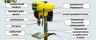
Features, purpose and description of faceplates for a lathe
When working with a lathe, in order not to harm yourself or spoil the workpiece, you need to securely fasten it. Usually the lathe already has its own clamp, however, its capabilities are very limited.
For example, parts with large flaws, or simply very large ones, cannot fit into the cartridge. For such parts, a faceplate is installed on the machine.
DIY screwdriver chuck repair
This is a moving element of the tool, which consists of many rubbing parts. During operation, it is subject to wear resulting from the action of friction forces, impact forces and other factors. The chuck's runout and excessive play can frighten an inexperienced craftsman. In some cases, it is not always possible to allocate the time or finances to contact a repair shop. Therefore, we will look at how you can do it yourself when repairing various tool malfunctions.
Repairing a screwdriver with your own hands when the chuck is loose
A small play within 1 mm usually does not create visible problems during operation. If the value is larger, you should pay attention to the condition of the gearbox. So, the procedure is as follows:
- Unscrew the bolts securing the top cover of the tool. Let's take it off.
- Unscrew the electric motor from the gearbox. We inspect the fastenings.
- Let's disassemble the gearbox. Often the cause of failure is a malfunction of the bushing located inside. It is possible to remove the bushing using the steps described at the beginning of the article (see how to remove the cartridge manually). The bushing is easily pressed out by hand.
- We are replacing the bushing. Then we assemble everything in the following sequence: bushing, shaft, bushing bearings, retaining ring. Lubricate the rubbing parts.
- After this, we assemble the gearbox in reverse order. We attach it to the electric motor.
- Assembling the screwdriver body.
Repairing a screwdriver with your own hands when the chuck runs out
The main culprit for this problem is the screwdriver gearbox. To make sure of this, you need to remove it by dismantling it in the above manner. This particular breakdown may indicate several problems in the gearbox, which we will indicate below. The reason may be:
- violation of the gearbox shaft geometry;
- production of gears;
- malfunction of the shaft support bearing;
- wear of the pins securing the satellites of the planetary gear.
The above parts are produced only in factories, so you won’t be able to make them yourself. All you have to do is purchase them and replace the broken ones.
Varieties
Due to the widespread use of faceplates, it has a large number of modifications, mounting options, etc., therefore, a large number of types.
Universal and special
Typically, such faceplates are a mixture of several of the above types. Such faceplates are created for working with more complex parts, but even they are not always suitable for them, which is why it is modified to the required parameters.
Part with squares
When processing products with low rigidity, modifications with squares are used. The workpiece in such devices is mounted on a separate flat or prismatic base.
The base is made in the form of an angle, its second edge is attached to the surface of the washer. To ensure the integrity of the workpiece, fastening is provided at several points over a large area.
Leashes
Such faceplates have two T-shaped holes, in one of which there is a leash, and in the other there are clamps. The part is attached to the surface with screws in the center. In addition, T-shaped grooves are responsible for fastening.
With holes
This faceplate has a special design in the center for threaded connection to the spindle. The part has 3 holes for clamps.
Sometimes washers are attached to homemade bushings by welding. This is done for a more durable fixation; however, models with an already modified design are sold.
T-slots
On the surface of such equipment, T-shaped grooves are made, similar to those used on tables of milling machines. Special stops or fastening nuts are inserted into the grooves. During processing, the product is pressed to the plane with screws.
The design of the device makes it possible to fasten almost any product. The grooves on the surface of the disk are usually located orthogonally. Depending on the purpose, the number and frequency of grooves change.
With through grooves
Basically, these faceplates are needed for fastening irregularly shaped parts. There are several holes on it, some of them are through, and some are not.
This type does not have a certain number of recesses. Some of them are in grooves. The disk also has stiffening ribs that are mounted.
Installation and use rules
On screw-cutting lathes, faceplates are installed on the headstock spindle. And in rotary lathes, the faceplates are part of large rotary tables.
On universal lathes
Jaw chucks are considered universal, as they have a large number of varieties and jaws, but despite this, not all parts can be simply fixed in the chuck. Such parts can be levers, connecting rods, etc., which are not symmetrical. It is for such parts that faceplates are used.
Parts are usually fixed using bolts or cams. Uneven parts are secured with a clamp in the center. If the part needs to be attached relative to the axis, low shims may be needed to raise the bar. The pads must be equal to the walls of the part. To prevent the part from falling out, the strips must be at the level of the faceplate.
Usually a counterweight is included with the faceplate. If it is not installed, the machine will vibrate, causing the part to last less. If the balancing does not change position after stopping, then all calculations were made correctly.
For rotary lathes
Unlike the faceplates of a universal machine, on them they are an additional fastener, while, like on a rotary lathe, they are the main fastener. On rotary lathes, the faceplates are a rotating table.
It looks like a large disk and has a central mount and a sleeve for attaching parts. The bushings of such faceplates quickly fail, but they can be easily replaced without harm to the faceplate itself. Several T-shaped slots extend from the center, in which there are parts for fastening.
In addition to the disk, the faceplate has a very complex structure at the bottom. In the center of the structure there is a hole for the spindle. Bolts are used to secure parts. The design also has: stiffening ribs, guides, and sometimes it is modified by adding a few more guides.
Self-centering
One type of fastening for a rotary lathe is a self-centering faceplate. Typically, it is used for better fastening.
This type of faceplate has a round shape with a hole in the middle. The hole has the same diameter as the main bushing. It has several T-shaped holes that help secure the part at a certain distance from the hole.
Screwdriver chuck: description, function
The cartridge is a metal cylinder with a cavity inside, equipped with a ring and a control sleeve. It is fixed to the shaft. With its help, the drill or grinding attachment is securely fixed in it for further work. The fixation of the working part of the tool (drill) is ensured by the thread. The drill is tightened in two ways. The first method is to tighten it with a special wrench; in the second method, the drill is tightened when the chuck is rotated in the direction opposite to the axis of rotation of the drill.
How to disassemble a screwdriver chuck
Despite the fact that today there are many models of screwdrivers on the market, they have the same general approach to removing such an element as a cartridge. Now we will briefly describe it.
In order to unscrew it, you need to remove the screw securing it to the shaft. It is located inside the cartridge; the screw should be rotated clockwise. After you have unscrewed the screw, you should jerk the cartridge in the opposite direction.
Attention! If you try to unscrew it manually, you must set the drill to second speed if it is two-speed. When purchasing a tool, it is advisable to lubricate the screw with machine oil. In some cases, when this element does not want to give in, then you should put the tool on first speed, hold it in your palm, and turn the reverse to the left. The cartridge should come off the thread easily.
How to replace a screwdriver chuck
It will not be easy for an untrained user to replace it, since without the help of a special tool you will not be able to do it with your bare hands. There are two ways in which it can be removed, and we will consider them further in our article. In order to change it, you should pay attention to the actions that we described in the article above. Dismantling is performed with the following tools:
- A hex key is usually a 10mm L-shaped metal rod. Its short part should be fixed in the chuck, the long part should be rested against something, for example, a table. We turn the cartridge, and then remove it by turning the key.
We looked at the dismantling method using a key.
The method to remove the element manually is described above. Important! In especially severe cases of jamming of moving elements, you will have to completely disassemble the tool body and remove the spindle with gearbox and chuck. To do this, you will need a vice in which you will clamp the tool, and a pipe wrench with which you will unscrew the chuck. Tools designed for inserting a wrench make this task easier. But they are not found on all models, so you will have to deal with it using the above method.
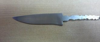
Is it possible to make the part yourself?
Of course, making a full-fledged faceplate yourself will be extremely difficult, and even in some cases, too expensive, but there are options that you can make yourself without much expense. They won't fit all the pieces, but they can secure the basic pieces.
Preparation of the faceplate
Apply the parameters you need to the beam. Using a compass, mark a diameter slightly larger than the central hole. This is necessary so that when gluing you do not “eat” a few extra millimeters and make the part smaller than necessary.
Coat the parts you are going to glue with hot glue, stepping back a centimeter from the edge. Hold the parts properly so that they finally stick together.
To make it you will need:
- Tools: Lathe, cutters, plumbing kit, earplugs/earphones for shooting, shield, inverter and all its accessories, electrodes (2.5 mm), hot melt glue, machine.
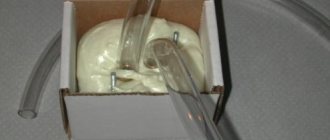
- Details: Nuts, washers, dry birch firewood. Cut the extended nut in half with the machine running.
Next, take the body washer. Make sure the nut doesn't fall through. Place the nut with its ribs in the center of the washer. Weld half of the nut to the washer, welding first one side and then the other.
Using faceplates on universal lathes
In conventional jaw chucks, workpieces of various shapes can be placed, symmetrical about the axis. Various numbers of jaws and multiple design options ensure the versatility of the chucks. However, there are parts whose placement in cartridges is inconvenient. These include parts that are asymmetrical about the axis: levers, housings, connecting rods, etc. Special devices are used for them, including faceplates.
rear view (cam lock attached to spindle)
The faceplate for universal lathes has the form of a steel or cast iron disk with a flange for fixing to the spindle. On the front side there is a base surface for fastening the workpiece or equipment; the grooves are used for preliminary alignment of the workpiece. There are also several radial grooves for fixing the workpiece during processing. Stiffening ribs may be located at the rear. The base surface of the faceplate fits onto the conical or cylindrical seat of the spindle; fixation is carried out depending on the type of spindle end. When using a faceplate, the manufacturer discusses the maximum permissible speed of rotation of the faceplate.
The following types of faceplates are distinguished:
- smooth,
- with threaded holes,
- with radial grooves,
- with circular grooves.
- leashes.
Installation of parts on the faceplate of universal lathes
The parts are fastened to the faceplate using strips and bolts. The bolts used can be pressed or screwed into cams to move and secure into the grooves.
Axisymmetric parts are secured with clamps or a central clamp. Fastening asymmetrical parts relative to the axis is much more difficult. To do this, use low pads or higher thrust posts, which allow you to raise the slats above the faceplate. The height of the racks should be the same as the height of the walls of the part. The clamping bolts that hold the strips in place are located as close to the part as possible. The slats must be parallel to the faceplate, otherwise the part may jump out during rotation. The correct installation of the workpiece on the faceplate is checked with a thickness planer. Checking the location of the first workpiece from a batch is carried out in the same way as in a four-jaw chuck.
Parts processed on a faceplate often have a center of gravity offset relative to the central axis of the machine. Therefore, a counterweight of the required mass calculated for a specific part is placed on the faceplate, which returns the center of gravity to the central axis. Without a counterweight, the spindle will run out and vibrations will occur on the machine, reducing the life of the cutting tool and spindle head bearings.
Rice. Fastening the part to the faceplate using a counterweight: 1 – faceplate; 2 – square; 3 – workpiece; 4 – counterweight
Balancing is done by manually turning the faceplate. If it does not change its position after stopping, then the weight and position of the counterweight are chosen correctly.
You can consider the fastening of a part using the example of a connecting rod - an elongated part, which consists of two bushings of different diameters connected by a jumper. The part is installed in the faceplate to machine the inner surface of a larger hole. For fastening, two strips with pads and a square are used. The planks are clamped with bolts inserted into the holes of the faceplate. Centering is carried out using squares installed in T-slots. A counterweight is placed on the faceplate on the opposite side of the connecting rod.
Thus, the faceplate allows you to place an irregularly shaped workpiece on the spindle and eliminate eccentricity. However, installing and centering the part requires more time than jaw chucks.
Faceplate of rotary lathes
The faceplates used on screw-cutting lathes and rotary lathes are significantly different. If on screw-cutting lathes faceplates are used as an auxiliary fastening for complex workpieces, then on rotary turning machines the faceplate is the main method of fastening and acts as a necessary element of the machine. On rotary lathes, the faceplate functions as a horizontal rotating table.
The faceplate of rotary lathes is a large part in the form of a disk with a central mounting hole. A sleeve can be pressed into the hole into which devices are installed. The presence of the bushing is due to increased wear in this area. The worn bushing is replaced, and the faceplate is used further. On top of the faceplate there are T-shaped slots diverging from the center. They are equipped with clamping jaws and other devices for securing the workpiece.
From below, the faceplate has a complex structure. In the center there is a protrusion in the form of a sleeve into the hole of which the spindle is inserted. To secure the connection, screws pass through the spindle flange. At a distance from the center, there are stiffening ribs. The edges of the faceplate rest on circular guides. Heavy faceplates have additional guides.
The faceplate drive has two structure options. The rotation of the faceplate is transmitted through a large gear mounted at the bottom. Helical gearing is considered more reliable and suitable for high loads.
Self-centering faceplates
Vertical lathes use various devices for securing workpieces. One of them is a self-centering faceplate. It is designed to align and improve the reliability of workpiece fastening.
A self-centering faceplate looks like a disk with a central hole. The diameter of the hole coincides with the diameter of the hole in the bushing of the base faceplate, which performs the functions of the work table. Thus, a self-centering faceplate is placed above the faceplate of the machine.
The surface of the self-centering faceplate also has T-shaped grooves. The grooves allow you to secure the workpiece at the same distance from the center. It is also possible to install additional accessories on this faceplate.
Accuracy standards for tabletop screw-cutting lathes:
| Machine data: | |
| Height of centers [mm] | 90 |
| Chuck diameter [mm] | 100 |
| Maximum processing diameter [mm] | 180 |
| Distance between centers [mm] | 300 |
| Bed width [mm] | 100 |
| 1 speed. Spindle speed [rpm] | 150 – 1500 |
| 2 speed. Spindle speed [rpm] | 300 – 2500 |
| Spindle inner taper | MK 3 |
| Through hole diameter of three jaw lathe chuck [mm] | 21 |
| Movement of the upper caliper slide [mm] | 75 |
| Travel of the cross slide of the caliper [mm] | 85 |
| Tailstock quill inner cone [mm] | MK 2 |
| Tailstock quill travel [mm] | 60 |
| Automatic longitudinal feed [mm/rev] | 0,1-0,2 |
| Range of cut metric threads [mm/rev] | 0,5 – 3 |
| Range of cut inch threads [threads/inch] | 8 – 44 |
| Difference between the heights of the tool holder supporting surface and the center line [mm] | 10 |
| Maximum cross-section of cutter holder [mm] | 10 |
| Dimensions: | |
| Overall dimensions, mm] | 830 x 395 x 355 |
| Total net weight of the machine, [kg] | 65 kg |
| Total gross weight of the machine, [kg] | 80 kg |
| Lubricants: | |
| Acid-resin-free motor oil (Mobil-oil, Fina and others) | |
| We recommend gun oil. | |
| Measured quantity | Measuring circuit | Limit value |
| Spindle radial and axial runout | A: 0.009 mm B: 0.01 mm | |
| Radial runout of the spindle connecting surface | 0.009 mm | |
| Radial runout of the mandrel installed in the inner cone of the spindle | A: 0.015 mm B: 0.03 mm | |
| Tailstock quill parallelism | A: 0.025 / 50 mm B: 0.015 / 50 mm | |
| Runout of the mandrel installed in the centers of the spindle and tailstock | A: 0.03 mm B: 0.03 mm | |
| Spindle parallelism | A: 0.03 / 250 mm B: 0.03 / 250 mm | |
| Parallel movement of the upper carriage of the spindle axis support | 0.04 / 75 mm | |
| Radial runout of lathe chuck | 0.04 mm | |
| Radial runout of the measuring mandrel. fixed in the lathe chuck: |
Comments • 0
Thanks for the answer, we’ll look at the topic on the chipmaker, about the bearings. I loosened the faceplate, of course. I also removed the cartridge (I have it on hexagons. I shortened the hexagon so that it could fit between the cartridge and the PB and moved the screws, then unscrewed it with my hands as best I could cartridge. And the faceplate, it doesn’t lend itself. I asked you in another topic, but I’ll ask again. Do you have a tool holder for 16th cutting tools? Just according to the passport, this machine has 12th ones. I looked at a bunch of photos from the Internet. The tool holder is the same as yours. I think not machined, visually it would be clear that the thickness was reduced by 4mm. But the incisors normally stand at 16th in the centers!). I don’t understand what the catch is.
@Vladimir Kirichenko Thank you for the answer and the exact dimensions of the tool holder! I’m also interested, I’ll be in the workshop - I’ll definitely measure everything and write back to you.
Regarding the tool holder: 1. On mine, along the axis of the centers, the incisors stand 12 mm high from the base of the incisor. 2. The thickness of the lower shelf of the tool holder is 10mm 3. The distance between the shelves is 18mm. It would be interesting to see that your 16mm ones are in the center.
Reasons for drill misalignment
The reason for misalignment of an electric drill in most cases is that the chuck itself is too tight at the factory. It turns out that the cartridge warps along its axis, and one of its parts is pressed against the body more strongly than the other. The resulting misalignment is what causes the drill chuck to play. If you re-tighten it again during reassembly, the effect may return.
Thus, at home you can center any drill or screwdriver in 15 minutes. It is not at all necessary to return the product to the store or take it to a service center for repairing power tools.
Chipguru
- Forum Forum Rules
- Rules for Editors
- Competition rules
- Flea Marketer's Guide
- Educational program on the forum Change the color of the forum
- How to insert photos
- How to insert links
- How to embed a video
- How to indicate offtopic
- How to quote
- Stitching messages
- Theme icons
- Subscribe to topics
- Auto-subscribe to topics
- Metal
- Bearings
- Steel grades and alloys
- Thread diameters
- Unanswered topics
- Active topics
- Search
- our team
Method for setting the headstock of a lathe
Method for setting the headstock of a lathe
Message #1 e_Vyacheslav » December 31, 2022, 21:04
Method for setting the headstock of a lathe
Post #2 DOC » 31 Dec 2022, 21:17
TOS MN-80s 1952
Message #3 e_Vyacheslav » December 31, 2022, 21:40
If only the flange is crooked, then it will not affect the control groove
Sent after 4 minutes 38 seconds:
TOS MN-80s 1952
Post #4 ROW » 31 Dec 2022, 21:57
TOS MN-80s 1952
Post #5 DOC » Dec 31, 2022, 10:00 pm