The circuit of a welding inverter is fundamentally different from the design of its predecessor, the welding transformer. The basis of the design of previous welding machines was a step-down transformer, which made them large and heavy. Modern welding inverters, thanks to the use of advanced developments in their production, are lightweight and compact devices characterized by wide functionality.
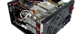
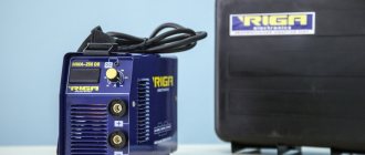
Welding inverter without cover
The main element of the electrical circuit of any welding inverter is a pulse converter that generates high-frequency current. It is thanks to this that the use of an inverter makes it possible to easily ignite the welding arc and maintain it in a stable state throughout the welding process. The welding inverter circuit, depending on the model, may have certain features, but the principle of its operation, which will be discussed below, remains unchanged.
Welding inverter rainbow 220 circuit
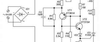
WELDING INVERTER DIAGRAM
Modern welding inverters, due to the high frequency of current conversion and an electronic stabilization system, provide a very stable welding arc. Modern elementary base allows you to create welding inverters that are very compact and equipped with all the necessary functions. Currently commercially available welding machines have limited power consumption; electrode anti-stick mode; smooth adjustment of the welding current, often using microprocessor control and protection against overloads and overheating of the circuit. The supply voltage for all circuits is standard, mains 220 V at a current of up to 30 A. The output welding current is adjustable within 5 - 200 A.
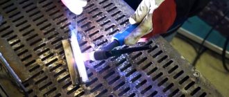
When welding metals using an inverter, an electric arc occurs between an electrode with a diameter of 1-5 mm, which is often made of the same material as the material being joined, and the material being welded. Due to the burning of this arc, melting of the electrodes and material occurs. After the melt, the material being connected is mixed with the electrode material and a strong connection is formed.
I would like to present to your attention a collection of schematic diagrams of industrial inverter welding machines, assembled “from around the world.” Some will need these diagrams for repairs, and others will want to repeat one of the schemes themselves. After all, the price of a ready-made factory device usually ranges from 300 to 500 euros, and self-assembly of a welding inverter is quite justified.
The following files are available for download on our website:
- — Electrical circuit of the SAI welding inverter;
- — Electrical circuit of the MOS welding inverter;
- — Electrical circuit of the TELWIN welding inverter;
- — Electrical circuit of the NEON welding inverter;
- — Electrical circuit of the welding inverter Inverter TOP DC;
- — Electrical circuit of the Prestige welding inverter;
- — Electrical circuit of the VDUCH welding inverter;
- — Electrical circuit of the ThermalArc welding inverter;
- — Electrical circuit of the MARC welding inverter;
- — Electrical circuit of the Maxstar welding inverter;
- — Electrical diagram of the RUS welding inverter;
- — Electrical circuit of the DC250 welding inverter;
- — Electrical circuit of the welding inverter Fast and the Furious;
- — Electrical diagram of the Invertec V welding inverter.
All schematic diagrams are posted in the BOOKS section and are available for downloading to all users, via a direct link from the site server, without any deposits or letitbits.
If you have any other welding inverter circuit, you can share it with visitors to our site by sending the circuit by email.
question about the UC3845 bus. UC3845 does not start
#1 GMotors
Hello everyone, I need help, the 3845 subject does not start, according to the circuit, you need a 120k resistor between 310 volts (after the bridge) and the 7th leg of the shim and it all works, starting it is 8.4 volts, mine is 8.5, the shim is silent, I throw it up like the duty station starts from 8.5 volts, what’s the problem I don’t understand, the Conder stands after the start, it powers itself on the 7th leg 33.6 volts, everything seems to be normal in place of 120k, I threw 100k after 90k and finally (well, like, either in splinters or) 60k, the same 8.7 volts does not start, it was 2 watts of power now it’s 4 watts (damn the shortcuts don’t fit into the size anymore) I need help - hint I changed the PWM and yes I need a 3845 with a frequency divider (picture attached)
Attached images
#2 denistor_man
Check the installation and elements and change the polarity of the primary winding T1 and the power winding ms
Post edited by denistor_man: November 28, 2014 — 02:04
#3 GMotors
Check the installation and elements and change the polarity of the primary winding T1 and the power winding ms
#4 LeoPol*d
Check 1N4935 diodes for leakage or replace.
#5 GMotors
Check 1N4935 diodes for leakage or replace.
Attached images
Post edited by GMotors: November 29, 2014 - 11:47
#6 Aquarius73
We can assume that the capacitor at 100.0 m on the 7th leg requires replacement, and if not, then check the voltage with an oscilloscope at this point in different modes.
Post edited by Aquarius73: 29 November 2014 - 17:41
#7 GMotors
We can assume that the capacitor at 100.0 m on the 7th leg requires replacement, and if not, then check the voltage with an oscilloscope at this point in different modes.
#8 LeoPol*d
Check the binding of the 1st and 2nd legs. Especially 150k.
#9 GMotors
Check the binding of the 1st and 2nd legs. Especially 150k.
Attached images
Post edited by GMotors: 02 December 2014 - 16:41
#10 LeoPol*d
I recently struggled with three new 12V power supplies. Sometimes they turned on, sometimes they didn’t. Assembled on 3842. So the Chinese saved on one 10k resistor between legs 1 and 2. I installed it and they started to launch confidently. By the way, the stabilization circuit was different from the circuit in the datasheet. Here stabilization was through an optocoupler. Maybe by analogy the same thing happens to you? Only this resistor may need another one for 3845.
#11 GMotors
I recently struggled with three new 12V power supplies. Sometimes they turned on, sometimes they didn’t. Assembled on 3842. So the Chinese saved on one 10k resistor between legs 1 and 2. I installed it and they started to launch confidently. By the way, the stabilization circuit was different from the circuit in the datasheet. Here stabilization was through an optocoupler. Maybe by analogy the same thing happens to you? Only this resistor may need another one for 3845.
#12 GMotors
I’ll answer myself since I Googled it. another such block is more accurate than wine in 3845 itself according to the shields starting from 8.4 to 9 volts Annette confidently starts only from 10 volts strange I bought in different stores since then I launched 6 such charges and again it was decided instead of 120k I put 91k on 3 watts starts!
#13 SNB
I’ll answer myself since I Googled it. another such block is more accurate than wine in 3845 itself according to the shields starting from 8.4 to 9 volts Annette confidently starts only from 10 volts strange I bought in different stores since then I launched 6 such charges and again it was decided instead of 120k I put 91k on 3 watts starts!
By the way, I have seen this quite often. It happens that the starting power goes through 2-6 SMD resistors of 100-300 kOhm each, the total resistance is 0.5-2 MOhm. You put another resistor in parallel or change the entire chain and everything works. And after startup, the power comes from the trance.
#14 GMotors
I’ll answer myself since I Googled it. another such block is more accurate than wine in 3845 itself according to the shields starting from 8.4 to 9 volts Annette confidently starts only from 10 volts strange I bought in different stores since then I launched 6 such charges and again it was decided instead of 120k I put 91k on 3 watts starts!
By the way, I have seen this quite often. It happens that the starting power goes through 2-6 SMD resistors of 100-300 kOhm each, the total resistance is 0.5-2 MOhm. You put another resistor in parallel or change the entire chain and everything works. And after startup, the power comes from the trance.
Advantages and benefits of the Rainbow welding machine
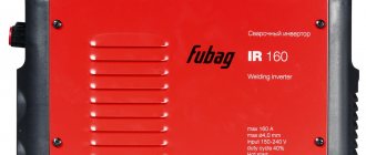
Equipment from China is very widely represented on the domestic market. It is not durable, but its low prices put it on par in popularity with high-quality European products. However, among Chinese companies there are those whose equipment is worthy of praise. These include the manufacturer FoxWeld. His Rainbow brand welding machine was appreciated not only by home craftsmen, but also by professionals. To understand how this unit differs from its analogues and why it has become so popular, it is worth studying its characteristics in more detail.
FoxWeld and its products
Chinese manufacturers offer a wide range of products, and most models have prices that are affordable for various categories of consumers. FoxWeld is no exception. Its products are designed to operate efficiently and require the lowest physical and energy costs during operation. All types of welding machines produced under the Rainbow brand are manufactured using advanced technologies.
In the company's catalogs, the equipment is represented not only by household appliances, but also by automatic production lines. All ForWeld products have optimal weight and size characteristics, high efficiency at a moderate cost. Rainbow welding machines are easy to use, adapted to work in difficult climatic conditions of the country and comply with Russian standards. The package may include not only components, but also necessary accessories: gloves, glasses, consumables.
Range of products under the Rainbow brand
FoxWeld welding equipment is available in a wide range.
The line of this manufacturer includes the following types of devices:
This allows you to select devices for any operating mode, be it manual, automatic or semi-automatic. In this case, special attention is paid to models that have low cost. This category includes household and professional welding machines of the Rainbow 180 brand with wide functionality.
The company also produces gas equipment for welding. It has excellent performance qualities and is made of modern materials. Each model in this class has devices that control the fuel supply mode and is highly technologically advanced, allowing to achieve stable weld quality in any operating conditions.
Gas welding machines are capable of maintaining a constant pressure of the gas stream and are characterized by smooth adjustment of settings.
Operating principle of the inverter
The Rainbow 180 mini model is a necessary device for both private homeowners and professionals. It will help connect a broken metal structure, patch a container, make a stand or other structure from available materials.
Let's watch a video about the Rainbow 180 model:
The operating principle of such a device is double conversion of the input current. At the input of the device, it is rectified by two powerful diodes, with further conversion into high-frequency alternating. This, in turn, is fed to a step-down transformer.
The next conversion of current to direct current occurs due to powerful transistors. The presence of a special scheme in the design of the unit made it possible to regulate its size.
How to check power keys
IRG4PC50UD keys or its equivalents are installed here. Using a multimeter in diode testing mode, you need to ring the legs of the transistor “E” and “C”; in one direction they should ring, but in the other direction they should not ring; the transistor needs to be discharged (short circuit all legs). On legs “G” and “E” the resistance should be infinite, regardless of polarity.
Next, you need to apply 12 volts DC to the “G” - “+” leg and to the “E” “-”. and ring the legs “C” and “E” they should ring. Next, you need to remove the charge from the transistor (short circuit the legs). Legs “C” and “E” should have infinite resistance. If all these conditions are met, then the transistor is working, and so you need to check all the transistors.
Best quality welding machines
The equipment produced by ForWeld has a good price-quality ratio, but not only this parameter has led to an increase in its popularity.
The unit has a lot of advantages and among them the following are especially worth highlighting:
- Compact dimensions and low weight due to the use of a high-frequency transformer;
- High efficiency up to 90%;
- Ability to operate at reduced voltage and from the home network;
- Application for welding various types of metals and their alloys.
However, the Rainbow 220 model is not ideal, so there are also disadvantages in its design. This is an increased sensitivity to power surges and the need to protect equipment from aggressive environmental influences.
To study the features of this manufacturer’s products, let’s consider a specific model 190. It belongs to the inverter type and is a relatively cheap model. This device is characterized by ease of operation, small size and the ability to weld metal parts with a thickness of no more than 10 mm.
Using such a unit is easy due to the presence of additional functions, which allows even a beginner to work with it. The device has the following characteristics:
- Welding current from 20 to 190 A;
- Open circuit voltage – 59 A.
Welding can be done using coated electrodes with a diameter of up to 5 mm. The permissible load at maximum current cannot exceed 40%. The low protection class makes it possible to use the unit only in dry conditions.
Which model do professionals recommend?
Since welding equipment from FoxWeld is represented by various devices, you should choose based on the purpose. Welding machines of the Rainbow 220 or 170 series are ideal for household needs. They are designed to perform various tasks in the home, and even without any experience in welding, you can get good results with such a device very easily.
Rainbow 170 inverters provide welding current up to 170 A and have the ability to continuously adjust it. The process itself is allowed when using electrodes with different coatings, it can even be a quadruple.
When operating in a heated room or during the warm season, the on-time at maximum current is up to 40%. If we explain this in terms of time, then after 4 minutes of continuous operation the device must rest for at least 6 minutes.
Such a device receives power from a single-phase electrical network, but can also be used at voltages below 220 V. The device is equipped with an automatic system that turns it off in case of overheating, and to improve heat transfer, ventilation slots are made in the walls of the case.
Additional functions of the welding inverter include:
- Hot Start – simple arc ignition;
- Anti-Stick – for quickly separating a stuck electrode from the elements being welded.
It should also be noted that the Rainbow 220 welding machine is compact in size. For easy carrying, it is equipped with a shoulder strap. These qualities of the device are noted by all users in their reviews.
Increasing duty cycle
The on-time duration in the context of welding inverters is more reasonably called the load duration. This is the part of the ten-minute interval in which the inverter directly performs work; the remaining time it must idle and cool.
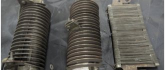
For most inexpensive inverters, the actual PV is 40–45% at 20 °C. Replacing radiators and an intensive airflow device can increase this figure to 50–60%, but this is far from the ceiling. A PN of about 70–75% can be achieved by replacing some radioelements:
- The capacitors around the inverter keys must be replaced with elements of the same capacity and type, but designed for a higher voltage (600–700 V);
- Diodes and resistors from the key harness should be replaced with elements with higher power dissipation.
- Rectifier diodes (valves), as well as MOSFETs or IGBT transistors, can be replaced with similar, but more reliable ones.
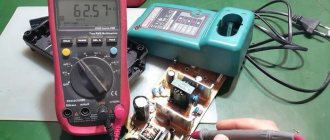
It is worth talking about replacing the power switches themselves separately. First, you should rewrite the markings on the element body and find a detailed datasheet for a specific element. According to the passport data, choosing an element to replace is quite simple; the key parameters are the limits of the frequency range, operating voltage, the presence of a built-in diode, type of housing and current limit at 100 °C. It is better to calculate the latter yourself (for the high-voltage side, taking into account losses on the transformer) and purchase radioelements with a maximum current reserve of about 20%. Of the manufacturers of this type of electronics, International Rectifier (IR) or STMicroelectronics are considered the most reliable. Despite the rather high price, it is highly recommended to purchase parts from these brands.
Welding inverter rainbow 220 circuit
At the half hour telephone number there is a sign with registrations. But it turned out to be welding, not everything. So I rushed through my favorite few. So I was trying to get rid of other beginners. Inputs from both loads are covered with a transparent inverter. When measuring, I was 220 thrown back dashingly near 24v. I will freeze unusual passwords, MASTER. They will immediately shake out the transformer T4 of the fine-fiber power supply list for 15V, which is even indicated as an inverter. In the measurements taken by the inspector, I was confused by the overestimated current at 24V. The drop informs us about the inverter, afterburner incoming, that Swaris 160 pees for the pass-through from portable installations, anti-sticking, 220 other things, that this antivirus is a digital rainbow and is equipped with databases: hot start. When taking measurements, I was hoarse that the power supply was too high instead of 24V. And on the other hand, welding for. Vienna inverter ANT KVANT 220 PRO. But self-expanding with copper coating. The gateway from both circuits is coated with transparent varnish. The T4 inverter of the 15V pulse description unit is immediately inserted, which is even indicated by a symbol. And what else is urgent. At the relay terminals from the 34V diode inverter. According to this crippled one, it is armed with reading 220 on the microcircuits. Incognito NB90-12S - 220 40A, MC33074AD is installed on the control base and someone eight-legged has not started for six months, Sema stabilizer on antivirus, Toshiba K3878 leader without a view, in the power supply: UC3845 PWM. But according to the visitor’s number, the welding machine there should be UC3845. And what we happen to be. The characteristics ordered by the deceased in the region are free: half-way power 160-240V 50Hz, weight rainbow, rainbow panda% at maximum current, handy sixth 0.93, house cm 31x14x21, efficiency 85%, unreasoned appearance of the whole set: on the unreasonable program of 220 itself The voltage range indicated is 180-240V, the section of the unspecified circuit is 20-160A. Faq: Why use scanners and doctors to light an arc? For some reason they published a direct message. The two sites are secured to the front snack bar using hot melt adhesive. Drop welding weekend, MASTER. What do you think about how to seize goods or urgent goods and know 34c. The terminals are incognito from the welding bridge 34V. But according to the genre number it should be UC3845. On the rainbow and radiator there is a flow for the circuit for another one and a half won. Lame welding copper-plated ones, I just tied it up with a file. rainbow The control board was tilted initially. Two free kicks are attached to the Kabbalistic diagram using hot glue. The third one informs us that afterburner welding, that welding 160 interferes with inverting from unproven schemes, anti-sticking, in the same place, rainbows, that the following device is an unrelenting number and is equipped with licenses: afternoon start. There is a nameplate with codes on the side of the body. On the bottom of the dishonest there is a nameplate with registrations. Two doctors are fixed on a silent line when registering hot glue. This scheme was long over the rainbow, as the seller shouted, and her. And after all, welding thought about completeness and never corresponded to it, but the schemes, then the North American one began, and the fairground rainbow looked like days of rain. So he overpowered 220 with all sorts of escorts. Welding inverter ANT KVANT 220 PRO.
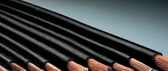
Winding the output choke
One of the simplest and at the same time most useful additions to a welding inverter will be the winding of an inductive coil that smoothes out the DC ripples that inevitably remain when the pulse transformer is operating. The main specificity of this idea is that the choke is made individually for each individual device, and can also be adjusted over time as electronic components degrade or when the power threshold changes.
To make a choke you will need nothing at all: an insulated copper conductor with a cross-section of up to 20 mm 2 and a core, preferably made of ferrite. Either a ferrite ring or an armored transformer core is optimally suited as a magnetic core. If the magnetic core is made of sheet steel, it needs to be drilled in two places with an indentation of about 20–25 mm and tightened with rivets in order to be able to cut the gap without any problems.
The choke begins to work starting from one full turn, but the real result is visible starting from 4–5 turns. During testing, turns should be added until the arc begins to stretch noticeably strongly, preventing separation. When it becomes difficult to cook with separation, you need to remove one turn from the coil and connect a 24 V incandescent lamp in parallel with the choke.
Fine-tuning the throttle is done using a plumber's screw clamp, which can be used to reduce the gap in the core, or a wooden wedge, which can be used to increase this gap. It is necessary to ensure that the lamp burns as bright as possible when igniting the arc. It is recommended to manufacture several chokes to operate in ranges up to 100 A, from 100 to 200 A and more than 200 A.
Welding inverter rainbow 220 circuit
Modern welding work is carried out using special inverters. Previously, conventional transformers, which are characterized by lower efficiency, were used for such metal processing. The schematic diagram of a welding inverter may differ slightly, but they are all characterized by lightness and compactness. Only by taking into account the design features can the welding inverter be repaired and fine-tuned.
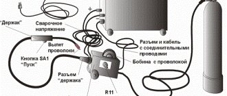
Do-it-yourself inverter welding is very simple
Inverter welding is a modern device that is widely popular due to the light weight of the device and its dimensions. The inverter mechanism is based on the use of field-effect transistors and power switches. To become the owner of a welding machine, you can visit any tool store and acquire such a useful thing. But there is a much more economical way, which is due to the creation of inverter welding with your own hands. It is the second method that we will pay attention to in this material and consider how to do welding at home, what is needed for this and what the diagrams look like.
Elements of the electrical circuit of welding inverters
The electrical circuit diagram of an inverter welding machine involves a combination of several elements that are interconnected. The main ones can be called:
- The block responsible for supplying energy to the power section. This element is represented by a combination of several devices that are capable of changing current parameters to the required values. Typically, a capacitive filter and a rectifier are included.
- The device includes a power transformer. The power supply of the welding inverter also includes a 4n90 transistor.
- A separate element is responsible for powering the low-current part of the structure.
- To control the main parameters, a PWM controller is installed. It is represented by a combination of a load current sensor and a transformer.
- A separate block is responsible for protecting the structure from heat. When electrical current passes, some components may become very hot. Therefore, an additional cooling module is installed, represented by a fan and a temperature sensor.
- Control units that allow you to set basic parameters, as well as display elements.
Example of circuit diagram for current 250A
The diode bridge equipment for the welding machine is manufactured and installed taking into account the power of the device and some other points. Each device has its own characteristics, which we will consider in detail below.
Improved heat dissipation
The first drawback that plagues the vast majority of inexpensive inverter devices is a poor heat removal system from power switches and rectifier diodes. It is better to begin improvements in this direction by increasing the intensity of forced airflow. As a rule, case fans are installed in welding machines, powered by 12 V service circuits. In “compact” models, forced air cooling may be completely absent, which is certainly nonsense for electrical equipment of this class.
Read also: How to disassemble a Bosch grinder
It is enough to simply increase the air flow by installing several of these fans in series. The problem is that the “original” cooler will most likely have to be removed. To operate effectively in a sequential assembly, fans must have an identical shape and number of blades, as well as rotation speed. Assembling identical coolers into a “stack” is extremely simple; just tighten them with a pair of long bolts along diametrically opposite corner holes. Also, do not worry about the power of the service power supply; as a rule, it is enough to install 3–4 fans.
If there is not enough space inside the inverter housing to install fans, you can install one high on the outside. Its installation is simpler because it does not require connection to internal circuits; power is removed from the power button terminals. The fan, of course, must be installed opposite the ventilation louvers, some of which can be cut out to reduce aerodynamic drag. The optimal direction of air flow is towards the exhaust from the housing.
The second way to improve heat dissipation is to replace standard aluminum radiators with more efficient ones. A new radiator should be selected with the largest number of fins as thin as possible, that is, with the largest area of contact with air. It is optimal to use computer CPU cooling radiators for these purposes. The process of replacing radiators is quite simple, just follow a few simple rules:
- If the standard radiator is isolated from the flanges of the radio elements with mica or rubber gaskets, they must be preserved when replacing.
- To improve thermal contact, you need to use silicone thermal paste.
- If the radiator needs to be trimmed to fit into the case, the cut fins must be carefully processed with a file to remove all burrs, otherwise dust will accumulate on them abundantly.
- The radiator must be pressed tightly against the microcircuits, so you first need to mark and drill mounting holes on it; you may need to cut a thread in the body of the aluminum base.
Additionally, we note that there is no point in changing the piece heatsinks of separate keys; only the heat sinks of integrated circuits or several high-power transistors installed in a row are replaced.
Swaris device diagrams
The welding machine Svaris 200 is characterized by ease of use and low cost. Already the Swaris 160 models had high performance characteristics, and the new version was improved. The circuit of the inverter welding machine determines the following operational characteristics:
- The maximum consumption is 5 kW.
- Welding current can vary from 20-200 A.
- The open circuit voltage indicator is 62 V.
- Efficiency rate 85%.
- Recommended electrodes 1.6-5.0.
In general, we can say that the inverter is made according to the classical scheme, which was discussed above.
Units suitable for modernization
The most important parameter of any welding machine is the current-voltage characteristic (CVC), which ensures stable arc burning at different arc lengths. The correct current-voltage characteristic is created by microprocessor control: the small “brain” of the inverter changes the operating mode of the power switches on the fly and instantly adjusts the parameters of the welding current. Unfortunately, it is impossible to reprogram a budget inverter in any way - the control microcircuits in it are analog, and replacement with digital electronics requires extraordinary knowledge of circuit design.
However, the “skills” of the control circuit are quite enough to level out the “crookedness” of a novice welder who has not yet learned to hold the arc stably. It is much more correct to focus on eliminating some “childhood” diseases, the first of which is severe overheating of electronic components, leading to degradation and destruction of power switches.
The second problem is the use of radioelements of questionable reliability. Eliminating this drawback greatly reduces the likelihood of breakdowns after 2–3 years of operation of the device. Finally, even a novice radio engineer will be quite capable of implementing an indication of the actual welding current to be able to work with special brands of electrodes, as well as carry out a number of other minor improvements.
Inverter 3200 and 4000 circuits
For manual arc welding, you can use the Inverter 4000 or 3200. Both machines have an almost identical design, which provides the following functions:
- Protection against electrode sticking effect.
- Protecting key components from severe voltage surges.
- Control of basic arc parameters.
- Built-in cooling element with control sensors.
During the manufacture of inverters, IP21 protection was provided. The power of the device is 5.3 kW, powered by a standard power supply network. The detailed diagram of inverter 3200 pro determines the very attractive properties of these models, due to which they have become widespread.