Many modern screwdrivers are battery operated. Their capacity is on average 12 mAh. In order for the device to always remain in working condition, you need a charger. However, in terms of voltage they are quite different.
Nowadays, models are available for 12, 14 and 18 V. It is also important to note that manufacturers use various components for chargers. In order to understand this issue, you should look at the standard charger circuit.
Charging circuit
The standard electrical circuit of a screwdriver charger includes a three-channel type microcircuit. In this case, four transistors are required for the 12 V model. They can vary quite a bit in terms of capacity. In order for the device to cope with high clock frequencies, capacitors are attached to the chip. They are used for charging both pulse and transition type. In this case, it is important to take into account the characteristics of specific batteries.
Thyristors themselves are used in devices to stabilize current. Some models have open-type tetrodes. They differ in current conductivity. If we consider modifications for 18 V, then there are often dipole filters. These elements make it easy to cope with network congestion.
Features of proper storage to increase service life
Knowing how corded and cordless screwdrivers work, it remains to figure out how to care for them in order to extend their service life. Everything is as simple as the principle of operation of a screwdriver. When storing, the following recommendations are taken into account:
- Prevent water from entering the instrument
- Do not miss or drop the device, as in addition to damaging the housing, internal devices may fail.
- Ensure that the chuck is regularly lubricated to increase its service life
- If various contaminants get inside, then before using the device again, you should disassemble and clean it.
- Do not store the tool with completely discharged batteries.
- The device should be stored and operated in a temperature range not lower than -5 and not higher than +30 degrees
- Cool the bit when drilling
Only by following all of the above recommendations can you ensure long-term use of the tool without breakdowns. The service life of the device also depends on the quality, since a cheap Chinese screwdriver cannot serve for a long time a priori, because only low-quality components are used in its production.
To summarize, it is worth noting that not only the master whose work is related to the operation of the device, but also beginners who use the tool for the first time should know how a screwdriver works. This will extend the life of the screwdriver, and will also eliminate the need to take the device to a service center if malfunctions occur.
How to connect a screwdriver directly to a laptop charger
This method requires minimal technical knowledge from you. If there is a need to convert a screwdriver into a network one, an unnecessary laptop charger can help you, since it has similar characteristics and can easily be found in any home. First you need to look at the output voltage of the charger. 12-19V chargers are suitable.
It is important to check the voltage and current of the charger
The battery pack will need to be modified; to do this, you need to disassemble it and remove the failed batteries.
- Take a laptop charger.
- Cut off the connector and strip the wires of insulation.
- Take the bare wires and solder them. If this is not possible, tape them with electrical tape.
- Make a hole in the body for the wire and assemble the structure.
12V modifications
A 12 V charger for screwdriver batteries (the circuit is shown below) is a set of transistors with a capacity of up to 4.4 pF. In this case, the conductivity in the circuit is ensured at a level of 9 microns. To prevent the clock frequency from increasing sharply, capacitors are used. Resistors in models are mainly used as field resistors.
If we talk about charging on tetrodes, then there is an additional phase resistor. It copes well with electromagnetic vibrations. The negative resistance of 12 V chargers is maintained at 30 ohms. They are most often used for 10 mAh batteries. Today they are actively used in models of the Makita brand.
Repair of current sources
Rechargeable batteries actually do not have complex spare parts, since they are assembled from simple charging elements. In order to determine the repair, you need to open the source and check for damage. Tools and materials that will be needed when performing repairs:
- Multimeter.
- Screwdriver.
- Electrical contact cleaner.
- Insulating tape.
There are times when the coil of a cordless screwdriver is defective and hence overheats the device. The insulation melts easily, the batteries are damaged and the cordless screwdriver cannot be used. A technical error cannot always be determined by external inspection and disassembly of the instrument is required.
Sequence of operations:
Unplug the tool from the electrical outlet.- Use a rag, sandpaper, or electric contact cleaner to clean the contacts between the power handle and the charger.
- Plug in the power supply several times to make sure it is functioning correctly.
- Check the device for DC output. Set the multimeter to 25 DCV. Plug it into an electrical outlet.
- Touch its two probes to the corresponding contacts (+ and -). If the meter readings are zero, swap them.
- The DCV output should be around or slightly above the power rating of the source. That is, at 9 V DC the device should show no more than 10 V.
- Check the AC output source. Set the multimeter to 25 ACV. Touch the two probes to the contacts. If there is no reading, the transformer is faulty. Select a replacement with the same denomination and size.
- Check the battery. Fully charge the battery. Set the meter to a DCV scale greater than the rated power of the battery pack.
- Touch the red probe to the + terminal and the black probe to the terminal and measure.
- Replace the battery if the reading is 1 volt below rated power.
14V chargers
The charger circuit for a screwdriver with 14 V transistors includes five pieces. The microcircuit itself for converting current is only suitable for a four-channel type. Capacitors for 14 V models are pulsed. If we talk about batteries with a capacity of 12 mAh, then tetrodes are additionally installed there. In this case, there are two diodes on the microcircuit. If we talk about charging parameters, then the current conductivity in the circuit, as a rule, fluctuates around 5 microns. On average, the resistor capacitance in the circuit does not exceed 6.3 pF.
Direct charging current loads of 14 V can withstand 3.3 A. Triggers are installed in such models quite rarely. However, if we look at Bosch brand screwdrivers, they are often used there. In turn, in Makita models they are replaced by wave resistors. They are good for voltage stabilization. However, the charging frequency can vary greatly.
Charge modes
The nominal voltage of the Ni-Cd cell is 1.2 V. The nickel-cadmium battery is charged with a current of 0.1 to 1.0 rated capacity. This means that a battery with a capacity of 5 ampere hours can be charged with a current of 0.5 to 5 A.
The charge of sulfuric acid batteries is well known to all people who hold a screwdriver in their hands, because almost all of them are also car enthusiasts. The nominal voltage of a Pb-PbO2 cell is 2.0 V, and the charging current of a lead sulfuric acid battery is always 0.1 C (a fraction of the current of the nominal capacity, see above).
The lithium-ion cell has a nominal voltage of 3.3 V. The charging current of a lithium-ion battery is 0.1 C. At room temperature, this current can be gradually increased to 1.0 C - this is a fast charge. However, this is only suitable for batteries that have not been over-discharged. When charging lithium-ion batteries, the voltage must be strictly observed. The charge is made up to 4.2 V exactly. Exceeding it sharply reduces service life, lowering it reduces capacity. When charging, monitor the temperature. A warm battery should either be limited by current to 0.1 C, or disconnected until it cools down.
ATTENTION! If a lithium-ion battery overheats when charging above 60 degrees Celsius, it may explode and catch fire! Do not rely too much on the built-in safety electronics (charge controller).
When charging a lithium battery, the control voltage (end of charge voltage) forms an approximate series (the exact voltages depend on the specific technology and are indicated in the battery passport and on its case):
| Number of elements | Denomination eg, B | According to the passport, B | End of charge, V |
| 1 | 3.6 | 3.6 | 4.2 |
| 2 | 7.2 | 7 | 8.4 |
| 3 | 10.8 | 10 | 12.6 |
| 4 | 14.4 | 12 | 16.8 |
| 5 | 18 | 18 | 21.0 |
The charging voltage should be monitored with a multimeter or a circuit with a voltage comparator tuned exactly to the battery used. But for “entry-level electronics engineers,” only a simple and reliable circuit, described in the next section, can really be offered.
Circuit diagrams for 18 V models
At 18 V, the charger circuit for a screwdriver involves the use of only transition-type transistors. There are three capacitors on the microcircuit. The tetrode is directly installed with a diode bridge. To stabilize the limiting frequency, the device uses a grid trigger. If we talk about charging parameters at 18 V, then it should be mentioned that the current conductivity fluctuates around 5.4 microns.
If we consider chargers for screwdrivers, then this figure may be higher. In some cases, chromatic resistors are used to improve signal conductivity. In this case, the capacitance of the capacitors should not exceed 15 pF. If we consider chargers of the Interskol brand, then they use transceivers with increased conductivity. In this case, the maximum current load parameter can reach up to 6 A. Finally, mention should be made of devices. Many of the battery models are equipped with high-quality dipole transistors. They cope well with increased negative resistance. However, problems in some cases arise with magnetic vibrations.
New program of Ni-Cd cordless tools “Anchor”: more powerful, lighter, more accurate!
In the new program of cordless tools “Anchor”, the company’s engineers have implemented solutions dictated by modern market development trends and a general understanding of further ways to improve the tool, its consumer properties and functionality.
The new Anchor battery line differs in appearance from the previous one in being significantly smaller in size and weight. Internal changes are no less significant - we’ll tell you more about them. In the new series, the spindles are mounted on two ball bearings (versus the plain bearings of their predecessors). The overrunning brake, also known as the overrunning clutch, instantly stops the spindle when the start key is released, which makes it easier to tighten the fasteners flush with the surface of the material (this is important in carpentry and carpentry).
The gears of the planetary gearbox, as in the previous series, are metal. They provide high reliability and low friction losses. But the gearbox housing is made of polymer, which reduces the overall weight and price of the tool, with little effect on reliability, since the housing does not experience heavy loads due to the symmetry of the mechanism itself.
The gear shift is implemented in the form of a ring with a steel bracket fused into it. This design is quieter and more reliable than the short-arm spring-loaded lever used in the previous line, which is more capricious in terms of manufacturing accuracy, contamination and wear. In addition, the new switch is less noisy and generally has a longer service life.
The new Anchor batteries received an NTC microcircuit. It determines the preliminary parameters of the battery by temperature and voltage and controls the charging temperature in the range from –5 to +45 °C. If the battery temperature when installed in the charger is below minus five, the NTC controller will not allow charging to begin until the battery warms up. And if during operation or charging the temperature exceeds 45 ° C, NTC will turn off the battery so that it cools down. This option increases battery life by approximately 15%.
Enkor ZU-220/12-18U Universal charger
OUTPUT VOLTAGE: 12/ 14.4/ 18 V NETWORK PARAMETERS: voltage - 110–220 V ± 10%; frequency - 50 Hz POWER CONSUMPTION: in charging mode - 40 W; in standby mode - 0.5 W WEIGHT: 0.45 kg FEATURES: compatible with any batteries for new Anchor drills and screwdrivers PRICE: 550 rub.
The new charger is suitable for any batteries of the new Anchor line. It not only “got smarter”, having acquired a built-in microcontroller, but also became lighter in weight and size, thanks to the use of a pulse-width converter, in which the transformer operates at a high frequency, and not at 50 Hz from the network.
The built-in microcontroller implements all modes possible for Ni-Cd batteries. First, within 60 seconds after installing the battery, charging is carried out with a current of 250 mA, which has a beneficial effect on the resource. Then the fast charging mode is turned on with a current numerically equal to the capacity. Moreover, this process occurs under constant control of the voltage increase on the charging battery.
After the process is completed, the device reduces the value of the constant charging current to the charge maintenance level and operates in this mode until the battery is removed from the charger. And left connected to the network, it goes into standby mode, consuming only 0.5 W versus 85 W for “dumb” devices.
Enkor DSHA-12ER/10M Cordless drill-driver
TOOL TYPE: household BATTERY: Ni-Cd; voltage - 12 V; capacity - 1.5 Ah; charging time - 1 hour ROTATION FREQUENCY: 0–600 rpm TORQUE (max.): 18 N*m; 20-step adjustment plus drilling step DRILLING DIAMETER (max.): in wood - 16 mm; in steel - 6 mm CHUCK: quick-release double coupling; clamp diameter - 0.8–10 mm WEIGHT: drill with battery - 1.5 kg; battery - 0.55 kg FEATURES: electronic speed control system; reverse; automatic spindle lock; LED lights; blocking accidental activation; rubber pads on the handle EQUIPMENT: drill; 1 battery; charger PRICE: 1650 rub.
The single-speed 12-volt drill DSHA-12ER/10M is the cheapest in the Anchor line of cordless tools. Its price is associated with the simpler design of a single-speed gearbox. A double-sleeve chuck also reduces the cost of the tool, although potentially - in the hands of a strong person - it can hold the drill tighter than in a single-sleeve chuck.
The main advantages of this new product are the “smart” charger and battery (they are designed in the same way as the “older” Anchor models). There is only one battery included, which, on the one hand, makes continuous operation difficult, but on the other hand, is a second one really necessary in everyday life? Many summer residents quickly lose spare batteries in their own home...
It wouldn’t be a shame to give such a tool to hired workers for whom two speeds are unnecessary - in most cases they still won’t understand which one to use for what. It would also be good as a gift for a teenager, and it is also quite suitable for small carpentry work.
Enkor DSHA-2 18ER/10M Cordless drill-driver
TOOL TYPE: household BATTERY: Ni-Cd; voltage - 18 V; capacity - 1.5 Ah; charging time - 1 hour ROTATION FREQUENCY: 0–400 and 0–1400 rpm TORQUE (max.): at first/second speed - 32/12 N*m; 20-step adjustment plus drilling step DRILLING DIAMETER (max.): in wood - 24 mm; in steel - 10 mm CHUCK: quick-release single-socket; clamp diameter - 0.8–10 mm WEIGHT: drill with battery - 1.85 kg; battery - 0.8 kg FEATURES: electronic speed control system; reverse; automatic spindle lock; LED lights; blocking accidental activation; rubber pads on the handle EQUIPMENT: drill; 2 batteries; Charger; plastic case PRICE: 3300 rub.
The most powerful cordless drill in the new Anchor line. The highest voltage for nickel-cadmium tools provides a decent reserve of torque at both speeds: 12 N*m at the second speed (1400 rpm). This guarantees fairly fast drilling of metal and wood with twist drills.
It is also possible to twist screws at such speeds and torque - the strength of the Ph2 bit (average cross) according to GOST is 11 N*m, the strength of the screw heads is approximately the same. From my own experience, a torque of 12 N*m is enough to drive screws 65–70 mm long into pine without drilling. However, longer fasteners are not used very often.
At the first speed, the torque (32 N*m) is enough for feather drills with a diameter larger than the stated 24 mm (the sharpening of the drill plays a major role here). In addition, this torque value also means certain wrenching abilities to tighten nuts up to M12 inclusive - to their maximum value.
Ease of handling of the Enkor DSHA-2 18ER/10M is enhanced by a single-clutch chuck and an automatic spindle locking system implemented using an overrunning clutch. It stops rotation immediately after the key is released, without coasting due to inertia.
Some buyers are surprised by the large reach of the handle of “Encor” screwdrivers. However, there is a logical explanation for this: during operation, the holding force is distributed over a larger area, and since the pressure is less, it is more difficult to rub the callus.
The second argument is technical. The fact is that there are channels in the handle through which the air sucked in by the impeller passes to the radiator of the electronic engine control unit, and then back to the gearbox, blows it and is thrown out through the front ventilation holes. Thus, a larger handle volume provides better cooling, increasing the reliability of the tool's electronics.
In general, the Enkor DSHA-2 18ER/10M contains all the best capabilities and layout solutions for combining a Ni-Cd battery and a commutator motor.
Enkor DSHA-2 14.4ER/10M Cordless drill-driver
TOOL TYPE: household BATTERY: Ni-Cd; voltage - 14.4 V; capacity - 1.5 Ah; charging time - 1 hour ROTATION FREQUENCY: 0–400 and 0–1400 rpm TORQUE (max.): at first/second speed — 28/12 N*m; 20-step adjustment plus drilling step DRILLING DIAMETER (max.): in wood - 22 mm; in steel - 10 mm CHUCK: quick-release single-socket; clamp diameter - 0.8–10 mm WEIGHT: drill with battery - 1.65 kg; battery - 0.65 kg FEATURES: electronic speed control system; reverse; automatic spindle lock; LED lights; blocking accidental activation; rubber pads on the handle EQUIPMENT: drill; 2 batteries; Charger; plastic case PRICE: 2900 rub.
The middle model in the line of two-speed cordless drills. The slightly lower maximum torque is offset by lower weight and price.
In terms of equipment, the DSHA-2 14.4ER/10M is similar to the older - 18-volt - model DSHA-2 18ER/10M: there is a “smart” charger and advanced electronics. There is even a suspicion that this is the same tool, only equipped with a “weaker” battery.
The nickel-cadmium battery also contains the main external difference between the models - the DSHA-2 14.4ER/10M has a shorter battery than the DSHA-2 18ER/10M.
Enkor DSHA-2 12ER/10M Cordless drill-driver
TOOL TYPE: household BATTERY: Ni-Cd; voltage - 12 V; capacity - 1.5 Ah; charging time - 1 hour ROTATION FREQUENCY: 0–400 and 0–1400 rpm TORQUE (max.): at first/second speed — 24/10 N*m; 20-step adjustment plus drilling step DRILLING DIAMETER (max.): in wood - 20 mm; in steel - 8 mm CHUCK: quick-release single-socket; clamp diameter - 0.8–10 mm WEIGHT: drill with battery - 1.6 kg; battery - 0.55 kg FEATURES: electronic speed control system; reverse; automatic spindle lock; LED lights; blocking accidental activation; rubber pads on the handle EQUIPMENT: drill; 2 batteries; Charger; plastic case PRICE: 2600 rub.
The youngest model in the two-speed line. Compared to the 18-volt one, it has a third less energy in the battery and weighs half a kilo less. This tool will find its fans among fans of 12-volt equipment, and some car enthusiasts will buy it in the hope of constructing a man-made connector to power the tool from the car’s on-board network, which may be useful in a number of cases. It will also be useful for those who often have to hold a drill above their heads, for example, electricians or installers of suspended ceilings - here every hundred grams of weight will remind you of itself by the end of the shift.
Enkor FA-12-18U Rechargeable LED flashlight
BATTERY (not included): Ni-Cd; voltage - 12/14.4/18 V; capacity - 1.5 Ah; charging time - 1 hour GLOW TIME: (12/14.4/18 V): 11/13/15 hours WORKING ELEMENT: 9 LEDs WEIGHT: 0.34 kg FEATURES: compatible with any batteries for the new Anchor drills and screwdrivers ; swivel head with six positions EQUIPMENT: flashlight PRICE: 350 rub.
In addition to its direct purpose - illuminating the place of work, a rechargeable flashlight is useful for completely discharging nickel-cadmium batteries before charging them, which prevents the manifestation of the “memory effect”.
The Anchor flashlight is quite powerful for its price. Traditionally, its package does not include a battery - it is assumed that the buyer already has some kind of drill from the same line. By the way, it is compatible with any batteries for the new Anchor screwdrivers.
Author: Alexey ALESKOVSKY
November 2010
INSTRUMENTAL Central office: 394006, Voronezh, pl. Lenina, 8. Tel.: (4732) 390-333 (multi-channel). Email: [email protected]
Source: master-forum.ru
Chargers "Intreskol"
The standard Interskol screwdriver charger (diagram shown below) includes a two-channel microcircuit. All capacitors are selected for it with a capacity of 3 pF. In this case, transistors for 14 V models are used of the pulse type. If we consider modifications for 18 V, then you can find variable analogues there. The conductivity of these devices can reach up to 6 microns. In this case, the batteries are used on average 12 mAh.
DIY battery repair
To repair a screwdriver battery, you need to know its design and accurately determine the location of the breakdown and the malfunction itself. If at least one element fails, the entire circuit will lose its functionality. Having a “donor” who has all the elements in order or new “cans” will help solve this problem.
A multimeter or 12 V lamp will tell you which element is faulty. To do this, you need to charge the battery until it is fully charged. Then disassemble the housing and measure the voltage of all circuit elements. If the voltage of the “cans” is below the nominal voltage, then you need to mark them with a marker. Then reassemble the battery and let it run until its power noticeably drops. After this, disassemble it again and measure the voltage of the marked “cans”. The voltage drop across them should be most noticeable. If the difference is 0.5 V or higher, and the element is working, then this indicates its imminent failure. Such elements need to be replaced.
Using a 12 V lamp, you can also identify faulty circuit elements. To do this, you need to connect a fully charged and disassembled battery to the plus and minus contacts of a 12 V lamp. The load created by the lamp will discharge the battery . Then measure sections of the chain and identify faulty links. Repair (restoration or replacement) can be done in two ways.
- The faulty element is cut off and a new one is soldered with a soldering iron. This applies to lithium-ion batteries. Since it is not possible to restore their operation.
- Nickel-cadmium and nickel-metal-hydride elements can be restored if an electrolyte is present that has lost volume. To do this, they are flashed with voltage and also with increased current, which helps eliminate the memory effect and increases the capacity of the element. Although the defect cannot be completely eliminated. Perhaps after some time the problem will return. A much better option would be to replace failed elements.
Scheme for the Makita model
The Makita screwdriver charger circuit has a three-channel type microcircuit. There are three transistors in total in the circuit. If we talk about 18 V screwdrivers, then in this case the capacitors are installed with a capacity of 4.5 pF. Conductivity is ensured in the region of 6 microns.
All this allows you to remove the load from the transistors. The tetrodes themselves are of the open type. If we talk about 14 V modifications, then chargers are produced with special triggers. These elements allow you to cope perfectly with the increased frequency of the device. At the same time, they are not afraid of online surges.
Encor zu 220 12 18u circuit diagram
Search on Elektrotanya
Search on Eserviceinfo
Search on Elektroda
Search the entire site
| Find DataSheet | |
| Search on Doc.chipfind Search on Alldatasheet Search PDF on | |
| Identify SMD | |
| SMD codebook Sahara | |
| friends of site | |
zenhuseyin, 77520401, panamahan, =Yuri=, alpox, Turinets, Alex2206, Sting117, nazimxelilov, Waldo240, Evg61, shurawi, aleksey1pr, Unix, Really, gesha5277, Orsha, Slavik5, machenist, mishelkiev, witas-1, wertolet, Jagupop, moroz29, maksi, Dim32, Light, algnatan, red2019, dilligad, printserviceif, lopvlad, Boglen, Genchik, norpas, almaty2016, ydav82, Andrey2108, Umedjon67, dsl321, KenigTJ, BigGeorge, mariusz3029, cheremis, uslava, goric, S TRONGER, steynar103, petru, serega7777, [Full list]
| online now | |
| Top 20 Uploaders | |
| kotnatan Source: remont-aud.net | |
Devices for charging Bosch screwdrivers
The standard Bosch screwdriver charger circuit includes a three-channel microcircuit. In this case, the transistors are of the pulse type. However, if we talk about 12 V screwdrivers, then adapter analogues are installed there. On average, they have a throughput of 4 microns. Capacitors in devices are used with good conductivity. The chargers of this brand have two diodes.
Triggers in devices are used only at 12 V. If we talk about the protection system, then transceivers are used only of the open type. On average, they can carry a current load of 6 A. In this case, the negative resistance in the circuit does not exceed 33 Ohms. If we talk separately about 14 V modifications, they are produced for 15 mAh batteries. Triggers are not used. In this case, there are three capacitors in the circuit.
Malfunctions of the Makita screwdriver
The most common screwdriver breakdowns are as follows:
- The screwdriver does not turn on. Everything is clear here. The first thing you need to do is inspect the battery, as well as the contacts and connections in the case, and the wiring. A multimeter will help you check.
- The reverse button does not work. This means that you will not be able to either tighten or remove screws and bolts. Here you should check the resistance of the button with a multimeter by placing test leads on the input and output wires of the button.
- The speed controller does not work. In this case, the speed will be either constantly reduced or constantly increased. The regulating transistor or brushes may be to blame here. A visual inspection of the parts is required.
Scheme for the “Skill” model
The Skil screwdriver charger circuit includes a three-channel microcircuit. In this case, models on the market are presented at 12 and 14 V. If we consider the first option, then the transistors in the circuit are used of the pulse type. Their current conductivity is no more than 5 microns. In this case, triggers are used in all configurations. In turn, thyristors are used only for 14 V charging.
Capacitors for 12 V models are installed with a varicap. In this case, they are not able to withstand large overloads. In this case, the transistors overheat quite quickly. There are three diodes directly in the 12 V charger.
Converting a screwdriver to lithium, part two, charging correctly
Last time I told you how to properly remake a battery for a cordless tool. I also wrote that I would talk about the features of the charge, and the subject of the review this time will be the DC-DC converter board. If anyone is interested, please come visit. Initially, I planned to limit myself to two parts, reworking the battery and charger. But while I was preparing the review, an idea matured in my head for the third part of the review, a more complex one. And in this part I will tell you how you can remake your original transformer charger if it is still working, or if the power transformer is still alive.
The converter board was ordered quite a long time ago in the amount of several pieces (in reserve), it was ordered specifically for this alteration, because it has some features, however, I won’t go too far, let’s be consistent.
To begin with, I will divide chargers into three main types: 1. The simplest ones are a transformer, a diode bridge and several parts. Ultra-budget tools are equipped with such chargers. 2. Branded. Essentially the same thing, but it already includes simple “brains” that automatically turn off the charge at the end. 3. “Advanced” - switching power supply, charge controller, sometimes charging several batteries at the same time.
A tool from the first category rarely gets remade, since it is often easier (and cheaper) to buy a new one, while the third category usually has its own difficulties in remaking. In principle, it is possible to remake devices of the third group, but not within the scope of this article, since there are a lot of types of such chargers and each requires an individual approach.
This time I will remake the charger from the second group, a proprietary one, although simple. But this rework has much in common with the first group, and therefore will be useful to a larger number of readers.
In order to charge the battery, you need to not just connect it to the power supply; such an experiment usually does not end very well. You need to connect it to the charger. And here comes a slight misunderstanding, since quite a lot of people are accustomed to calling small power supplies from which they charge their smartphones, tablets and laptops chargers. These are not chargers, but power supplies.
What is the difference between a charger and a power supply? The power supply is designed to provide a stabilized voltage within the range of declared load currents. The charger is usually more complex, since its output voltage depends on the load current, which in turn is limited. In this case, the charger contains a unit that stops charging at the end, and sometimes also protection against connecting the battery in the wrong polarity.
The simplest charger is simply a power supply and a resistor (sometimes an incandescent lamp, which is even better) in series with the battery. This circuit limits the charging current, but as you understand, it cannot do anything else.
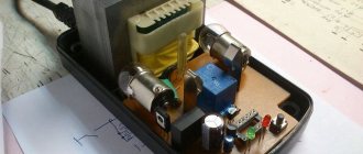
It’s a little more complicated when they also install a timer that turns off the charge after a certain time, but this principle quickly “kills” the batteries. For example, this is done in one of the inexpensive chargers for screwdrivers (photo not mine).
The next class comes from more “smart” chargers, although in essence they are not much better than the previous one. For example, here is a photo of a branded Bosch charger designed to charge NiCd batteries.
But all these chargers seem very simple after looking at the modern options for charging lithium batteries.
Of course, the last option does not quite fit into our concept of redesign, since it is desirable that our charger not only charges correctly, but also costs minimal money.
The chargers of Chinese screwdrivers look, of course, much simpler, but again, hardly anyone would want to make such a device from scratch, although this is exactly what I plan to do in the third part, albeit more correctly.
And so, to begin with, let’s assume that we have a charger on our hands that simply does not fit the new type of battery, but is serviceable. Well, or at least his transformer is working. As I wrote above, you can even use just a resistor or a light bulb, but this is “not our method.”
The schematic diagram of a typical inexpensive charger looks something like this: Transformer, diode bridge, thyristor and control circuit. True, sometimes instead of a thyristor there is a relay, the current is not limited in any way and there may be a thermal control circuit against overheating (although this does not always save.
But from this circuit we only need a transformer and a diode bridge, although we will have to add another capacitor, so we will get some initial unchanged part, it is marked in red and will not change further.
The diode bridge is usually located on the board and can be used if necessary (if it is working properly). Those. By and large, you can remove all radio elements from the board, leaving only four diodes and terminals for connecting the battery, and use the board itself as a base. The cathode of the diodes is marked with a stripe, the point where two terminals marked with a stripe are connected is a plus, respectively, the point of connection of the “unlabeled” terminals is a minus. A transformer is connected to the other two connection points.
True, when you open the charger, you can see the following picture (ignore the absence of a transformer): In this case, you will have to unsolder everything.
It is convenient to replace the diodes on the board with a ready-made diode bridge; a transformer is connected to the speaker terminals, + and -, respectively, go further into the circuit. Of course, you can tell how to choose a capacitor, but I advise you not to bother and put one like in the photo, capacity 1000 μF, voltage 35 Volts. The capacity can be larger, for example 2200, and the voltage is 50 or 63 Volts, a large capacity and voltage do not make sense, but will only increase the size of the capacitor. Any capacitor can be used, even a “noname” will do. Yes, it must be installed in any case, regardless of the serviceability of the diode bridge.
Now let’s move on to the charger itself, or rather to its variants; this node is marked with a rectangle in the last diagram. The simplest and at the same time relatively correct way is to install an LM317 voltage stabilizer chip.
But as I wrote above, the charge current must be limited. Yes, many circuits can not only limit, but also stabilize it, but by and large it does not matter to batteries whether the charge current is 1, 2 or 3 Amperes, it does not matter whether it is stable during the charging process or “floating”, it is important that the charge current does not exceed installed for batteries. Although for batteries that are used in screwdrivers it is difficult to exceed it, since they can operate not only at high discharge currents, but also at high charging currents. The simplest solution is to transfer the LM317 microcircuit from voltage stabilization mode to current stabilization mode, or more precisely, add a current stabilization mode. This is achieved by adding one resistor, as shown in the diagram. The resistor value is very easy to calculate: 1.25/I (current in Amperes) = R (resistor value in Ohms). For example, you need a current of 1.5 Amperes, then it will be 1.25/1.5= 0.83 Ohms.
The values of the voltage divider resistors are also quite easy to calculate, but I would advise placing a trimmer in series with the upper resistor in order to accurately set the voltage, since, unlike current, accuracy is important here. You can use a special calculator, but it is not very convenient, so I will offer values without it, for a voltage of 12.6 Volts (3 series batteries of 3.7 Volts) the upper resistor needs 1.5 kOhm, the trimmer in series with it is 200 Ohm, and the lower resistor is 13 kOhm.
I specifically indicated that the tuning resistor is placed in series with the upper resistor. In the event of a break, the output will have a minimum voltage. If you cut off the lower resistor, the output voltage will be maximum. By the way, in common DC-DC converter boards, the opposite is done; in the event of a break in the trimming resistor, they will output the maximum voltage.
Everything is good in the above scheme, simplicity, price, but the high power output negates all the advantages, since you will need a very impressive radiator, so it is not very suitable for high charging currents.
A more correct option would be to use a step-down DC-DC converter. For example this:
Of course, in its original form it will not limit the current, but if desired, it can be modified (in case it already exists). The modification is simple and I already described it in one of my reviews, although at the end I used it as an LED driver, but essentially it doesn’t matter. You need: 1 transistor type BC557 or any analogue (or even the well-known KT361 or KT3107) 2 resistors with a nominal value of 33-200 Ohms of any power. 1 resistor as a current shunt 1 ceramic capacitor 0.1 µF.
The current measuring resistor is calculated very simply, as in the case of LM317, only the values are slightly different. 0.6/I (current in Amps) = R (resistor value in Ohms). For example, you need a current of 1.5 Amperes, then it will be 0.6 / 1.5 = 0.4 Ohms.
The output of the additional circuit is connected to pin 4 of the LM2596 microcircuit; if another microcircuit is used, then we look for the pin marked as FB in the description and connect it to it.
In this embodiment, using a trimming resistor, we set the output voltage (at idle). True, such a scheme may slightly undercharge the batteries, although not much, but this is the price to pay for simplicity. To charge fully, you need to switch the voltage measurement input (one of the voltage divider resistors) to the output of the entire circuit.
All of the above charging methods are workable, but not very convenient. It would be more correct to use a board that “can” not only stabilize the output voltage, but also the current. For example, this scarf. It is very easy to distinguish suitable boards from others; the description should say “DC-DC StepDown”, and the board should have at least two interlinear resistors.
But in addition to adjusting the output current, this board has an additional bonus in the form of an indication: 1. An LED at the top shows the current limiting mode 2. A pair of LEDs at the bottom shows the end of the charge.
The battery charge indication is implemented very simply; the LEDs switch when the current drops below 1/10 of the initially set one. This mode of operation is very common and is used in many simple chargers. Those. for example, we set the charge current to 1.5 Amperes, connected the battery, when the charge current drops below 150 mA, one of the LEDs will go out and the second will light up, thereby indicating that the charging process is complete. Reviews of this board were done by a colleague of ksiman, so it’s easier to provide a link for a more detailed description.
The diagram of this board, also from the above review, may be useful.
It turns out that this board is quite well suited for charging batteries; first we set the end of charge voltage at the rate of 4.2 Volts per element, and then the charge current. For gourmets, you can offer the same board, but with an indication of the charge current and voltage on the battery, but in my opinion, in this case this is unnecessary. I reviewed this board, in fact this is a photo from that review, where I also showed how to make a switching power supply yourself.
This is what this option will look like on a block diagram.
So we slowly got to the subject of the review, which was primarily of interest due to its low price. I have very strong suspicions about the “proprietary” nature of the installed microcircuit, but if you do not use it for the entire declared 3 Amperes, then it is quite viable.
It so happened that initially I did not think of doing a review of this board, and although I bought 4 of them, I only had one left at home, and that one already had traces of my intervention. I desoldered the original LEDs and soldered others.
In its original form, there are three LEDs on the board: 1. Charged. 2. Charge 3. Current limit indication.
How does the indication work? The Charge and Charged LEDs are turned on so that only one of them lights up, so they can be considered as one. In boards without current regulation at which the indication will be triggered, switching occurs when the charging current drops below 1/10 of that set by the resistor - Current limitation. In the board under review, you can set an arbitrary operating current; I would recommend setting it to 1/5.
The current limit indication LED works slightly differently; it lights up when current limitation occurs, i.e. when the current at the set voltage tends to increase more than that set by the regulator. For example, we set the current to 1 Ampere and 10 Volts (conditionally), connected a load that at 10 Volts consumes 0.5 Amperes. The output will be 10 Volts 0.5 Amperes. Then we connected a load, which at 10 Volts will consume 1.5 Amperes, the output will be 1 Ampere and 8 Volts (conventionally), i.e. the board will reduce the voltage to a value at which the output current will not exceed the set one and at the same time the LED will light up.
There are also three trimming resistors on the board: 1. Adjustment of the output voltage. 2. Adjustment of the threshold for indicating the end of charge. 3. Adjustment of the output current limit threshold.
The board is very simple; it contains the LM2596 chip itself, a 78L05 stabilizer and an LM358 comparator. LM2596 is actually a PWM controller. 78L05 is used to power the comparator and as a voltage reference. LM358 “monitors” the current and simultaneously controls the display
A track on a printed circuit board acts as a current shunt. This method of measuring current is not very good, since the current will “float” depending on the temperature of the board, but since the stability of the output current does not matter for us, we can ignore this.
Location of contacts, controls and indications from the product page.
Boards with the ability to limit output current are very suitable for charging batteries. And those boards that have an indication of the end of the charge also allow you to get some convenience, allowing you to know that the battery is charged. But all of the above methods have one drawback: all these options cannot turn off the battery after charging is complete, i.e. stop the process completely. Of course they will tell me how the batteries live in uninterruptible power supplies. But here there is a peculiarity: some types of batteries have a concept - cyclic charging and the so-called Standby, i.e. supportive. The same lead battery is charged in cyclic mode to 14.3-15 Volts, and in standby mode only to 13.8-13.9 Volts.
If the battery is not disconnected, then a small charging current will always flow through it, and although lithium batteries are a little “lucky” in this regard, their current drops very significantly, but still, it is not recommended to leave them in this mode. The fact is that cadmium or lead ones simply begin to break down, heat up and that’s it, but with lithium ones a fire is possible. Yes, lithium batteries have a safety valve, but extra protection is never a bad thing.
The question is often asked - what about the protection board, because it can turn off the battery after charging is complete. It can and not only can, but it will turn it off, only it will do this not at 4.2 Volts per element, but at 4.25-4.35 Volts, since the shutdown function for it is more protective than the main one. Therefore, doing this is highly not recommended.
That’s actually why I came up with a simple circuit that will turn off the battery when the charge is complete. The operating principle is very simple (and therefore has some limitations). We connected the battery, since capacitor C1 is discharged, a current flows through it, which opens the transistor, and it supplies current to the relay. The relay connects to the charging battery, and then the relay is powered through an optocoupler, which is connected to the charge indication output of the converter board.
Accordingly, a small scarf was developed, and in a universal design.
Well, then everything is simple and familiar, we print the board on paper, transfer it to the PCB, and etch it. For those interested, the process of manufacturing printed circuit boards is shown in detail in this review.
When I came up with the circuit, I tried to simplify it as much as possible, using a minimum of components. 1. Relay - any with a winding voltage of 12 Volts (for options with 3-4 batteries) and contacts designed for a current of at least 2x the charging current. 2. Transistor - BC846, 847, or the well-known KT315, KT3102, as well as analogues. 3. Diode - any low-power diode. 4. Resistors - any in the range of 15 - 33 kOhm 5. Capacitor - 33-47 uF 25-50 Volts. 6. Optocoupler - PC817, found on most power supply boards.
Collected the fee.
I made the board universal; you can use a field-effect transistor instead of a relay; some of the components remain the same as before. In addition, this option is more universal, as it is suitable for screwdrivers with 3-4-5 batteries. But this board has a drawback. There is a “parasitic” diode inside the transistor, and if you leave the battery connected to the charger but unplug it, the battery will discharge through the charger circuit. In the version that I showed above, there will be a similar problem, but there the current is very small, about 0.5 mA, and it will take about 4000 hours for the battery to completely discharge.
Slightly different values are used here, although essentially only the value of resistors R4 and R5 is important. The value of R5 must be at least 2 times less than that of R4.
We select components for the future board. Unfortunately, you will most likely have to buy a transistor, since such devices are rarely used in finished devices; they can be found on motherboards, but extremely rarely.
The board is universal, you can use a relay and make it according to the previous circuit, or you can use a field-effect transistor.
Now the block diagram of the charger will look like this: Transformer, then diode bridge and filter capacitor, then the DC-DC converter board, and finally the shutdown board. I did not sign the polarity of the charge indication pins, since it can be different on different boards; if something doesn’t work, then you just need to swap them, thereby changing the polarity to the opposite.
Let's move on to the actual alteration. First of all, I cut the tracks from the output of the diode bridge, the battery connection terminals and the charge indication LED. The goal is to disconnect them from the rest of the circuit so it doesn't interfere with the "process". You can, of course, simply unsolder all the parts except the bridge diodes, it will be the same, but it was easier for me to cut the tracks.
Then we solder the filter capacitor. I soldered it directly to the diode terminals, but you can install a separate diode bridge, as I showed above. Remember that a terminal with a stripe is a plus, without a stripe a minus. The capacitor has a long lead - a plus.
The printed circuit boards on top did not fit at all, constantly resting against the top cover, so we had to place them from below. Here, of course, everything was not so smooth, they had to bite out one stand and saw down the plastic a little, but in any case, they were much better here. They even increased in height with a margin.
Let's move on to the electrical connections. To begin with, we solder the wires, at first I wanted to use thicker ones, but then I realized that I simply couldn’t turn around with them in a cramped case and took ordinary multi-core wires with a cross-section of 0.22mm.sq. I soldered the wires to the top board: 1. On the left is the power input of the converter board, connected to the diode bridge. 2. On the right - white and blue - the output of the converter board. If a disconnect board is used, then to it, if not, then to the battery contacts. 3. Red with blue - output indicating the charging process, if with a shutdown board, then to it, if not, then to the indication LED. 4. Black with green - Indication of the end of the charge, if with a disconnect board, then to the LED, if not, then we do not connect it anywhere.
So far only the wires to the battery are soldered to the bottom board.
Yes, I completely forgot, you can see the LED on the left board. The fact is that I completely forgot and unsoldered all the LEDs that were on the board, but the problem is that if you unsolder the current limit indication LED, the current will not be limited, so it must be left (marked on the board as CC/CV) , be careful.
In general, we connect everything as shown, the photo is clickable.
Then we glue double-sided tape to the bottom of the case, since the bottom of the boards is not entirely smooth, it is better to use thick tape. In general, everyone does this moment as conveniently as possible, you can glue it with hot glue, screw it with self-tapping screws, nail it 
We glue the boards and hide the wires. As a result, we should have 6 wires left free - 2 to the battery, 2 to the diode bridge and 2 to the LED.
Don’t pay attention to the yellow wire, this is a special case, I only had a 24 Volt relay, so I powered it from the converter input. When preparing wires, always try to follow the color coding, red/white is positive, black/blue is negative.
We connect the wires to the original charger board. Here, of course, everyone will have their own way, but I think the general principle is clear. You need to especially carefully check that the connection to the battery terminals is correct; it is better to first check with a tester where the plus and minus are; however, the same applies to the power input.
After all these manipulations, it is imperative to check and possibly reset the output voltage of the converter board, since during the installation process you can reset the setting and get at the output not 12.6 Volts (the voltage of three lithium batteries), but for example 12.79. You can also adjust the charge current.
Since setting the threshold for indicating the end of charge is not very convenient, I recommend buying a board with two trimming resistors, it’s easier. If you bought a board with three trimming resistors, then to configure it you need to connect to the output a load approximately corresponding to 1/10 - 1/5 of the set charge current. Those. if the charge current is 1.5 Amperes and the voltage is 12 Volts, then it can be a resistor with a nominal value of 51-100 Ohms with a power of about 1-2 Watts.
We've set it up and check it before assembly. If you did everything correctly, then when you connect the battery, the relay should activate and the charge will turn on. In my case, the indication LED goes out and turns on when the charge is complete. If you want to do the opposite, you can turn on this LED in series with the input of the optocoupler, then the LED will light while charging is in progress.
Since the title of the review still mentions the board, and the review is about redesigning the charger, I decided to check the board itself. After half an hour of operation at a charge current of 1 Ampere, the temperature of the microcircuit was about 60 degrees, so I can say that this board can be used up to a current of 1.5 Amperes. However, I suspected this from the very beginning; at a current of 3 Amps, the board will most likely fail due to overheating. The maximum current at which the board can still be used relatively safely is 2 Amperes, but since the board is in a case and the cooling is not very good, I recommend 1.5 Amperes.
That's it, we twist the body and set it to full run. I actually had to drain the battery before this, since I charged it in the process of preparing the last part. If a charged battery is connected to the charger, then the relay is activated for 1.5-2 seconds, then turns off again, since the current is low and blocking does not occur.
So, now about the good and the not so good. The good thing is that the conversion was a success, the charge is on, the board disconnects the battery, in general it’s simple, convenient and practical. The bad - If you turn off the charger's power during charging and then turn it on again, the charge will not automatically turn on. But there is a much bigger problem. During the preparation process, I used the board from the previous review, but I also wrote there that the board does not have a controller, and therefore cannot be completely blocked. But smarter boards completely turn off the output in a critical situation, and since it is also an input, when connected to the charger that I modified above, it will not start. Voltage is needed to start, and the board needs voltage to start 
There are several solutions to this problem. 1. Place a resistor between the input and output of the protection board, through which current will flow to the terminals to start the charger, but I don’t know how the protection board will behave, there is nothing to check. 2. Connect the charger input to a separate battery terminal, this is often done with cordless tools with lithium batteries. Those. We charge through some contacts, discharge through others. 3. Do not install a shutdown board at all. 4. Instead of automation, install a button as in this diagram.
At the top there is an option without a protection board, at the bottom there is just a relay, an optocoupler and a button. The principle is simple, we inserted the battery into the charger, pressed the button, the charge began, and we went to rest. Once the charge is complete, the relay will completely disconnect the battery from the charger.
Conventional chargers constantly try to supply voltage to the output if it is below a certain value, but this modification option is inconvenient, and with a relay it is not very applicable. But for now I think it might be possible to do it beautifully.
What can you advise regarding the choice of battery charging options: 1. Just use a board with two trimming resistors (it is in the review), it’s simple, quite correct, but it’s better not to forget that the charger is on. I don’t think there will be any problems for a day or two, but I wouldn’t recommend going on vacation and forgetting the charger is on. 2. Do as in the review. Difficult, with limitations, but more correct. 3. Use a separate charger, for example the well-known Imax. 4. If your battery has an assembly of two or three batteries, then you can use B3. It is quite simple and convenient, in addition, there is a full description in this review from the author Onegin45.
5. Take the power supply and modify it a little. I did something similar in this review.
6. Make your own charger, with all automatic shutdowns, correct charging and extended display. The most difficult option. But this is the topic of the third part of the review, however, it will most likely also include converting the power supply into a charger.
7. Use a charger like this.
In addition, I often encounter questions about balancing the elements in the battery. Personally, I think that this is unnecessary, since high-quality and selected batteries are not so easy to unbalance. If you want something simple and high quality, then it’s much easier to buy a protection board with a balancing function.
Recently there was a question whether it is possible to make the charger able to charge both lithium and cadmium batteries. Yes, it can be done, but it’s better not to, since in addition to different chemistry, batteries also have different voltages. For example, an assembly of 10 cadmium batteries requires 14.3-15 Volts, and an assembly of three lithium batteries requires 12.6 Volts. In this regard, you need a switch that you can accidentally forget to switch. A universal option is only possible if the number of cadmium batteries is a multiple of three, 9-12-15, then they can be charged as lithium assemblies 3-4-5. But common tool batteries cost assemblies of 10 pieces.
That seems to be all, I tried to answer some questions that people ask me in private. In addition, the review will likely be supplemented with answers to your next questions.
The purchased boards are quite functional, but the chips are most likely fake, so it is better to load no more than 50-60% of the declared value.
In the meantime, I’m thinking that you need to have it in a proper charger, which will be made from scratch. So far the plans are: 1. Automatic start of charging when installing the battery 2. Restart in case of power failure. 3. Several stages of charging process indication 4. Select the number of batteries and their type using jumpers on the board. 5. Microprocessor control
I would also like to know what would be interesting for you to see in the third part of the review (you can PM me).
I wanted to use a specialized microcircuit (it seems that you can even order a free sample), but it only works in linear mode, and this causes heating :((((
It might be useful to have a link to an archive with traces and diagrams, but as I wrote above, the additional board most likely will not work with boards that completely disconnect the batteries.
In addition, such conversion methods are only suitable for batteries up to 14.4 Volts (approximately), since chargers for 18 Volt batteries produce voltages above 35 Volts, and DC-DC boards are designed only up to 35-40.
Application of LM7805 regulator
The charger circuit for a screwdriver with an LM7805 regulator includes only two-channel microcircuits. Capacitors are used on it with a capacity of 3 to 10 pF. You can most often find regulators of this type in models of the Bosch brand. They are not suitable for 12V chargers directly. In this case, the negative resistance parameter in the circuit reaches 30 Ohms.
If we talk about transistors, then they are used in models of the pulse type. Triggers for regulators can be used. There are three diodes in the circuit. If we talk about 14 V modifications, then tetrodes are only suitable for them of the wave type.
Operating principle of the charger
If a memory device fails, it makes sense to first try to restore it. To carry out repairs, it is advisable to have a charger circuit and a multimeter. The circuitry of many charging devices is based on the HCF4060BE microcircuit. Its switching circuit forms the delay of the charging time interval. It includes a crystal oscillator circuit and a 14-bit binary counter, making it easy to implement a timer.
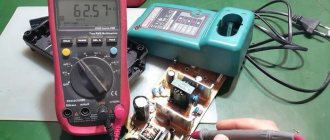
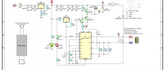
The operating principle of the charger circuit is easier to understand using a real example. This is what it looks like in an Interskol screwdriver:
This circuit is designed to charge 14.4-volt batteries. It has an LED indication showing the connection to the network, LED2 is lit, and the charging process, LED1 is lit. The U1 HCF4060BE chip or its analogs: TC4060, CD4060 are used as a counter. The rectifier is assembled on power diodes VD1-VD4 type 1N5408. PNP transistor type Q1 operates in key mode; the control contacts of relay S3-12A are connected to its outputs. The operation of the key is controlled by controller U1.
When the charger is turned on, the alternating voltage of 220 volts is supplied through a fuse to a step-down transformer, at the output of which its value is 18 volts. Then, passing through the diode bridge, it is straightened and falls on a smoothing capacitor C1 with a capacity of 330 μF. The voltage across it is 24 volts. When connecting the battery, the relay contact group is in the open position. The U1 microcircuit is powered through a zener diode VD6 with a constant signal of 12 volts.
When the “Start” button SK1 is pressed, a stabilized signal is supplied to the 16th pin of the controller U1 through resistor R6. Key Q1 opens and current flows through it to the relay terminals. The contacts of the S3-12A device close and the charging process begins. The VD8 diode, connected in parallel to the transistor, protects it from a voltage surge caused by the relay turning off.
The SK1 button used works without fixing. When it is released, all power is supplied through the chain VD7, VD6 and limiting resistance R6. And also power is supplied to LED1 through resistor R1. The LED lights up, signaling that the charging process has begun. The operating time of the U1 chip is set to one hour of operation, after which power is removed from the transistor Q1 and, accordingly, from the relay. Its contact group breaks and the charging current disappears. LED1 goes out.
Using BC847 transistors
The charger circuit for the BC847 transistorized screwdriver is quite simple. These elements are used most often. They are suitable for 12 mAh batteries. In this case, the microcircuits are of a three-channel type. Capacitors are used with dual diodes.
The triggers themselves are of the open type, and their current conductivity is at the level of 5.5 microns. A total of three transistors are required for charging at 12 V. One of them is installed near the capacitors. The rest in this case are located behind the reference diodes. If we talk about voltage, then 12 V charges with these transistors can handle overloads of 5 A.
Types of batteries
Batteries are of different types and their charging modes may be different. Nickel-cadmium (Ni-Cd) batteries are a very good source of energy and are capable of delivering high power. However, for environmental reasons their production has ceased and they will become less and less common. Now they have been replaced everywhere by lithium-ion batteries.
Sulfuric acid (Pb) lead gel batteries have good characteristics, but they make the tool heavier and therefore are not very popular, despite their relative cheapness. Since they are gel (the sulfuric acid solution is thickened with sodium silicate), there are no plugs in them, the electrolyte does not leak out of them, and they can be used in any position. (By the way, nickel-cadmium batteries for screwdrivers also belong to the gel class.)
Lithium-ion batteries (Li-ion) are now the most promising and promoted in technology and on the market. Their feature is the complete sealing of the cell. They have a very high power density, are safe to use (thanks to the built-in charge controller!), can be disposed of favorably, are the most environmentally friendly, and are lightweight. They are currently used very often in screwdrivers.
Transistor device IRLML2230
Charging circuits with transistors of this type are found quite often. uses them in 14 and 18 V versions. In this case, the microcircuits are used only of the three-channel type. The direct capacity of these transistors is 2 pF.
They tolerate current overloads from the network well. In this case, the conductivity indicator in the charges does not exceed 4 A. If we talk about other components, then the capacitors are installed of the pulse type. In this case, three of them will be required. If we talk about 14 V models, then they have thyristors for voltage stabilization.
DIY universal charger
To charge the battery device, you can make a homemade charger powered by a USB source . Necessary components for this: socket, USB charger, 10 amp fuse, necessary connectors, paint, electrical tape and tape. To do this you need:
- Disassemble the screwdriver into parts and cut off the upper body from the handle with a knife.
- Make a hole for the fuse on the side of the handle. Connect the wire to the fuse and install it in the handle of the unit.
- Secure the fuse with glue or a heat gun. Wrap the housing with tape and attach the structure to the battery connector. The wires are mounted at the top of the screwdriver. The tool is assembled and wrapped with electrical tape. After which the case is sanded, coated with paint and the resulting device is charged.
As you can see, this process will not take much time and will not be too ruinous for your family budget.
Source: instrument.guru