Review of the optical theodolite UOMZ 4T30P
9
Optical theodolite 4T30P is one of the most famous domestic geodetic instruments - a device produced by the Ural Optical-Mechanical Plant. Depending on the principle of operation, theodolites can be divided into the following groups:
- mechanical (with mechanical sighting systems);
- optical (with optical reading devices);
- electronic (with microprocessors and control panel);
— in terms of measurement accuracy:
- technical,
- accurate,
- high precision;
— by area of application:
- construction,
- military,
- astronomical,
- mine surveying
Optical theodolite 4T30P is an optical-mechanical geodetic device and belongs to the instruments of technical precision. The 4T30P optical theodolite is used to obtain the values of horizontal and vertical angles during geodetic production, for linear measurements using a grid of threads, and it is possible to use a geodetic instrument to determine magnetic azimuths along a compass. In the vertical plane, the 4T30P optical theodolite determines the angles of inclination and zenith distances. To obtain angles in the horizontal plane, the method of measuring one angle and the method of circular techniques are used. This geodetic device is used for work that ensures the technical accuracy of the results, during construction work and engineering surveys, reconnaissance work, and is very convenient for expeditions. Advantages of the optical theodolite 4t30p: - a scale microscope is used to take readings; — the ability to use a three-arm method using a removable stand, which has a built-in optical plummet; - has a direct image telescope; — by rotating a special screw of a geodetic instrument, the dial is rearranged; — there is a removable tribrach; — the use of the tool is possible in different climatic zones; - has small dimensions and weight.
The 4T30P theodolite device provides a square measurement error in one step of 20″ for a horizontal angle and 30″ for a vertical angle.
Geodetic instruments are simple and easy to use, and have a high speed of reading. When performing measurements, a surveying tripod S6-Z, a built-in optical plummet, and a flashlight are used to illuminate the microscope scale.
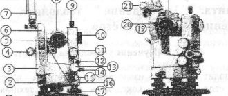
Optical theodolite device 4T30P
I - ratchet; 2 — pipe fixing screw; 3 — microscope eyepiece; 4 — telescope; 5 — illumination mirror; 6 - column; 7 — stand; 8 — dial adjustment handle; 9 — alidade fixing screw; 10 — adjustment screw; II — diopter eyepiece ring; 12 — cap; 13 — level with alidade; 14 — alidade guide screw; 15 — pipe guide screw; 16 — sighting device In the column camps of the 4T30P 6 optical theodolite, a horizontal axis is installed, which represents a single whole with the body of the telescope. Using the collimator sights of the geodetic instrument 16, rough aiming is carried out at the target. To accurately point the telescope at the target, the aiming screw 14 is used after fixing the alidade in the horizontal plane with screw 9, and the aiming screw 15 after fixing it in the vertical plane with screw 2. The scale division of the horizontal and vertical circles of the 4T30P optical theodolite is 1°. The images of the scales of both circles of the geodetic instrument are transferred to the field of view of the microscope when the diopter ring is rotated until a clear image of the strokes of the eyepiece 3 is made. Readings are made using the scales of the microscope. Optimal illumination of the field of view is achieved by tilting and rotating mirror 5. The dial stroke of the 4T30P optical theodolite serves as the basis for the reading, which is taken with an accuracy of 0.5′. The geodetic instrument set includes: - a level that is necessary for geometric leveling. The level is attached to the telescope instead of the collimator sight 4; — the reference compass of the 4T30P optical theodolite is used to determine magnetic azimuths; - eyepiece attachments, which are used to more conveniently see objects and are attached to the telescope. Before performing work, it is necessary to carry out all verifications of the geodetic instrument. To prepare the instrument for observations, you need to perform: 1) centering; 2) bring the main axis of the device into a vertical position; 3) install a telescope for sighting. Geodetic equipment of this class is extremely easy to use and enjoys well-deserved respect and popularity in its segment.
9
Checking and adjusting theodolite 4T30 and ZT5KP.
Main axes of theodolite 4T30P (Fig. 5):
Rice. 5. Scheme of the main axes of theodolite I-I1 – vertical axis (axis of rotation of the alidade of the horizontal circle);
H-H1 – horizontal axis (axis of rotation of the telescope);
u-u1 – axis of the cylindrical level of the horizontal circle (tangent to the inner surface of the level at its zero point);
V-V1 – sighting axis (straight line passing through the optical center of the lens and the center of the reticle) Basic conditions that must be met in a theodolite when measuring angles: the vertical axis of the device must be plumb and the sighting plane is vertical. Compliance with these conditions is essential for the accuracy of angular measurements. During the operation and transportation of the theodolite, the correct location of the main axes may be disrupted, which necessitates regular checks and, if necessary, adjustments of the theodolite, performed in a certain sequence.
1. The axis of the cylindrical level u-u1 of the horizontal circle must be perpendicular to the vertical axis I-I1 of the device.
The alidade is positioned so that the axis of the level being checked is parallel to the two lifting screws, and with these screws the bubble of the level is brought to the zero point. Rotate the alidade (with the dial fixed), and with it the level being checked, by 180°. The verification scheme is shown in Fig. 6, a.
If the level bubble remains at the zero point or deviates from it by no more than one division, the condition is met. Otherwise, the corrective level screws move the bubble by half the deviation, and the second half of the deviation is eliminated with lifting screws. These actions are repeated until the verified condition is met.
The vertical axis of the theodolite is brought into a vertical position as follows. The level is set in the direction of the two lifting screws and the level bubble is brought to the zero point. The alidade is turned 90°, and the bubble is again brought to the middle by the third lifting screw. These steps are repeated until the bubble moves away from the middle by more than one division.
2. The sighting axis of the telescope V-V1 must be perpendicular to the rotation axis of the telescope H-H1.
The angle of deviation of the sighting axis of the pipe from the perpendicular to the horizontal axis H-H1 of the theodolite is called the ollimation error c.
4. The vertical stroke of the thread grid must be parallel to the vertical axis I-I1 of the theodolite.
If there is an optical plummet, it is verified.
5. The axis of the optical plummet must be parallel to the vertical axis of the theodolite.
Having installed the theodolite on a tripod in the working position, mark the projection of the center of the optical plummet grid on a sheet of paper placed under the tripod. After releasing the alidade fixing screw, rotate the theodolite.
If the displacement of the center of the plummet grid relative to the marked point exceeds the permissible value (0.5 mm), half the displacement is corrected with the grid adjustment screws and the verification is repeated.
Adjustment of theodolite 3T5KP
9.2.1 Adjusting the mirror of the reading device. If the illumination mirror of the reading microscope does not retain its assigned position, increase the friction in the hinges with two adjusting screws compressing the slot in the mirror frame.
9.2.2 Elimination of parallax and ren of the reading device. If a sharp image of the dial strokes is achieved at one position of the microscope eyepiece, and sharpness of the reference scale strokes is achieved at another, eliminate the parallax as follows: remove cover 3 (see Fig. 2), which opens access to two brackets in which the microscope objective lenses of the horizontal and vertical circles are located.
9.2.3 Level adjustment. If, when checking the cylindrical level, the displacement of the bubble exceeds one division, correct half of the displacement with the lifting screw of the stand, and the other half with the adjusting screw.
9.2.4 Elimination of residual displacements of the tripod and stand.
9.2.5 Eliminating the tilt of the telescope reticle.
9.2.6 Adjusting the compensator.
9.2.7 Correction of collimation error and zero point of the vertical circle.
9.2.8 Adjustment of collimator sights.
9.2.9 Adjustment of the plummet.
9.2.10 Elimination of systematic compass errors:
— set the sighting axis of the theodolite being tested along the magnetic meridian, using the value of the magnetic azimuth of the reference taken as true;
— loosen the fastening of the compass body to bracket 2 (see Fig. 8) by slightly unscrewing two screws on its lower part, and by turning the compass body relative to the bracket, align the ends of the arrows with the compass indices;
— fasten the compass body with the bracket and repeat the check.
Types of devices
The following types of devices are available:
- Mechanical . It is the simplest in design and the cheapest type, but it also has the lowest accuracy, so it is not suitable for serious work.
- Electronic . An electronic theodolite is convenient because it is equipped with a device for reading and processing the results; the surveyor just needs to set it correctly, and the device will do the rest itself.
- Optical . The most widely used is the optical theodolite. It does not perform calculations like an electronic one, but the cost of the device and the quality of measurements are attractive.
- Laser . These theodolites are the most expensive, but also more advanced devices. They allow you to take measurements with great accuracy and are convenient to use, but it makes sense to purchase them only for regular work, where the requirements for the result are high.
Two fundamentally different types of theodolites differ in the mobility of the alidade and limb. In repeating types, these elements can be fixed one by one, and readings can be taken using the method of sequential repetitions. Ordinary options do not allow this, since the alidade with the axis represents a single fixed whole, and each measurement requires a separate setting.
Requirements before work
Before measuring angles, the theodolite is checked . It is necessary to check the special mark or seal, as well as periodically check the geometric parameters, since an error of a couple of degrees can lead to disaster over time!
- What is important is the absolute verticality of the alidade axis and its perpendicularity to the cylindrical level.
- The sighting axis of the telescope must be perpendicular to it; without fulfilling this collimation condition, a clear reference system is impossible.
- The axes of the pipe and alidade must be perpendicular.
- We check to what extent the measuring grid is located in the vertical collimation plane.
Using a theodolite
There are many techniques for professional use of devices, and they are taught in special courses, here we present the main ones.
- Installation of theodolite. The first step is to find a starting point. On the ground, we find a flat surface on which we center the device on the stand with levels and clamping screws. As a result, the position of the device should be strictly horizontal.
- We catch the object. We use the sight to find the target and more accurately aim the measuring grid with the screws to establish the center of the object. We look at this through an eyepiece, and if there is not enough light, a special mirror will help improve the situation (as is the case with a microscope). After setting the center, the eyepiece records its value.
- Processing the results. It is better to take not one, but several measurements. A new reading is recommended to a known value, for example 90°. If the new measurements differ from the previous ones by 90°, then the result can be recorded; if not, a couple more similar measurements are made with different readings and the average value is calculated.
Completeness
| Name of components | Quantity, pcs |
| Theodolite | 1 |
| Case | 1 |
| Stand | 1 |
| Pipe level | 1 |
| Eyepiece attachments: | |
| on the spotting scope | 1 |
| on a microscope | 1 |
| Screwdriver large | 1 |
| Small screwdriver | 1 |
| Large hairpin | 1 |
| Small hairpin | 1 |
| Oil can with oil | 1 |
| Passport | 1 |
| Additional accessories | |
| Flashlight | 1 |
| Landmark compass | 1 |
| Case | 1 |
| Note - The list of additional devices is determined by the agreement between the consumer and the supplier. | |
Specifications
| Parameter name | Parameter value |
| Permissible root mean square error of measuring the horizontal angle in one step, no more | 20″ |
| Permissible root mean square error of measuring the vertical angle (zenith distance) in one step, no more | 30″ |
| Vertical angle measurement range | from minus 55° to plus 60° |
| Spotting scope | |
| - image | direct |
| - increase | (20-i) x |
| - angular field of view | (2.0-0.i) ° |
| — shortest sighting distance without lens attachment, m, no more | 1,2 |
| — the shortest sighting distance with a lens attachment, m, no more | 0,5 |
| — thread rangefinder coefficient | 100 ± 0,5 |
| Limb division price | 1° |
| Microscope scale division price | 5′ or 1′ |
| Level division price for alidade | 45″ |
| Level division price for pipe | 20″ |
| Weight of theodolite with stand, kg, no more | 2,3 |
| Overall dimensions, mm, no more than: theodolite (with the middle position of the lifting screws of the stand) case | 140x130x230 285x245x220 |
| Operating ambient temperature range, °C | from minus 40 to plus 50 |
| Service life, years, not less | 6 |
Main parts of theodolite
The device allows you to measure angles in space with high accuracy and work in a horizontal or vertical plane. As a rule, a relative method is chosen, when a reference object is taken as a basis, and the desired angle is already calculated from it. Measuring in this way has been known since the 19th century, but today's theodolites are improved devices, of which there are several varieties .
Scale . This element, represented by a horizontal or vertical circle, shows the result. It is located on a stand that has adjusting screws for controlling the main components. The meter looks into the eyepiece, which is controlled by screws that allow the eyepiece to be aimed at an object and secured when a reference point is found.
Limbo and alidade . Parts of a horizontal circle that are actively used when measuring horizontal angles.
- The dial is a stationary glass ring with 360° divisions.
- Alidade is an element that rotates with the adjacent part of the device and provides a reading.
To fix the reading and carry out further measurements relative to it, a special screw is fixed and the dial is released; in this case, the body will remain motionless, but the dial and alidade will move.
These are the main parts of the theodolite. But other devices also help take readings, which will also be useful to get to know. The degree of horizontality of the theodolite installation is controlled using a cylindrical level, and an optical plummet prevents you from losing the reference point. Readings are taken using a microscope, and this is the final stage of the measurer’s work.
Description
Theodolites 4T30P belong to optical scale theodolites of technical accuracy. Depending on the microscope scale division, the theodolite is manufactured in two versions.
Theodolites 4T30P are made in the form of a single optical-mechanical unit, which includes a direct image telescope with a filament rangefinder, a combined reference system for horizontal and vertical angles, and liquid levels for installing the device in the working position.
Theodolites are equipped with a removable stand with a built-in plummet and a horizontal circle translation mechanism. The level with the telescope allows you to perform leveling work.
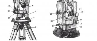
Scheme for sealing theodolite 4T30P from unauthorized access:
Mil A
tt
Figure 1 — Theodolite 4T30P (left and right views)
To prevent unauthorized access to the internal parts of the 4T30P theodolite, upon release from production, screws “A” and “B” of the side covers, as well as cases with packed parts of the kit, are sealed.
The verification mark is applied to the verification certificate.