As a complex geodetic instrument designed to ensure high accuracy of angular measurements, the theodolite must always be correctly configured, and its characteristics must exactly correspond to those declared by the manufacturer. For obvious reasons, during operation and/or transportation of the device, the location of the main instrument axes may be distorted.
The main goal of regular instrument verification procedures is to identify deviations of the instrument from compliance with geometric conditions and optical or mechanical parameters of individual components and mechanisms - instrument constant, necessary corrections and errors, etc.
Adjustment (adjustment) is a sequence of actions that maximally corrects problems, errors, and deviations identified during the verification process.
Theodolites alignment procedure
The correct implementation of checks and adjustments required for correct operation of the device is determined by two points:
- the mounting, lifting, fastening, guiding (micrometer) and correction (adjusting) screws that make up the system of screws must rotate smoothly, providing a small stroke to the moving parts of the tool;
- The alidade of the horizontal limb should move smoothly.
Based on the results of the analysis and the settings made, the further suitability of the tool for carrying out work of the declared accuracy is revealed.
The key steps for checking and adjusting a theodolite are as follows:
- Bringing the device into working position, which includes centering, leveling and focusing the telescope under the vision of a specific operator in order to obtain a clear display of the reticle and the reference sighting point.
- Checking compliance with the perpendicularity of the axis of the cylindrical level and the vertical axis of the tool. If the verification conditions are not met, the adjustment is performed by bringing the level bubble to the zero point using a lifting screw, and its centering at the zero point using the corrective screws of the level itself.
- Checking the perpendicularity of the horizontal thread of the thread grid and the vertical axis of the tool. If the conditions are not met, the adjustment consists of loosening the screws of the eyepiece ring and rotating the reticle until a result is achieved in which the movement of the sighting tube does not affect the position of the horizontal thread relative to the reference point. Another equivalent adjustment method could be to align the vertical axis of the thread grid with a thread plumb line located 10-15 meters from the location of the theodolite.
- Checking compliance with the perpendicularity of the axis of rotation of the sighting tube and the vertical axis of the instrument. Verification has a permissible error, exceeding which requires the theodolite to be adjusted by qualified specialists from the service center or metrological authorities.
- Checking that the vertical thread of the thread grid is parallel to the vertical axis of the theodolite. If the verification conditions are not met, the position of the thread grid is corrected using the adjusting screws. After adjustment, you will need to repeat step 4.
Theodolites are checked and adjusted to identify and eliminate errors caused by deviations from the geometric and optical-mechanical requirements inherent in the design of the device.
1. The movement of the lifting screws should be smooth, measured, without rolling or jamming.
Adjust the screw stroke by rotating the adjusting nut in one direction or another using a pin until a uniform screw stroke is achieved.
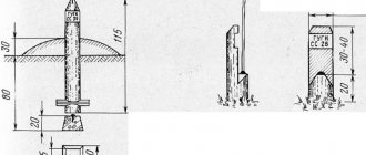
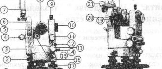
Round level
Rice. 3.22. A rod with a round level according to the microscope, equal to the place
| Technical specifications | TZO | T15 | T15K. | | |
| USSR | ||||
| Mean square error of measurement | 30″ | 10″ | 10″ | |
| horizontal angle from one | ||||
| reception | ||||
| With the method of repetitions of three repetitions | 10″ | 5″ | 5″ | |
| Mean square error of measurement | 20″ | 20″ | 20″ | |
| vertical angles | ||||
| Spotting scope | ||||
| Increase | 20* | 25x | 25x | |
| line of sight | 2° | 1°30′ | 1°30′ | |
| Lens focal length, mm | 157 | 200 | 250 | |
| Exit pupil diameter, mm | 1,35 | 1,4 | 1,4 | |
| Rangefinder thread coefficient | 100 | 100 | 100 | |
| Focusing limits, m | From 1 | From 1.2 | From 1.5 | |
| DO oo | DO oo | DO oo | ||
| Unit counting system | ||||
| Working diameter of horizontal circle, mm | 72 | 76 | 90 | |
| » » vertical circle, mm | 72 | 72 | 70 | |
| Circle division price | 10′ | 1° | 1° | |
| Microscope Magnification | 18x | 72x | 65x | |
| Price of the smallest division of the micro scale | 1′ | 1′ | ||
| osprey | ||||
| Reading accuracy | G | 0,1′ | 0,1′ | |
| Level | ||||
| Level division chain for alidade horizon | 45″ | 45″ | 45″ | |
| tall circle | 15″ | |||
| The price of dividing the level with an alidade of verti | 30″ | |||
| cal circle | ||||
| Round level division price | ||||
| Compensator | ||||
| Compensator range | 3,5′ | |||
| Compensation Accuracy | 2″ | |||
| Optical plummet | ||||
| Increase | 2.5x | 2.5x | ||
| line of sight | 4=30′ | 4° 30′ | ||
| Focusing limits, m | From 0.8 | 0,35 | ||
| up to 2 | DO oo | |||
| Weight | ||||
| Theodolite, kg | 2,2 | 3 | 3 | |
| Case, kg | 1,0 | 3,5 | 3,5 | |
| Tripod, kg | 3,8 | 5,3 | 5,3 | |
| Dimensions | ||||
| Theodolite height, mm | 220 | 250 | 250 | |
| Distance from tripod head to axis | 175 | 210 | 210 | |
| telescope distance, mm | ||||
| T5 | T5K | 2T5 | 2T5K | T2 | 2T2 | 020 | 020 A | |
| USSR | GDR | |||||||
| 6″ | 5″ | 5″ | 5″ | 2″ | 2″ | 3″ | 3″ | |
| 3-4″ | 1″ | 1″ | ||||||
| 8—10″ | 8″ | 8—10″ | 8″ | 2,9″ | 3″ | 6—8″ | 6—8″ | |
| 25x | 27x | 27x | 27.5x | 25x | 27.5x | 25x | 25x | |
| 1°30′ | 1°30′ | 1s30′ | 1°30′ | 1°30′ | 1°30′ | G65′ | ||
| 250 | 218,5 | 218,6 | 218,6 | 250 | 250 | 195 | 175 | |
| 1,4 | 1,4 | 1,4 | 1,4 | 1,4 | 1,4 | |||
| 100 | 100 | 100 | 100 | 100 | 100 | 100 | 100 | |
| From 1.5 | From 2 | From 2 | From 2 | From 1.5 | From 2 | From 2.1 | From 1.5 | |
| DO oo | DO oo | DO oo | DO oo | DO oo | to oo | DO oo | to oo | |
| 90 | 95 | 90 | 90 | 90 | 90 | 96 | 86 | |
| 70 | 70 | 70 | 70 | 65 | 65 | 74 | 86 | |
| 1° | 1° | 1° | 1° | 20′ | 20′ | 1° | 1° | |
| 65x | 70s | 71x | 71.1x | 45.6x | 45.6x | |||
| G | 1′ | 1′ | 1′ | 1.» | 1″ | 1′ | 1′ | |
| o, g | 0,1′ | 0,1′ | 0,1′ | 0,1″ | 0,1″ | 0,1″ | 0,1″ | |
| 45″ | 30″ | 30″ | 30″ | 15″ | 15″ | 30″ | 30″ | |
| 15″ | 15″ | 15″ | 15″ | |||||
| 10′ | 8′ | 8′ | ||||||
| 3,5′ | 3,5′ | 4′ | 4′ | |||||
| 2″ | 2″ | 1″ | 1″ | |||||
| 2.5x | 2.5x | 2.5x | 2.5x | 2.5x | 2.5x | 2.1x | 2.1x | |
| 4°30′ | 4С30′ | 4e 30′ | 4930′ | 4°30′ | 4°30′ | |||
| From 0.35 | From 0.3 | From 0.6 | From 0.6 | From 0.3 | From 0.3 | 0,5 | 0,5 | |
| to oo | DO oo | DO oo | DO oo | DO oo | DO oo | DO oo | to oo | |
| 3,5 | 3,5 | 3,7 | 3,5 | 5,2 | 5,2 | 4,3 | 4,0 | |
| 3,5 | 3,0 | 4,7 | 4,7 | 9,5 | 9,5 | 4,4 | 4,4 | |
| 5,3 | 5,3 | 5,3 | 5,3 | 5,3 | 5,3 | 5,6 | 5,6 | |
| 280 | 265 | 335 | 335 | 363 | 335 | 270 | 295 | |
| 230 | 220 | 225 | 225 | 225 | 225 | 240 | 224 | |
2. The azimuthal stability of the tripod and tripod must be ensured when the alidade of the horizontal circle is rotated.
Fix the theodolite on a tripod, bring the vertical axis of rotation of the device to a vertical position, and point the grid of telescope threads at some sharply distinguished object. When applying weak rotational forces to the tripod head, the telescope filament grid should not deviate from the object. Otherwise, tighten the hinge screws (thumbs) of the tripod legs more tightly.
Having achieved the stability of the tripod, they similarly check the stability of the theodolite tripod; if a deviation of the grid from the image of the object is detected, the nuts that regulate the travel of the tripod lifting screws should be tightened.
3. The axis of the cylindrical level when alidating a horizontal circle must be perpendicular to the vertical axis of rotation of the theodolite.
Set the level to be checked parallel to the line connecting the two lifting screws of the tripod and, rotating them in opposite directions, bring the level bubble to the zero point. Then the level is set in the direction of the third lifting screw and the bubble is again brought to the zero point to bring the theodolite's rotation axis to an approximately vertical position. Take a reading along the horizontal circle and rotate the alidade of the horizontal circle exactly 180°, the accuracy of the installation is checked by readings along the horizontal circle. If the level bubble deviates from the zero point, it is moved half of the deflection arc with the corrective (adjustment) level screw, and the other half with the lifting screw of the tripod in the direction in which it stands.
Verification and correction should be carried out until, after rotating the alidade by 180°, the bubble of the cylindrical level either remains at the zero point or deviates from it by no more than 0.5 divisions.
Checking the axis of a cylindrical level against the horizontal alidade can be performed according to the method of G. F. Lysov. To do this, install the theodolite so that the plane of the limb is inclined to the horizon by no more than 2°, then rotate the alidade with the level until the bubble is at the zero point, and take a reading along a horizontal circle, for example 36°18′ . Continue to rotate the alidade until the level bubble reaches the zero point for the second time and make a second reading, for example 218°02.', After this, set the alidade to the average reading ± 90°. In our example, 37°10′.
4. The axis of the circular level should be parallel to the axis of rotation of the theodolite.
Using a corrected cylindrical level on the alidade of the horizontal circle, set the axis of rotation of the theodolite to a vertical position. The round level bubble is then installed at the zero point using three screws securing the round level frame.
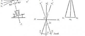
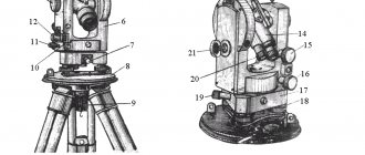
5. The sighting axis of the theodolite telescope must be perpendicular to the axis of its rotation.
The axis of rotation of the theodolite is brought to a vertical position and the central point of intersection of the grid of telescope threads is aimed at a distant, clearly visible object. Then they take a reading along a horizontal circle (for example, with a circle to the right P^, move the telescope through the zenith and again point the intersection of the grid threads at the same object, take a reading along a horizontal circle (with a circle to the left L^ and calculate their difference: Px - JIX The resulting difference in readings Ax-P may contain an error caused not only by the influence of non-compliance with the verified condition, i.e., collimation error C, but also by the eccentricity of the alidade, the value of which in individual specimens of theodolites can reach + G. In order to eliminate the influence of the horizontal eccentricity circle in theodolites with one-sided reading, take a reading along a horizontal circle, for example L2. Unfasten the tripod screw, rotate the theodolite in the tripod 180°, bring the vertical axis of rotation of the theodolite to a vertical position. Point again at the same object, take reading P2 and calculate the difference L2 —P2.
To correct, you should set the reading L - S or P + S in a horizontal circle. Then unscrew the cap covering the screws and the mesh screws, and with a pin, with the vertical corrective mesh screws slightly loosened, move the frame with the side correction screws until the intersection of the center of the mesh with the image is aligned observed object. Elimination of collimation error is achieved in several steps.
6. The vertical thread of the mesh (or bisector) must be perpendicular to the axis of rotation of the pipe (lie in the collimation plane of the pipe).
Fix the theodolite on a tripod and carefully bring its vertical axis to a vertical position using a verified cylindrical level on the alidade of a horizontal circle. Select a clearly visible point k (for example, on a wall), rotating the alidade of the horizontal circle with a guiding screw, and see if the image of point k leaves the middle horizontal thread of the grid. If the image of point k deviates from the horizontal thread of the grid by more than three stroke thicknesses for theodolites T5,$2T5, T5K, 2T5K and by a third of a bisector for theodolite ;T 15 (if it moves in the middle between the bisector strokes), then the grid is installed correctly . Otherwise, you should unscrew the cap covering the corrective screws of the reticle, slightly loosen the screws that fasten the eyepiece part to the tube body, and rotate the eyepiece part so that when the alidade of the horizontal circle is rotated, the image of point k does not leave the horizontal thread of the reticle. After installing the thread mesh, close the screws and screw on the cap.
7. The axis of rotation of the telescope must be perpendicular to the vertical axis of rotation of the theodolite.
The main axis of rotation of the theodolite is brought to a vertical position and, having secured the limb, the center of intersection of the grid of threads is directed to point k (for example, on a wall), located 20-30 m from the theodolite at an angle of 30-50° to the horizon, and the alidade is secured. After this, lower the theodolite telescope to approximately its horizontal position and mark on the wall the projection of the central point of intersection of the grid of threads ax. Rotate the alidade by 180°, move the pipe through the zenith and again point the intersection of the central point of the threads at the same point k, then lower the pipe to the same position as in the first case, and mark on the wall the projection of the intersection point of the grid of threads a2. If the points ax and a marked on the wall do not extend beyond the bisector of the threads, then such an inclination of the axis of rotation of the theodolite tube is acceptable. Elimination of non-compliance with the verified condition is carried out only in the workshop.
8. The zero point of the vertical circle should be close to zero.
Place the theodolite in working position. By crossing the central point of the grid of threads of the theodolite telescope, one points at some clearly visible point k, 150-200 m distant, and brings the level bubble on the alidade of the vertical circle to the zero point in theodolites T15, T5 and 2T5. In theodolites T15K, T5 and T5K there is no level with a vertical circle; its role is played by a self-aligning optical compensator system. Take a reading in a vertical circle. The pipe is moved through the zenith and the intersection of the grid of threads is again directed at the central point, the same point k, and before counting along the vertical circle, the level bubble is brought to the zero point when alidating the vertical circle.
The place of zero (MO) is calculated using the formulas:
for theodolites T15, T5 and T5K
(3.2)
where P is the reading in a vertical circle with the circle to the right; J1 - counting in a vertical circle when the circle is to the left;
for theodolites T15K, 2T5 and 2T5K, microscope scales of vertical circles of which have double digitization
(3.3)
If the MO differs from zero by more than double the accuracy of the optical micrometer, it is corrected as follows.
In theodolites T15, T5, 2T5, a level bubble is installed with a vertical circle at the zero point and a reading is made along the vertical circle. Then, using the leveling screw, reduce the reading P-MO or MO-L + 180° by the value of the zero point (add 360° if necessary) and set the index of the reading device to this reading on the vertical circle, and use the adjusting screws for the level of the vertical circle to bring the bubble to zero -point and repeat the verification again. The verification is repeated in this way until the MO is equal to or close to 0°.
In theodolites T5K, 2T5K, bringing MO to 0° or close to it is carried out only in the workshop.
9. One division of a horizontal or vertical circle should be equal to the length of the scale of the reference microscope.
Combine any stroke of a horizontal or vertical circle with the zero stroke of the microscope scale. The countdown is taken from the next stroke of the circle. The difference between the calculated and its nominal value is called re and about m. The value of ren is determined by at least 12 combinations in different sections of each circle.
To correct the horizontal circle microscope theodolite, you must first remove the side cover of the illumination and slightly loosen the screws of the lower block. And then, by moving these screws, and with them the frame with lenses, along the axis, change the magnification of the microscope, i.e., achieve alignment of the strokes of the horizontal circle with the strokes of the microscope scale. The correction begins by moving the upper lens, which will disrupt the sharpness of the image and cause parallax to appear. Then, by moving the lower lens, the sharpness of the image of the strokes is established without parallax noticeable to the eye. Once installation is complete, tighten the screws and check the ren again.
Correction of the vertical circle is carried out similarly to that described for the horizontal circle by moving the objective lenses secured with the screws of the upper block.
10. The theodolite compensator must provide a constant reading in a vertical circle when the vertical axis of the device is tilted within the limits specified in its passport.
To check this condition, select a sighting target and install the theodolite on a tripod so that one of the lifting screws of the tripod is located in the direction of the sighting target. Bring the level bubble at the alidade of the horizontal circle to the zero point and take a reading along the vertical circle at the circle to the right P or the circle to the left L. Then tilt the theodolite with the lifting screw of the tripod in the direction of the sighting target at the angle that limits the range of action of the compensator (determining the amount of tilt by the number of divisions level), check the correct installation of the theodolite using the other two lifting screws, to do this, point the telescope at the same target and take a reading in a vertical circle. The same is done when tilting the theodolite at the same angle in the other direction, i.e. towards the observer.
Readings along a vertical circle obtained when the theodolite is tilted in two opposite directions (with the cylindrical level bubble positioned at the zero point) must be within the accuracy of readings along this circle. In addition, you should make sure that the lateral tilt of the theodolite does not affect the accuracy of measuring vertical angles. To do this, tilt the theodolite at the same angle to the right and left of the observer, point the telescope at the same target and take readings in a vertical circle. The resulting readings must also be within the Circular Reading Accuracy.
11. The sighting axis of the optical plummet, located in the alidate part of the theodolite, must coincide with its vertical axis of rotation.
To perform this verification, the position of the image of a terrain point relative to the center of the grid of threads is observed when the alidade rotates around a vertical axis.
If the image of a terrain point leaves the center of the optical plummet grid, then unscrew two screws and disconnect the optical plummet cover from the side cover of the theodolite.
By slightly loosening the screws that fasten the ocular leg of the optical plummet and moving it in the plane of the side cover, we achieve alignment of the sighting axis of the optical plummet with the vertical axis of rotation of the theodolite.
Again, the position of the terrain point image relative to the center of the grid is observed when the alidade part is rotated. In this case, the image of the terrain point should not move relative to the center of the optical plummet grid.
In theodolites 2T2, 2T5K and 2T5, optical plummets are adjusted only in the workshop.
Rules and frequency of adjustment
After performing the adjustment procedures carried out with the tool in working position, the following criteria must be met:
- the vertical axis of rotation of the geodetic device must be absolutely plumb;
- verticality of the sighting plane;
- horizontal plane of a horizontal circle.
Mandatory scheduled verifications and subsequent adjustments must be performed once every verification interval, the duration of which is established by the state metrological services of the organization that owns theodolites. By default, the verification interval is equal to one calendar year, and can be adjusted by the organization that owns the theodolite, in agreement with the territorial body of the state metrological service.
At any time during operation, especially during active use of the tool, its transportation or long-term storage, it is necessary to carry out periodic checks of its condition and compliance with the performance characteristics declared by the manufacturer.
It is recommended to carry out checks and possible adjustments in the field before starting any construction work, since only in this case will there be complete confidence in the accuracy of the measurements. Specialized adjustments of jewelry precision should be performed exclusively by technical specialists of metrology companies that have a state license to carry out this type of work.
If the theodolite does not meet the conditions of one of the verifications and the adjustment for some reason did not bring the desired result or was impossible, the instrument is considered unusable and taken out of service with a corresponding entry made in the technical passport indicating the place and date of verification.