An indispensable geodetic instrument intended for goniometric measurements is the theodolite. Its widespread use in general construction work to determine the directions of horizontal and vertical angles, as well as their values, is due to its ease of operation.
Theodolite, as an accurate geodetic instrument, is widely used:
- during the construction of multi-storey residential buildings, shopping centers and other infrastructure facilities;
- when installing complex production equipment to avoid distortions and displacements;
- in private construction: when constructing residential buildings, bathhouses and garages, it is important to know the possible slope of the site plane.
What is a theodolite?
Theodolite is a device designed to measure vertical and horizontal angles. Also applicable for determining distances using a filament rangefinder and magnetic azimuths using a compass. Used for geodetic work, construction, topographic surveys, etc.
There are two types of theodolites: optical and electronic. More modern electronic models are able to accurately determine angles, the height of a building, break a rectangle, or check the alignment of a building’s axes. The theodolite is easy to operate, lightweight and affordable. In this article we will tell you how to work with a theodolite to obtain the most accurate result.
Where to buy theodolite
Considering the importance of the tasks that the theodolite is designed to solve, and it must work flawlessly, the choice of device must be approached carefully, trusting only trusted suppliers. In Tver, it can be ordered from the GEOTver company, which specializes in the supply of specialized geodetic and construction equipment.
By contacting our company, you can count on professional advice regarding the choice of device; we will answer all your questions and help with installation and configuration.
Delivery is made to any region of Russia, including Tver and Moscow (for orders over 50 thousand rubles), we will do it free of charge. Our services also include performance testing and repair of geodetic instruments. To the list of news
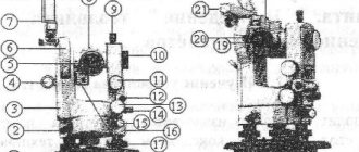
Theodolite device
The main elements that make up a theodolite:
- Dials with degree and minute divisions (horizontal and vertical).
- Alidade is a movable part of the theodolite, to which the dial and sighting system is attached.
- Telescope (sighting device) with fixing and aiming screws.
- Plumb to center over a point. It can be both optical and laser.
- A tribrach (stand) with lifting screws and a round level for leveling the theodolite.
- Microscope for taking readings.
The complete set of theodolite depends on the area in which it will be used. It can be supplemented with a compass guide, rangefinder attachments, sighting markers, etc. In some works, highly specialized theodolites are used: surveying, astronomical, gyroscopic.
How to install a theodolite in working position
Geodesy does not like negligence, and the accuracy of measurements depends on the preparation of the device and its correct installation. Specialists know how to install a theodolite correctly, and the final result depends on the quality of the installation. The device is installed on a tripod, and this must be done at the first stage with the screws loosened. Next, the device is centered, leveled and focused.
Centering
At this stage, it is important that the tripod is installed above the central zone of the device, for which it is centered. To do this, the tripod is installed approximately above the central point, after which a standard plumb line is hung on a special hook. “Rough” centering with an accuracy of 3-5 cm is performed using tripod legs. You can position the device exactly in the center with minimal deviation using a screw.
Leveling
To obtain accurate readings, it is also important that the horizontal circle is in the same horizontal plane. This is achieved by leveling. The device is turned in different directions, and the water bubble serves as a guide. Its deviation from the center by more than 1 unit is not allowed.
Focusing
Each person’s vision has its own characteristics, so the device must be further adjusted by focusing. To do this, you need to rotate the optical ring of the eyepiece until the desired image sharpness is obtained. It is also necessary to focus the scale of the reading mechanism to obtain the necessary clarity on the instrument scale. This can be achieved by rotating the diopter rings of the microscope.
Step-by-step instructions on how to use a theodolite
- 1 step. When working with geodetic equipment, it is worth considering that in order to obtain accurate measurement results, it is necessary to carry out regular checks and adjustments of the theodolite. In addition, it is necessary to periodically monitor the geometric parameters, since the results of the work of a surveyor or builder sometimes do not tolerate errors even of a few arc seconds.
- Step 2. Once the equipment has been checked, you can begin working with the theodolite. First, you need to fix the device above a point with known coordinates, using a tripod and a plumb line or a plumb line. Taking it as a reference point, use levels and guide screws to center the device. The result should be an absolutely horizontal position of the device, as well as the location of the theodolite strictly above the point.
- Step 3. Using the sighting device, you must first aim at the target, and use the screws to align the reticle with the target as accurately as possible. This way the center of the measured object is determined. These actions are performed using a spotting scope, but if there is insufficient light, you can additionally use a special backlit mirror. After completing this procedure, measurements of the vertical and horizontal angles are taken using a theodolite microscope.
- Step 4 To obtain high reliability of measurement results, it is recommended to repeat measurements with a theodolite several times (techniques). Based on the results of repeated measurements, the average values of vertical and horizontal angles are determined.
Working with theodolite
72
Working with a theodolite is the topic of this instruction. Below is a step-by-step method for measuring with a theodolite, the careful implementation of which will ensure accurate results. These instructions assume that the user has basic knowledge of how to work with a theodolite and is familiar with the main components and operating principle of the device.
Installing the theodolite into working position
Measuring horizontal angles with a theodolite involves installing the device at the apex of the angle being determined. To do this, first place a tripod so that the center of the tripod installation site is approximately above the point, and the plane of the site is horizontal. Only after this the theodolite is fixed on a tripod, the device is centered and leveled.
Centering the theodolite is the projection of the axis of rotation of the alidade and limb along a plumb line onto the top of the determined angle with an accuracy of ± 5 mm for a mechanical plumb line, ± 1-2 mm for an optical plumb line. First, the tripod is centered using a mechanical plumb line with an accuracy of 10-15 mm. In this case, it is necessary to install the tripod horizontally so that adjusting the lifting screws allows you to level the device. When installing the device on a tripod, we perform final centering of the theodolite, move the optical theodolite by loosening the mounting screw.
Leveling a theodolite is the sequential leveling of the limb plane of a horizontal goniometric circle (HUC) and bringing the vertical axis of rotation to a plumb position. The leveling process is controlled by the cylindrical level of the GUK alidade and is carried out using theodolite lifting screws. By turning the alidade, guide the level axis along two lifting screws and move the level bubble to the center. Then you should rotate the alidade 90° and, using the third lifting screw, move the bubble back to the center. The steps must be repeated until the bubble moves away from the middle at all positions of the alidade of the horizontal circle. Its permissible deviation is no more than two divisions of the cylindrical level scale.
Leveling theodolite
To obtain a reliable result, working with a theodolite requires compliance with two geometric conditions:
- the axis of rotation of the device is in a vertical position;
- the axis of the cylindrical level is in a horizontal position.
Measuring a horizontal angle with a theodolite
Sighting – aligning the center of the thread grid with a point.
A filament grid is a glass plate with lines printed on it (the nature of their application may vary). The intersection of the midlines is called the center of the Z grid.
Pointing the center of the threads to a point
To sight a theodolite to a point you must:
- Secure the dial.
- Unfasten the alidade in order to use the rough sighting device located at the top of the telescope to set the device approximately at the desired point.
- Secure the alidade.
- For observation, install the telescope so that the grid of threads has a sharp image. This operation is called eye alignment and is performed by rotating the ocular knee.
- Position the telescope so that the point of sight is best visible. This operation is called installation on an object and is performed by rotating the ratchet.
- Aim the center of the reticle exactly at the point of sight using the alidade aiming screws and the telescope. If the vertical circle is on the right side of the tube, when viewed from the eyepiece, they say “circle right” (CR). If the vertical circle is to the left - “circle left” (CL).
Measuring the horizontal angle β
Measuring a horizontal angle with a theodolite involves installing the device at the top of the horizontal angle being measured (the so-called station), and the staff at stations n+1 and n–1.
The crosshairs of the grid of threads are aligned with the lowest visible point of the rail so that the vertical thread coincides with the axis of the rail.
Then perform the following sequence of actions (first half move):
- point the center of the grid of threads at the top of the rear (right) corner (n – 1) and take a count along the limb of the horizontal circle - count a1;
- point at the top of the front (left) corner (n + 1) take the reading a2;
- determine the value of the angle in a circle to the left βcl = a1-a2.
Measurement of the horizontal angle at station n: β – horizontal angle
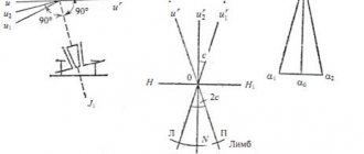
Before the start of the second half-reception (SP), the telescope is unlocked and moved through the zenith position. Then the alidade is unlocked and the device is rotated 180°, measurements are taken at CP. During the second half-measurement (CP), sighting and measurements are carried out similarly; the differences in angle values in the two half-measures (C) should not exceed the double accuracy of the device (t): C < 2t.
Measurement of the horizontal angle β at station n (CL): n – station n–1 – apex of the rear angle n+1 – apex of the front angle a1 – reference to the apex of the rear angle a2 – reference to the apex of the front angle
Calculation of horizontal angles
If the condition of discrepancy in the angle values obtained in two half-steps is met, the average horizontal angle is calculated using the formula: βav = (βCL + βCP) /2.
The limb of the horizontal goniometric circle is always digitized from zero to 360? through 1?, from left to right.
The horizontal circle is measured as follows:
- read the number of degrees of the reference stroke on the alidade scale (according to the figure - 125°);
- minutes are read from left to right from zero, taking into account that the division value on the GI scale is 5´ (according to the figure - 07´).
Theodolite reading microscope RGK TO-15: reading according to the GUK – “125°07´” reading according to the VUC – “-0°35´”
Measuring a vertical angle with a theodolite
The measured tilt angle can be either positive or negative, ranging from -90° to 90°.
Working with a theodolite requires leveling the alidade every time you take a reading. The position is considered horizontal when the bubble of the cylindrical level of the alidade or pipe is located in the middle of the ampoule. However, even when the bubble is in the center of the ampoule, the line of zeros of the reading device may be at a small angle with respect to the horizon line, which is called the zero point of the vertical circle (M0). An important feature of measuring vertical angles is the need to take into account the zero point of the vertical circle. To do this, when creating a survey justification, readings are taken along a vertical goniometric circle (VUC) at CL and CP, and when tacheometric surveying, the zero location is determined at each station before starting work.
When measuring vertical angles with a theodolite, the center of the grid of threads is transferred to the height of the instrument previously marked on the staff. The height of the instrument is determined using a sheet of white paper and a rod, placing it almost close to the eyepiece. The user must observe through the lens. The sheet is moved along the rail until it covers exactly ½ of the field of view. It is convenient to mark the height of the tool on the rail with a thin rubber band.
First, take a reading, sighting to the left while circling. Then, having moved the pipe through the zenith, they sight and take a reading at the right circle.
There are several ways to digitize the limb of a vertical goniometric circle (VUC). The theodolite RGK TO-15 (TO-05) has sector digitization, in which the VUK is divided into 4 sectors of 90°, of which two sectors have positive digitization, and the other two have negative digitization. To take a count:
- read the number of degrees of the reference stroke (according to the figure - “-0°”);
- minutes are read - if there is “-0” at the top - on a negative scale from zero to the reference line, if at the top there is “+0” - on a positive scale from zero to the reference line (according to the figure - “-35?”).
Next, the vertical angle is calculated. In this case, readings from 0° to 90° correspond to the measured positive vertical angle.
Calculation of vertical angles
After taking the readings, the vertical angle is calculated through M0, or based on the results of two readings obtained when sighting the target in two positions of the telescope (CL and CP).
Calculation formulas for sector digitization of the vertical circle limb from zero in both directions - clockwise and counterclockwise (RGK TO-05 and TO-15):
M0 = (KP + CL)/2; v = MO-KP; ν=KL−M0
When calculating using these formulas, it is not necessary to add 360°.
Measuring distances with a theodolite
In this section we will look at how to work with a theodolite to measure distances. In the grid of threads of the theodolite telescope there are two additional horizontal rangefinder lines located on both sides of the center of the grid of threads at equal distances. The presence of these strokes allows the theodolite to measure the distance D from the device to the staff.
To do this, use the staff to determine the value of the rangefinder interval n in centimeters, multiplying the resulting number by 100, then the resulting value from centimeters is converted to meters (the rangefinder coefficient of the telescope is usually equal to 100), i.e.
D = K*n =100*n
In the case shown in the figure:
- report on the upper rangefinder line – 1747 mm;
- report on the lower rangefinder line - 1856 mm.
The rangefinder interval n is equal to the difference between the reports on the lower and upper rangefinder lines.
n = 1856-1747 = 109 mm = 10.9 cm.
Using the formula, we calculate the distance: D = 100 * 10.9 cm = 1090 cm = 10.9 m
For measuring distances with a theodolite using a thread rangefinder, the relative error is usually from 1/100 to 1/300.
Measuring distance with a theodolite using rangefinder lines
72
Measuring a horizontal angle with a theodolite (+ video)
To measure a horizontal angle with a theodolite, you need to install the theodolite in one of the corners of the triangle. Determine right and left direction. Where the zero will be located on the scale is not important, we can get the angle value as the difference in the readings of two points. Aim at the first point and take a reading. Using one of the methods above to check the value, take the reading a second time and calculate the average value; if the discrepancy is no more than 1 minute, then the measurements were made correctly. We record in a journal (notebook). Next, we aim at the second point, and also take a reference. If the value of the right angle is less than the left, you need to add 360 degrees to it. The difference in readings will be our angle.
Measuring angles with a theodolite - studying the brands of instruments
In this section we want not only to touch upon the types of theodolite, but also its markings, because this is what first catches the eye and causes some confusion when purchasing a device, as well as when becoming familiar with its operation. So, first, let’s figure out what kind of devices the industry has in terms of their operation. There is a mechanical device, optical, laser and electronic. The first type is the cheapest and simplest, but has the lowest accuracy, so it is most likely suitable only for study and not for serious development.