Block diagram and designation on Ohmmeter diagrams
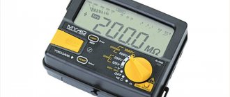
The Ohmmeter measuring device is structurally a dial or digital indicator with a battery or power source connected in series, as shown in the photograph.
All combined instruments - pointer testers and digital multimeters - have the function of measuring resistance.
In practice, a device that measures only resistance is used for special cases, for example, to measure insulation resistance at elevated voltages, ground loop resistance, or as a reference device for testing other low-precision ohmmeters.
On electrical measuring circuits, an ohmmeter is designated by the Greek letter omega enclosed in a circle, as shown in the photograph.
Features of choice
Nowadays there is a wide variety of devices on the market, from inexpensive household models designed for occasional measurements to highly professional testers equipped with specific functions and capabilities. It’s easy to get confused in such a wide variety of devices. The following criteria will help you navigate your choice:
- Range. Maximum and minimum possible resistance readings. Multimeters with advanced functions of megaohmmeters, which are more in demand by professional electricians, stand out.
- Accuracy. The measurement error declared by the manufacturer in a certain temperature range has a great influence on the indicator.
- Scale length. Traditionally, multimeters display 4 digits. More complex devices are equipped with advanced displays.
- Range selection. Automatic detection as an option can be very useful for mass testing of heterogeneous components, but this function increases the cost of the device.
- Temperature coefficient. A parameter that significantly affects the accuracy of measurements. Typically, most instruments are calibrated at an ambient temperature of 20 °C. The resistance of readings to temperature changes significantly affects the price of a multimeter.
- Measurement speed. For domestic needs it is insignificant. Most ohmmeters take approximately one reading per second, but in some cases this may determine the choice.
- Possibility of remote connection. Equipping with data ports significantly speeds up some processes of multiple measurements and measurement processing.
- Durable, moisture-proof and portable. Defines the conditions under which the tester will be operated.
Preparing an Ohmmeter for Measurements
Repair of electrical wiring, electrical and radio engineering products consists of checking the integrity of the wires and searching for contact failure in their connections.
In some cases, the resistance must be equal to infinity, for example, insulation resistance. And in others it is zero, for example, the resistance of wires and their connections. And in some cases it is equal to a certain value, for example, the resistance of the filament of a light bulb or heating element.
Attention! In order to avoid failure of the Ohmmeter, it is allowed to measure the resistance of circuits only when they are completely de-energized.
You must unplug the plug from the socket or remove the batteries from the compartment. If the circuit contains electrolytic capacitors of larger capacity, then they must be discharged by shorting the capacitor terminals through a resistance of about 100 kOhm for a few seconds.
As with voltage measurements, before measuring resistance, it is necessary to prepare the device. To do this, you need to set the device switch to the position corresponding to the minimum measurement of the resistance value.
Before measurements, you should check the functionality of the device, since the batteries may be bad and the Ohmmeter may not work. To do this, you need to connect the ends of the probes together.
The tester's needle should be set exactly to the zero mark; if it is not set, then you can turn the "Set" knob. 0". If this does not work, you need to replace the batteries.
To test the continuity of electrical circuits, for example, when checking an incandescent light bulb, you can use a device whose batteries are dead and the needle does not set to 0, but reacts at least a little when the probes are connected. It will be possible to judge the integrity of the circuit by the fact that the arrow is deflected. Digital devices should also show zero readings, a deviation in tenths of ohms is possible due to the resistance of the probes and the transition resistance in the contacts connecting them to the terminals of the device.
When the ends of the probes are open, the tester arrow should be set to the point indicated on the scale ∞, and in digital instruments, the overload will blink or the number will be displayed 1
on the indicator on the left side.
The ohmmeter is ready for use. If you touch the ends of the probes to the conductor, then if it is intact, the device will show zero resistance, otherwise the readings will not change.
Expensive models of multimeters have a circuit continuity function with audio indication, indicated in the resistance measurement sector with a diode symbol. It is very convenient for testing low-impedance circuits, such as twisted pair cables for the Internet or household electrical wiring. If the wire is intact, then the continuity is accompanied by a sound signal, which eliminates the need to read readings from the multimeter indicator.
Continuity of wires
In the continuity mode, you can check the wires for breaks in any part of the circuit. On the multimeter scale it is indicated by the “sound mixer” icon. If the wiring and contacts are intact, a signal will be heard - a subtle squeaking sound. If there is no conduction, the sound stops.
How to find out if the wires are intact:
- Select the dialing mode with the switch.
- Insert the probes into the COM base and the middle VΩmA connector.
- Touch the contacts of the area under study with a multimeter, closing the circuit.
Based on the presence or absence of sound, conclusions are drawn about the integrity of the wires. It is recommended to pre-ring the probes themselves to prevent damage. They are connected by tips to each other, and a continuous sound should be heard.
Examples from practice of measuring resistance of products
In theory, everything is usually clear, but in practice questions often arise that can best be answered by examples of checking the most common products with an ohmmeter.
Checking incandescent lamps
The incandescent light bulb in a lamp or car on-board devices has stopped shining, how can I find out the reason? The switch, electrical socket or wiring may be faulty. Using the tester, any incandescent lamp from a home lamp or car headlight, filament of fluorescent lamps and energy-saving lamps can be easily checked. To check, just set the device switch to the minimum resistance measurement position and touch the ends of the probes to the terminals of the light bulb base.
The resistance of the light bulb filament was 51 Ohms, which indicates its serviceability. If the thread were broken, the device would show infinite resistance. The resistance of a 220 V halogen light bulb with a power of 50 watts when illuminated is about 968 Ohms, and a 12 volt car light bulb with a power of 100 watts is about 1.44 Ohms.
It is worth noting that the resistance of an incandescent lamp filament in a cold state (when the light bulb is not lit) is several times less than in a warm state. This is due to the physical property of tungsten. Its resistance increases nonlinearly with heating. Therefore, incandescent lamps usually burn out the moment they are turned on.
Unfortunately, LED and energy-saving lamps cannot be checked with a multimeter without disassembling them, since the supply voltage from the base terminals is supplied to the driver diode bridge.
Using an online calculator, you can independently calculate the resistance of any incandescent light bulb or heating element, for example, a heating element, or an electric soldering iron.
| Online calculator for calculating the resistance value based on power consumption | |
| Supply voltage, V: | |
| Power, W: | |
Checking sound-reproducing headphones
It happens with headphones in one of the emitters, or in both at once, the sound is distorted, periodically disappears or is absent. There are two possible options: either the headphones or the device from which the signal is received are faulty. Using an ohmmeter, it is easy to find the cause of their breakdown and repair the headphones.
To check the headphones, you need to connect the ends of the probes to their connector. Typically, headphones are connected to the equipment using a 3.5 mm jack connector, shown in the photo.
One end of the probe touches the common terminal, and the other, in turn, touches the terminals of the right and left channels. The resistance should be the same and be about 40 ohms. Usually, the resistance is indicated in the passport for headphones.
If the resistance of the channels is very different, then there may be a short circuit or a broken wire in the wires. It is easy to verify this; just connect the ends of the probes to the terminals of the right and left channels. The resistance should be twice that of one earphone, that is, already 80 Ohms. In practice, the total resistance of series-connected emitters is measured.
If the resistance changes when the conductors move during measurements, it means that the wire is frayed in some place. Usually the wires fray where they exit the Jack or emitters.
To localize the location of the wire break, during measurements it is necessary to bend the wire locally, fixing the rest of it. Based on the instability of the ohmmeter readings, you will determine the location of the defect. If it’s a Jack, then you need to purchase a detachable connector, bite off the old one with a section of bad wire and solder the wire to the contacts of the new Jack.
If the break is located at the entrance to the headphones, then you need to disassemble them, remove the defective part of the wire, strip the ends and solder them to the same contacts to which the wires were soldered before. In the website article “How to solder with a soldering iron” you can learn about the art of soldering.
Measuring the resistor value (resistance)
Resistors (resistance) are widely used in electrical circuits. Therefore, when repairing electronic devices, it becomes necessary to check the serviceability of the resistor or determine its value.
On electrical diagrams, a resistor is designated as a rectangle, inside which its power is sometimes written in Roman numerals. I – one watt, II – two watts, IV – four watts, V – five watts.
You can check the resistor (resistance) and determine its value using a multimeter turned on in resistance measurement mode. In the resistance measurement mode sector, there are several switch positions. This is done in order to increase the accuracy of the measurement results.
For example, position 200 allows you to measure resistances up to 200 Ohms. 2k – up to 2000 Ohm (up to 2 kOhm). 2M – up to 2,000,000 Ohm. (up to 2 MOhm). The letter k after the numbers denotes the prefix kilo - the need to multiply the number by 1000, M stands for Mega, and the number needs to be multiplied by 1,000,000.
If the switch is set to position 2k, then when measuring a resistor with a nominal value of 300 kOhm, the device will show an overload. It is necessary to switch it to position 2M. In contrast to measuring voltage, it does not matter what position the switch is in; you can always switch it during the measurement process.
Ohm's law
The pattern between three characteristics - current I, voltage U and resistance R - was established by the German physicist Georg Ohm in 1826. He found out that they are connected by a fairly simple relationship:
I=U/R
Based on the formula and knowing any 2 quantities, it is very easy to find the missing third:
U=I*R
R=U/I
In turn, the resistance depends on the properties of the material and the size of the conductor:
R=ρ*l/s, where ρ is the resistivity per 1 m (tabular value), l is the length, s is the area of the conductor.
Consumers in the circuit (resistors) can be connected in series, that is, without branching. To find the total resistance, all values are added together:
Rtot. = R1 + R2+…
The current strength will be the same in all sections, but the voltage will be different:
With a parallel connection, the dependency is more complex:
1/Rtotal=1/R1+1/R2+…
In this case, the voltage is constant, but the current strength in each section is different.
Often there are mixed circuits where serial and parallel connections of resistors are combined. You can check the parameters of a circuit of any configuration using measuring instruments.
Online calculators for determining resistor values by color coding
Sometimes when checking a resistor, the ohmmeter shows some resistance, but if the resistor, as a result of overloads, has changed its resistance and it no longer corresponds to the marking, then such a resistor should not be used. Modern resistors are marked using colored rings. The most convenient way to determine the value of a resistor marked with colored rings is to use an online calculator.
Online calculator for determining the resistance of resistors marked with 4 colored rings
Online calculator for determining the resistance of resistors marked with 5 colored rings
Instructions
So, how to measure resistance with a multimeter? This requires only three steps, but first you must make sure that the network being tested is completely de-energized.
The black test lead is inserted into the COM socket, after which the red lead is inserted into VΩmA. Then you need to turn on the device. This is most often done by turning the measurement switch. To work with the smallest resistances, you will need to set the switch to the letter “omega” and set the range to 200, that is, within the range of 0.1-200 Ohms (measurement of low resistances). Next, a check is made for the closure of the measuring circuit, for which the probes are closed to each other. If the multimeter is working properly, an indicator of about 0.3-0.7 will appear on the screen and, as already mentioned, it should be constant. This indicator displays the resistance of the test leads themselves. If this indicator is higher or changes frequently, the wires should be updated. If the wires are open, the screen should read one, indicating very high (infinite) resistance.
In order to take a measurement, you must simultaneously touch the contacts of the circuit. If the system is working properly, the multimeter will take a reading. If a power failure test is performed, the tester will display new readings. The resistance in this case should be quite low, down to 1.5 Ohms. If you need to measure the resistance of a current consumer, for example, a light bulb or a transformer winding, the indicator can jump to 150-200 Ohms. There is a rather characteristic feature: as the power of the current consumer increases, checking the resistance of the device with a multimeter shows a lower result.
If the multimeter displays all the same values, move on to a new range and continue trying. There is an important point here. If we set the switch to 2000k and grasp the probe contacts with bare hands, it turns out that we are measuring the body resistance, which, of course, will affect the results.
Checking diodes with a multimeter or tester
Semiconductor diodes are widely used in electrical circuits to convert alternating current to direct current, and usually when repairing products, after an external inspection of the printed circuit board, the diodes are first checked. Diodes are made from germanium, silicon and other semiconductor materials.
In appearance, diodes come in different shapes, transparent and colored, in a metal, glass or plastic case. But they always have two conclusions and immediately catch the eye. The circuits mainly use rectifier diodes, zener diodes and LEDs.
The symbol for diodes in the diagram is an arrow pointing to a straight line segment. A diode is designated by the Latin letters VD, with the exception of LEDs, which are designated by the letters HL. Depending on the purpose of the diodes, additional elements are added to the designation scheme, which is reflected in the drawing above. Since there is more than one diode in a circuit, for convenience, a serial number is added after the letters VD or HL.
It is much easier to check a diode if you understand how it works. And the diode works like a nipple. When you inflate a ball, rubber boat or car tire, air enters it, but the nipple does not allow it back.
A diode works exactly the same. Only it passes in one direction not air, but electric current. Therefore, to check the diode, you need a direct current source, which can be a multimeter or a pointer tester, since they have a battery installed.
Above is a block diagram of the operation of a multimeter or tester in resistance measurement mode. As you can see, a DC voltage of a certain polarity is supplied to the terminals. It is customary to apply the plus to the red terminal, and the minus to the black. When you touch the diode terminals in such a way that the positive output of the device is on the anode terminal of the diode, and the negative output is on the cathode of the diode, then current will flow through the diode. If the probes are swapped, the diode will not pass current.
A diode can usually have three states - good, broken or broken. During a breakdown, the diode turns into a piece of wire; it will pass current no matter the order in which the probes touch. If there is a break, on the contrary, the current will never flow. Rarely, but there is another condition when the transition resistance changes. Such a malfunction can be determined by the readings on the display.
Using the above instructions, you can check rectifier diodes, zener diodes, Schottky diodes and LEDs, both with leads and in SMD version. Let's look at how to test diodes in practice.
First of all, it is necessary, observing the color coding, to insert the probes into the multimeter. Usually a black wire is inserted into COM, and a red wire into V/R/f (this is the positive terminal of the battery). Next, you need to set the operating mode switch to the dialing position (if there is such a measurement function), as in the photo, or to the 2kOm position. Turn on the device, close the ends of the probes and make sure it is working.
We’ll start the practice by checking the ancient germanium diode D7, this specimen is already 53 years old. Germanium-based diodes are now practically not produced due to the high cost of germanium itself and the low maximum operating temperature, only 80-100°C. But these diodes have the smallest voltage drop and noise level. They are highly valued by tube amplifier builders. In direct connection, the voltage drop across a germanium diode is only 0.129 V. The dial tester will show approximately 130 Ohms. When the polarity is changed, the multimeter shows 1, the dial tester will show infinity, which means a very high resistance. This diode is OK.
The procedure for checking silicon diodes is no different from checking those made of germanium. The cathode terminal is usually marked on the diode body; it can be a circle, line or dot. In direct connection, the drop across the diode junction is about 0.5 V. For powerful diodes, the drop voltage is less, and is about 0.4 V. Zener diodes and Schottky diodes are checked in the same way. The voltage drop of Schottky diodes is about 0.2 V.
For high-power LEDs, more than 2 V drops at the direct junction and the device can show 1. But here the LED itself is an indicator of serviceability. If, when turned on directly, you can see even the faintest glow of the LED, then it is working.
It should be noted that some types of high-power LEDs consist of a chain of several LEDs connected in series and this is not noticeable from the outside. Such LEDs sometimes have a voltage drop of up to 30 V, and they can only be tested from a power supply with an output voltage of more than 30 V and a current-limiting resistor connected in series with the LED.
Types of devices for taking measurements
Almost all multifunctional measuring instruments have the ability to measure the impedance value. Based on their operating principle and functionality, manufactured devices can be digital or analog. At the same time, their important characteristics are the error and measurement range.
Before you start working with the tester, you need to make sure that its batteries are in good condition. If a digital type of device displays a blinking battery indicator, this means that the battery needs to be replaced. For a pointer instrument, a signal to replace the power elements will be the inability to set the pointer to the zero position.
To obtain the correct result, it is necessary not only to use the configured device, but also to monitor the ambient temperature. As is known from the laws of physics, when heated, the resistance value of conductors increases, and that of semiconductors decreases. The optimal temperature is considered to be 20 degrees Celsius.
Digital multimeter
The main feature of a digital multimeter is the presence of a screen; the measured value is clearly displayed on it. The operating principle of the device is based on comparing the measured signal with a reference signal; for this, an analog-to-digital converter is used.
To carry out a measurement, the tester is connected with a set of wires to the element being measured. At one end of each wire there is a plug intended for installation in the meter socket, and at the other there is a contact probe. The procedure for measuring the resistance of a resistor with an electronic multimeter can be represented as the following:
- Pressing the ON/OFF button turns on the device.
- The probes are connected to the two ends of the resistor, the reverse ends of the wires to the Ω and COM connectors.
- The switch sets the approximate resistance.
- If a unit is displayed on the indicator, the switch should be moved up one position, i.e., increase the measurement limit.
- If, when taking readings, numbers other than one are displayed on the screen, this will be the resistance value.
In the same way, you can measure the resistance of the pn junction of a semiconductor. A digital device is convenient to measure constant resistance, but it is useless when you need to find out its variable value. For such measurements, it is preferable to use a pointer instrument.
Pointer device
The very first measuring instruments were equipped with a pointer device. This device was an electromechanical head. Structurally, it is made in the form of a frame located in a magnetic field. An electrical signal is supplied to this head through various resistances. Depending on the current strength, the arrow in the frame deviates, settling in a certain position. The range of the needle deflection is calibrated, according to these values and the required value is calculated.
The technical capabilities of an analog tester are largely determined by the sensitivity of the magnetoelectric measuring device. Its main advantage is its inertia and immunity to interference during the measurement of DC voltage and resistance value.
Pointer instruments are ideal for displaying signal dynamics. The tester instantly shows its change. At the same time, such a device has a large error when measuring in high-resistance circuits, and there is some difficulty in interpreting the measurement results.
The device is turned on according to the instructions indicated on the back of the battery cover. The switch button selects the operating mode for a constant, variable value or resistance (respectively “—”, “~”, “Ω”). A double click is used for a measurement pair. The calculation range switch is set to a fixed value corresponding to the expected measurement value.
Before measuring the resistance value, the tester is adjusted by rotating the zero knob until the arrow points to the “∞” value. When choosing the “Ω” measurement range, the resistance values are not marked with the maximum numbers in this range, but have the following form: x1, x10, x100. This means that the resulting value will be measured in Ohms, kOhms, and MOhms. Active resistance is measured from a direct current source (battery) installed in the device.
Having turned on and prepared the tester, you need to attach the probes to the object being tested. According to the arrow readings, the result will appear on the measuring scale, which is then multiplied by the range multiplier.
Using a Megger
A megohmmeter is a specialized measuring device. Before starting measurements, you must strictly adhere to the requirements of the PUE (electrical installation rules). The basic rules include:
- Measurements are taken at the limit of the tester, which exceeds the highest possible resistance value. If such a value is unknown, then they start with the maximum possible limit, which is reduced to the minimum possible to improve the accuracy of the result.
- Before checking the resistance with a tester, you will need to make sure that the object being tested is de-energized.
- All elements with reduced insulation, capacitors, semiconductors are short-circuited before testing begins.
- During the measurements, the test object is grounded.
- After completing measurements, especially for devices with large capacitance (for example, long-distance wires), before disconnecting the probes of the device, it is necessary to remove the residual charge by shorting it to ground.
- Taking readings of the insulation resistance of power and lighting wiring occurs with switches turned off, fuses removed, and lamps removed.
- It is strictly prohibited to measure insulation near high voltage lines or during a thunderstorm.
A megohmmeter is a complex device consisting of a current generator and a measuring head. Also included are: current-limiting resistors, terminal blocks, a dielectric housing and a mode switch.
The device has three terminals for external connection of wires. The ground is connected to one, the line to the other, and the screen to the third. Which wire is connected where is indicated in the instructions for the device.
The ground and line terminals are used for any insulation readings relative to the ground loop, and the shield contact is needed to reduce the influence of leakage currents. Such currents appear when measuring between two wire strands located parallel to each other. The screen contact is connected with a special wire that comes with the device.
We recommend reading: Simple diagrams for beginner radio amateurs
After connecting all the probes on old-style devices, you will need to twist the knob, which will ensure the operation of the internal generator and the supply of voltage to the object being tested. In modern devices, a button is used instead of a handle, and power is taken from installed batteries or galvanic batteries. The generator voltage can range from 100 volts to 2.5 kV. As soon as the voltage is applied, for a pointer instrument, readings are taken from the arrow on the scale corresponding to the selected range, and for a digital type of instrument, readings are taken in the form of numbers on the indicator.
Checking electrolytic capacitors
There are two main types of capacitors, simple and electrolytic. Simple capacitors can be included in the circuit in any way you like, but electrolytic capacitors can only be connected with polarity, otherwise the capacitor will fail.
On electrical diagrams, a capacitor is indicated by two parallel lines. When designating an electrolytic capacitor, its connection polarity must be indicated with a “+” sign.
Electrolytic capacitors have low reliability and are the most common cause of failure of electronic components of products. A swollen capacitor in the power supply of a computer or other device is not a rare sight.
Using a tester or multimeter in resistance measurement mode, you can successfully check the serviceability of electrolytic capacitors, or, as they say, ring. The capacitor must be removed from the printed circuit board and be sure to be discharged so as not to damage the device. To do this, you need to short-circuit its terminals with a metal object, such as tweezers. To test the capacitor, the switch on the device must be set to resistance measurement mode in the range of hundreds of kilo-ohms or mega-ohms.
Next, you need to touch the terminals of the capacitor with the probes. At the moment of contact, the instrument needle should sharply deviate along the scale and slowly return to the position of infinite resistance. The speed at which the needle deflects depends on the capacitance value of the capacitor. The larger the capacitor capacity, the slower the shooter will return to its place. A digital device (multimeter), when touching the probes to the terminals of the capacitor, will first show a small resistance, and then increasingly increasing up to hundreds of megohms.
If the behavior of the devices differs from that described above, for example, the resistance of the capacitor is zero Ohm or infinity, then in the first case there is a breakdown between the windings of the capacitor, and in the second, a break. Such a capacitor is faulty and cannot be used.
A few important rules
In how to measure resistance with a multimeter, consider the following points:
- Do not switch modes during measurements.
- Operate the multimeter with non-conductive gloves.
- Clean the contact area if it is covered with an oxide film.
- Do not take measurements if the humidity in the area being studied is high.
- Do not use the tester if it has mechanical damage or the braiding of the probes/wires is deformed.
- If you want to measure the resistance of an element soldered into the board, you will have to unsolder at least one pin. Otherwise, the measurement result will be distorted (this is due to the fact that there are most likely other conductors on the circuit). If you want to test a part with multiple pins, disconnect it completely from the circuit.
How to measure correctly
To correctly measure the resistance parameters of a wire or cable you need:
- Turn on the multimeter and set it to the appropriate values;
- Connect one probe in any way to one contact of a wire or element, and the other to another free one;
- If one lights up on the display, then the maximum power is not enough and you need to set a higher limit;
- Compare the obtained values with the nominal markings.
Important! During the measurement process, you should adhere to simple but important safety measures: do not touch the exposed parts of the probes with your hands and be careful when measuring the parameters of some types of electrical appliances.
Correct and safe measurement is essential for accurate results
Thus, the electrical network can be determined by many parameters, one of which is resistance. The multimeter way to find out resistance is one of the most common and simplest. This does not require any special knowledge or skills. It is enough to have the subject of analysis and the apparatus to check and record the relevant data.
Verification procedure
Analog devices must be verified in accordance with GOST 8.409. The same applies to resistance meters that are part of combined instruments. Information on methods, operations and means of verification is set out in GOST 8.336. If the device includes additional parts and probes, they are also subject to verification. In the list of verification activities for all types of devices:
- Visual inspection. It allows you to check the completeness and compliance of the markings, as well as detect external defects that affect the performance of the device;
- Testing;
- Determination of the main error. To do this, a series of measurements is carried out, in which a multi-valued resistance measure or a set of measuring coils is used.
During the initial verification, it is necessary to test the insulation strength using a special installation and measure its resistance with a megohmmeter. For digital models, the protective grounding resistance is additionally checked. During the initial verification of the resistance meter, it is necessary to determine the operating voltage that the built-in source produces. You should also check the time for setting the readings, the tilt of the device and calculate the variant values.
An ohmmeter
is a useful and in many cases irreplaceable device. Sometimes it is used for other purposes than for standard measurements. For example, you can use an ohmmeter to check other measuring instruments, surface resistance, etc. An ohmmeter is suitable for many applications.