Despite the fact that the megohmmeter is considered a professional measuring device, in some cases it can also be in demand at home. For example, when you need to check the condition of electrical wiring. Using a multimeter for this purpose will not allow you to obtain the necessary data; at most, it can detect the problem, but not determine its scale. That is why measuring insulation resistance with a megohmmeter remains the most effective test method; this is described in detail in our article.
Types of testers
When operating electrical devices, digital megohmmeters of the model: F4101/4102 from 100.0 to 1000.0 V are widely used. Installers still work with tester brands M4100/1, 4100/5 and MS-05 m from 100.0 to 2500.0 V. The choice of megger size is based on rated resistance of the device under test: power cables and transformers, machines and insulators.
To determine the insulation condition in electrical installations up to 1000.0 V, it is allowed to use megohmmeters from 100.0-1000.0 V, and in installations over 1000.0 V - 1000.0-2500.0 V. Devices are also classified according to the generated voltage and resistance limits in MOhm:
- 500.0 V - 500.0;
- 1000.0 V - 1000.0;
- 2500.0 V - 2500.0.
Additional Information. The devices also differ in accuracy classes. The popular M4100 model has an error of no more than 1%, and the F4101 brand has an error of up to 2.5%. The selection of electrical installation testing devices is carried out taking into account acceptable performance indicators.
Electronic meter
Electronic meter
A digital or electronic tester is a modern type of equipment, equipped with a powerful generator with field-effect transistors. Measurements are made by comparing the voltage drop in a reference circuit with a fixed resistance. The results are shown on the panel. The test results saving function accumulates data for subsequent analysis. This model differs from analog devices in its compact size and light weight. Advantages of a digital tester:
- High level of accuracy, allows you to determine resistance over large sections of the circuit;
- convenient, easy-to-read digital panel;
- technological accessibility for measurement by one user;
- works great even in very busy spaces;
- convenient and safe to use.
Disadvantages of the electronic type megger:
- Requires external power source;
- high prices for products.
Electromechanical meter
Electromechanical device
These models have an analog display on the front panel of the tester and a hand crank used to rotate and generate voltage that passes through the electrical system.
Advantages of a manual megger:
- Remains important in today's high-tech world, remaining the oldest method for determining resistance values.
- No external source is required for operation.
- Low prices on the market.
Disadvantages of a manual megger:
- At least 2 people are required for operation, one to rotate the handle, the other to connect the megger to the electrical system being tested.
- Low measurement accuracy.
- Requires a large free space for placement.
- Provides an analog measurement result.
- High requirements for safety during use.
Circuit design features:
- Deflector and Control Coil - Connected in parallel with the generator, mounted at right angles to each other and maintained in polarity so as to produce torque in the opposite direction.
- Permanent magnets create a magnetic field to deflect the pointer using a North-South magnetic pole.
- Pointer - one end connected to the coil, the other deviates on a scale from infinity to “0”.
- A scale is provided at the top of the megger from the zero to infinity range and allows the user to read the value.
- Connecting a direct current (DC) source or battery.
- The test mode is generated by a generator for a manually controlled megger. A battery or electronic charger is provided for the digital megger for the same purpose.
Note! Current coil resistance helps protect the tester from any damage during testing due to low external electrical resistance
Purpose of measurements taken
The technical data sheet contains information about the insulation resistance of wires and cables. Therefore, with its regular monitoring, it is possible to detect changes occurring with it under existing operating conditions. The data obtained from the monitoring results makes it possible to prevent such events as electric shock upon contact with a wire or cable, overheating or ignition of a wire or cable.
If monitoring requires certain time and money, then the consequences of accidents from fires or electric shocks are much more noticeable
Therefore, it is important to promptly identify those areas with wires or cables that are already in a condition that requires their replacement due to wear of the insulating layer. And this replacement must be done before problems associated with it appear.
In electrical networks, especially with voltages of more than 1000 Volts, a lot of electrical equipment is used, which uses oil and other materials with very powerful combustion. For example, a distribution substation where the insulation ignites in one location can quickly become one large fire. This means that the fire safety of the entire substation is related to the condition of the insulating layer of wires and cables laid in it.
Data from the results of monitoring their isolation are subject to recording in special protocols. They are compiled in the course of performing the necessary measurements by measurement laboratories and only in this case can they be presented to the relevant state regulatory authorities performing fire safety inspections of objects. Protocols drawn up in a different way have no legal force.
Design and principle of operation of a megohmmeter
Checking the cable insulation resistance with a megohmmeter
The aging of electrical wiring insulation, like any electrical circuit, cannot be determined with a multimeter. Actually, even with a rated voltage of 0.4 kV on the power cable, the leakage current through microcracks in the insulating layer will not be so large that it can be detected by standard means. Not to mention measuring the resistance of intact cable insulation.
In such cases, special devices are used - megohmmeters, which measure the insulation resistance between the motor windings, cable cores, etc. The principle of operation is that a certain voltage level is applied to the object and the rated current is measured. Based on these two values, the resistance is calculated according to Ohm's law (I = U/R and R=U/I).
It is typical that megohmmeters use direct current for testing. This is due to the capacitance of the measured objects, which will pass alternating current and thereby introduce inaccuracies in the measurements.
Structurally, megaohmmeter models are usually divided into two types:
- Analog (electromechanical) - old-style megohmmeters. Analogue megohmmeter
- Digital (electronic) – modern measuring devices. Electronic megohmmeter
Let's consider their features.
Electromechanical megohmmeter
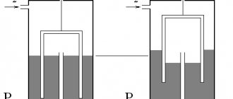
Let's consider a simplified electrical circuit of a megohmmeter and its main elements
Simplified diagram of an electromechanical megohmmeter
Designations:
- A manual DC generator, a dynamo is used as such. As a rule, to obtain a given voltage, the rotation speed of the hand generator handle should be about two revolutions per second.
- Analog ammeter.
- An ammeter scale calibrated to indicate resistance measured in kiloohms (kOhm) and megaohm (MOhm). The calibration is based on Ohm's law.
- Resistance.
- KOhm/Mohm measurement switch.
- Clamps (output terminals) for connecting test leads. Where “Z” is the ground, “L” is the line, “E” is the screen. The latter is used when it is necessary to check the resistance against the cable shield.
The main advantage of this design is its autonomy; thanks to the use of a dynamo, the device does not require an internal or external power source. Unfortunately, this design has many weaknesses, namely:
To display accurate data for analog instruments, it is important to minimize the mechanical impact factor, that is, the megohmmeter must remain stationary. And this is difficult to achieve by rotating the generator handle. The displayed data is affected by the rotational uniformity of the dynamo. Often the measurement process requires the efforts of two people
Moreover, one of them performs purely physical work - he rotates the handle of the generator. The main disadvantage of the analog scale is its nonlinearity, which also negatively affects the measurement error.
Note that in later analog megohmmeters, manufacturers abandoned the use of a dynamo, replacing it with the ability to operate from a built-in or external power source. This made it possible to get rid of characteristic shortcomings; in addition, the functionality of such devices has significantly increased, in particular, the voltage calibration range has expanded.
Modern analog model of megaohmmeter F4102
As for the principle of operation, it has remained unchanged in analog models and consists of a special gradation of the scale.
Electronic megohmmeter
The main difference between digital megohmmeters is the use of a modern microprocessor base, which can significantly expand the functionality of the devices. To obtain measurements, just set the initial parameters and then select the diagnostic mode. The result will be displayed on the information board. Since the microprocessor makes calculations based on operational data, the accuracy class of such devices is significantly higher than that of analog megohmmeters.
Separately, mention should be made of the compactness of digital megohmmeters and their versatility, for example, testing residual current devices, measuring ground resistance, phase/zero loops, etc. Thanks to this, comprehensive tests and all necessary measurements can be carried out with one device.
How to measure cable insulation resistance
Most often it is necessary to measure the insulation resistance of cables. How to use a megohmmeter in this case? If the cable is already in use, it is disconnected from the power supply and the load connected to it is removed. There are several types of changes:
- Each cable core in relation to all the others, united in a bundle and connected there with an earth wire.
This is how the cable insulation condition is measured
- Each core is relative to the ground (the remaining wires are not grounded).
- Each core is relative to all other conductors (each pair of wires).
Points 2 and 3 are performed if the results of the first measurement are below normal. These measurements are simple, but if you have lived a lot, they take a lot of time. It’s good that electricians mainly use three-core wires, and only when supplying a three-phase network can there be more of them.
How to use a megohmmeter: this is how you measure the insulation resistance between two wires in a cable
When measuring on the panel, all machines are switched to the “off” position, the load is removed, and then measurements are taken. In this case, you don’t have to remove the wires from the sockets, but touch the contact screws with probes. Be careful: the input line on the input machine (connected to the upper sockets) cannot be measured without turning off the power at the substation.
If the cable is shielded (there is a metal braid of wire, steel or aluminum tapes), install a probe with a forked tip, and the screen is added to the bundle to the wires and the “ground”.
Purpose and principle of operation
Topic: “measuring angles with a theodolite and determining distances using a rangefinder”
A megohmmeter is a measuring device designed to measure the insulation resistance of wires and other live parts and circuit elements. Its sensitivity is sufficient to indicate in which part of the line the insulation of the wires (or terminals) has become so old that it can break through under the influence of high voltage. An insulation breakdown in high-voltage networks and electrical circuits is a source of step voltage, the current of which flows into the ground, and a possible fire.
In addition to the measuring head and power supply, the megohmmeter includes a range switch for the resistance being measured and additional resistors, which set this limit. To connect the device, you need terminals through which it is connected to the circuit or line being measured using probes with wires insulated from each other. To ensure reliable connection, the ends of the probes connected to the circuit being measured are equipped with “crocodiles” that vaguely resemble a clothespin. The use of a crocodile makes it possible to establish reliable electrical contact. For power supply, without which the resistance of the medium being measured cannot be measured, either a separate AC adapter or a battery or accumulator is used. It, in turn, produces a voltage that is taken into account in the calculation of resistance.
Unlike (kilo) ohmmeters, where the voltage supplied to the circuit being measured does not exceed one or several volts, this value in megohmmeters is set in the range of 50-5000 V, which forces measurers to use dielectric gloves, a rubber carpet and shoes with the same sole, and securely insulated instrument. The principle of operation of the megohmmeter, like its brother - the ohmmeter, is based on the application of Ohm's law, which guides all electricians and power engineers. According to this law, knowing the voltage (or EMF of the power source) and measuring the leakage current, it is possible to determine the current resistance of the medium through which this current passes. Before measurements are taken, the section of the line or circuit on which the resistance is measured is disconnected from the general circuit.
Based on the measurement results, the effective value of the electrical strength is calculated (in volts per meter of insulator thickness, but a multiple unit is used - kilovolts per millimeter of dielectric layer). There is an approximate standard for the minimum number of megaohms into which any of the electrical insulators tested for “breakdown” must fit. For example, the material of the kinescope board - textolite, in now outdated televisions did not have a volumetric resistance of less than 100 megaohms per millimeter of thickness (between the printed tracks), since a voltage of 4 to 25 kilovolts was applied to the kinescope electrodes.
The leakage current must be such that it can be neglected, that is, an order of magnitude less than its operating value. However, GOST 183-74 does not dictate clearer values for the volumetric and surface resistance of a dielectric - specific requirements for it are calculated by design engineers at the stage of system and circuit design of a particular device. If the total resistance of the tested section of the line or circuit is less than this value, the insulator must be replaced before the current leakage becomes noticeable or leads to breakdown of the insulator and a short circuit.
Safety in measurements
Measurements with a megohmmeter always tell insulated conductors the charges, and the better the quality of the insulation, the longer the charge lasts. For safety reasons, be sure to remove these charges using wires with insulated handles. The connection points of the wires from the device are short-circuited and each of the conductors is additionally shorted to ground. There is only one goal - to remove all residual charges for the safety of people.
Measuring the insulation of electrical installations is easier than measuring lines and networks due to the concentration and proximity to personnel. Below is a step-by-step procedure for taking measurements on lines.
Review of manufacturers
The leading manufacturers of exclusively megaohmmeters are the following: Megeon, Fluke, Aktakom, Radio-Service. Soviet-made devices of the ES type are mainly pointer devices, few of them are produced in Russia. Subsequently, they were replaced by Russian digital meters - digital meters. Soviet electrical measuring equipment for the most part did not need a trademark, of which there are dozens now - it was produced en masse at instrument-making factories owned by the USSR. Today, pointer ohmmeters are also produced - but they are a niche offering. The instrumentation market is mainly occupied by digital electrical meters with advanced functionality that brings them closer to multimeters.
User manual
The insulation resistance is checked on de-energized equipment or cable lines or electrical wiring. Remember that the device generates high voltage and if the safety precautions for using a megohmmeter are violated, electrical injuries are possible, because Measuring the insulation of a capacitor or long cable line can cause a dangerous charge to accumulate. Therefore, the test is carried out by a team of two people who have an understanding of the dangers of electric current and have received safety clearance. During testing of the object, no unauthorized persons should be nearby. Remember about high voltage.
Each time the device is used, it is inspected for integrity, for the absence of chips and damaged insulation on the measuring probes. Trial testing is carried out by testing with open and closed probes. If tests are carried out with a mechanical device, then it must be placed on a horizontal, flat surface so that there is no error in the measurements. When measuring insulation resistance with an old-style megohmmeter, you need to rotate the generator handle at a constant frequency, approximately 120-140 rpm.
If you measure resistance relative to the body or ground, two probes are used. When testing the cable cores relative to each other, you need to use the “E” terminal of the megohmmeter and the cable screen to compensate for leakage currents.
Insulation resistance does not have a constant value and largely depends on external factors, so it can vary during measurement. The check is carried out for at least 60 seconds, starting from 15 seconds the readings are recorded.
For household networks, tests are carried out with a voltage of 500 volts. Industrial networks and devices are tested with voltages in the range of 1000-2000 volts. You need to find out exactly what measurement limit to use in the operating instructions. The minimum permissible resistance value for networks up to 1000 volts is 0.5 MOhm. For industrial devices, no less than 1 MOhm.
As for the measurement technology itself, you need to use a megohmmeter according to the method described below. As an example, we took the situation with measuring insulation in a switchboard (power panel). So, the procedure is as follows:
We remove people from the part of the electrical installation being tested. We warn about the danger and post warning posters. We remove the voltage, completely de-energize the shield and input cable, and take measures against erroneous voltage supply. We hang up a poster - DO NOT TURN ON, PEOPLE ARE WORKING. We check that there is no voltage. Having previously grounded the terminals of the test object, we install the measuring probes, as shown in the megohmmeter connection diagram, and also remove the grounding. This procedure is carried out with each new measurement, since nearby elements can accumulate a charge, introduce an error in the readings and pose a danger to life. Installation and removal of probes is carried out using insulated handles while wearing rubber gloves.
Please note that the insulating layer of the cable must be cleaned of dust and dirt before checking the resistance. We check the insulation of the input cable between phases A-B, B-C, C-A, A-PEN, B-PEN, C-PEN. The results are recorded in the measurement protocol. We turn off all automatic devices, RCDs, turn off lamps and lighting fixtures, disconnect the neutral wires from the neutral terminal. We measure each line between phase and N, phase and PE, N and PE
The results are entered into the measurement protocol. If a defect is detected, we disassemble the measured part into its component elements, look for the fault and fix it.
At the end of the test, we use portable grounding to remove the residual charge from the object, by short-circuiting, and from the measuring device itself, discharging the probes among themselves. According to these instructions, you need to use a megohmmeter when measuring the insulation resistance of cable and other lines. To make the information more clear to you, below we have provided videos that clearly demonstrate the order of measurements when working with certain models of devices.
Basic rules for the safe use of a megohmmeter
Verification and testing
Any work in electrical installations may only be carried out with working electrical devices. In relation to a megohmmeter, this means that it must simultaneously meet two requirements and be:
Testing means testing the resistance of its own insulation and all components in an electrical testing laboratory with increased voltage. Based on its implementation, the owner of the device is issued a certificate authorizing the operation of the megohmmeter for a certain, limited period. Verification is carried out by metrology laboratory specialists in order to determine the accuracy class of the device and apply a stamp on its body indicating that it has passed control measurements. The owner is obliged to take measures to ensure the safety of the applied stamp with the date and number of the verifier. If it disappears, the device is automatically considered faulty.
Types of jobs
The megohmmeter is selected for each measurement primarily based on the output voltage. It can perform two different types of checks:
The first method involves creating an extreme case for the test area. For this purpose, it is supplied not with the rated voltage, but with an overestimated voltage provided for in the technical documentation. The test time is also chosen to be quite long. This allows you to timely identify all insulation defects and eliminate their manifestation during operation.
The second method uses a more gentle mode. The voltage for it is selected to a lower value, and the measurement time is determined by the duration of the end of the capacitive charge of the measuring section. For electrodynamic devices, it does not exceed a minute (that’s how long you need to turn the knob at a speed of 120÷140 rpm), and for electronic devices - about 30 seconds (keep the button pressed).
For example, measuring the insulation resistance of a particular electrical circuit must be done with a megohmmeter that produces 500 volts at the output. Then to test it you will need a 1000 V device.
Insulation measurements are carried out by electrical personnel of various professions, and the testing function is provided only to specialists from the insulation service laboratory. Quite often, the capabilities of a megohmmeter for these purposes are not enough for them, and they include in their work additional installations and sources of extraneous voltage that have higher powers and measuring capabilities.
Knowledge of the features of the circuit being tested
Before applying high voltage to the area being measured, it is necessary to take measures to prevent breakdowns and malfunctions of its components. Modern electrical equipment uses many semiconductor elements, various capacitors, measuring and microprocessor devices. They are not designed for the operating conditions created by the megohmmeter generator voltage. All such devices must be protected. To do this, they are removed from the circuit or shunted in a certain way. After the measurements are completed, the entire circuit must be restored and brought into working condition.
Why do you need to test transformers?
The power transformer is an important transmission unit as part of a powerful and complex power system that provides power to a significant number of industrial and household energy consumers. Such a unit must be reliable and serviceable for a long time, so that there is no failure in the useful work of industrial consumers, and there is no shortage of electricity consumption in the everyday life of ordinary people.
That is why oil and dry power voltage converters are constantly tested:
- At manufacturing plants, numerous inspections and performance tests are carried out - in order to guarantee that a complex technical device for converting voltage from one class to another after manufacturing is fully operational and ready for further work at the site;
- When installing a supply system in an ensemble, testing according to a special acceptance testing methodology - in order to understand that during the transportation and subsequent installation of power equipment, no defects or installation errors occurred or were created that would not be able to provide proper, stable power to the required number of consumers;
- Periodically during the operation of electrical installations and components, as a result of which certain failures or defects of complex transmission equipment may also occur - to prevent pre-emergency or emergency conditions. To identify defects at early stages and timely eliminate them in operational mode with minimal losses for all energy consumers.
Such monitoring and checks of the operation of power transmission devices ensure maximum quality of operation of power systems as a whole, which means that the maximum quantity and quality of electricity is obtained in industry and in the domestic sector, which has a beneficial effect on the level of their efficiency.
What to pay attention to when working with a megameter
Increased device voltage
The output power of the megohmmeter generator is quite enough to not only detect the appearance of microcracks in the insulation layer, but also cause serious electrical injury. For this reason, safety regulations permit the use of the device only by trained and well-trained personnel authorized to work in live electrical installations. And this is at least the third group for TB. During measurement, increased voltage of the device is present on the circuit under test, connecting wires and terminals. To protect against it, special probes are used, installed on measuring wires with a reinforced insulation surface. At the ends of the probes, a restricted area is marked with safety rings. It should not be touched with exposed parts of the body. Otherwise, you may be exposed to voltage. To manipulate the measuring probes, grasp the surface of the working area with your hands. During measurements, well-insulated alligator clips are used to connect to the circuit. The use of other wires and probes is prohibited.
There should be no people in the entire test area during the measurement. This is especially true when measuring the insulation resistance of long cables, the length of which can be several kilometers.
Induced voltage
The energy passing through the wires of power lines has a large magnetic field, which, changing according to a sinusoidal law, induces a secondary EMF and current in all metal conductors. Its value on extended products can reach large values.
This factor must be taken into account for two reasons:
The first reason is that when assembling a circuit for measuring insulation resistance, a current of unknown magnitude and direction will flow through the measuring organ of the megohmmeter, caused by the induction of electrical energy. Its value will be added to the meter reading from the calibrated generator voltage. As a result, two unknown current values are summed up in an arbitrary manner and create an insoluble metrological problem. Measuring the resistance of electrical circuits under any voltage, and not just induced voltage, is therefore generally meaningless.
The second reason is that working under induced voltage can lead to electrical injuries and requires strict adherence to safety rules.
Residual charge
When the generator of the device supplies voltage to the network being measured, a potential difference is created between the electrical equipment bus or line wire and the ground circuit and a capacitance is formed that receives a charge. After the megohmmeter circuit is broken by disconnecting the measuring wire, part of this potential is retained: the bus or wire has a capacitive charge. As soon as a person touches this area, he receives electrical injury from the discharge current through his body. For this reason, it is necessary to take additional safety precautions and always use a portable grounding device with an insulated handle to safely remove capacitive voltage. Before connecting a megohmmeter to a circuit whose insulation will be measured, it is always necessary to check that there is no voltage or residual charge on it. This is done with a tested indicator or a verified voltmeter of appropriate ratings. After each measurement, the capacitive charge is removed by portable grounding using an insulating rod and other additional protective equipment.
Typically, you need to take a lot of measurements with a megohmmeter. For example, in order to draw a conclusion about the quality of the insulation of a ten-core control cable, it is necessary to check it against the ground and each core and between all the cores in turn. For each measurement, it is necessary to use a portable grounding connection. For quick and safe work, one end of the grounding conductor is initially connected to the ground loop and left in this position until the work is completed. The second end of the wire is attached to an insulating rod and with its help, grounding is applied each time to remove the residual charge.
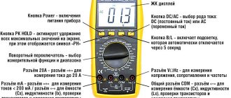
Symbols on the multimeter
A multimeter is an electrician's dream. There is no need to use multiple devices to switch from one operation to another.
The instrument scale is an important element. Incorrect operation leads to measurement errors or malfunction of the device. To do this, you need to know all the symbols on it.
The scale consists of circular sectors with icons indicating parameters. Each sector is responsible for a specific parameter. They are all divided by lines.
The kit includes probes. Golden rule: plus is red, black is responsible for the rest. Probe connection sockets:
"COM" socket. This is a minus, mass. The black probe connects here
This is important when measuring polar parts. Hole “VΩCX+”. This is the positive socket to which the red wire is connected
It is used in all measurements except current. "10A" socket. Used to measure current up to 10 A. The value can be any - 20 A, 30 A. This is a very high current. It is important not to burn the device. If an inscription appears near the “UNFUSED” socket, then the measurement is carried out without a fuse. The multimeter can only be connected in series during the operation. "MACX". A probe is connected here to measure low currents - up to 0.2 A.
The red triangle with the warning label "MAX 750" indicates the voltage measurement limit. The number may vary.
If the measurement limits are not known, set the maximum on the scale. Do not touch the metal part of the probe under any circumstances - if in some cases this will lead to a measurement error, then in severe cases it will lead to electric shock.
Decoding the multimeter scale symbols by sector:
- "DCV" - constant voltage;
- "ACV" - alternating voltage measurement;
- "DCA" - constant current scale;
- "ACA" is the AC icon.
Designations on the resistance scale in the standard version: 20 Ohm, 200 Ohm, 2 kOhm, 20 kOhm, 200 kOhm, 2 MΩ, 20 MΩ, 200 MΩ. They may be different. To measure, the pen is placed in the “Ω” sector.
On some models, constant voltage is indicated by a dash with the letter V: “V—”. Alternating voltage - the letter V with a wave.
Alternating current
The symbol for alternating current is similar to alternating voltage - a wavy line followed by the letter A. To measure alternating current, rectifier diodes are introduced into the circuit. The tseshka is poorly suited for measuring this parameter. For this you need a current clamp.
D.C
The designation for direct current is similar to direct voltage - a solid or broken line near the letter A: “A—”. Direct current is designated "DCA" or simply "DC". The regulator is exhibited in this sector. To measure the parameter, we connect the circuit - the device in parallel. The parameter is measured in one conductor, so we include a multimeter in it, which, in addition to passing current, takes measurements.
Line connection
The standard package includes three probes with different characteristics and structures. One of them has two tips and is designed to combat leakage currents. On the top side of the device there are three sockets for connecting probes. Each of them is characterized by a corresponding letter marking:
- Z - for connecting protection grounding.
- L is the line that is being measured.
- E - screen (intended to eliminate leakage currents).
You might be interested in: Principles and sources of free energy according to the Tesla scheme
There are no other options, except for cases with shielded wiring. However, in private buildings such methods are not used, since the installation of cables with a screen is practically useless here. However, if you have this type of cable, you need to minimize the risk of leakage currents by using a probe with a split end. The wires of the shielding braid must be twisted into a bundle, adding to the general bundle of wires.
How to correct megohmmeter, megger, megohmmeter, megameter or something else?)
Attention, I'm telling the truth. I wrote about this in more detail here, but I’ll repeat it again. The correct device for measuring megaohms is called a megohmmeter. Previously, it was called a megohmmeter (for example, in a 1966 book it is called that). New times, new rules. It’s correct to call it a megohmmeter, so let’s use this name in our electrical life. And if megohmmeter is an outdated name, then other interpretations are simply incorrect and illiterate. Although you can, for example, call old devices with a handle, produced in the Soviet Union, megohmmeters, and new digital ones, for example, electronic ones like Sonel, call them megohmmeters. But this is my personal opinion, more of a joke than an opinion.