Pressure measurement
Pressure is a physical quantity that characterizes the stressed state of a medium (liquid or gaseous. Pressure arises as a result of the action of a force on the surface of a body. It determines the thermodynamic state of substances. Pressure largely determines the course of the technological process, the state of technological devices and their operating modes. With the task of measurement pressure has to be encountered in measuring certain technological parameters, for example, gas or steam flow, with changing thermodynamic parameters, liquid level, etc. Increased or decreased pressure (non-compliance with the regime) during the technological process in any apparatus can lead to a loss of product quality in the final stage of the process.
According to the International System of Units (SI), the unit of measurement for pressure is the pascal (Pa) - the pressure created by a force of 1 newton (N), uniformly distributed over a surface area of 1 m² and directed normal to it. For technical measurements, a technical atmosphere was adopted equal to the pressure produced by a force of 1 kgf (9.80665 N) per area of 1 cm². The variety of types of measured pressures, as well as the areas of their application in technology, has led to the use of non-system units along with the system pressure unit. These include bar, millimeter of mercury, kilogram-force per square centimeter, kilogram-force per square meter, millimeter of water.
Pressure instruments are used to monitor and control technological processes. These devices are used for direct or indirect comparison of the measured value with a measure. In industrial installations, the most common gauges are excess pressure gauges, which usually have a zero reference point (from atmospheric pressure). Narrow-limit pressure gauges are also used - pressure gauges with a non-zero scale.
Pressure meters are pressure gauges for excess pressure in gaseous media with an upper limit of measurement of no more than 40 kPa.
Vacuum gauges are instruments for measuring the pressure of rarefied gas.
Draft gauges are vacuum gauges for measuring the pressure of a rarefied gas with an upper measurement limit of no more than 40 kPa.
Pressure and vacuum gauges - designed to measure excess pressure and rarefied gas pressure.
Thrust and pressure gauges are pressure and vacuum gauges for gas media with an upper measurement limit of no more than 20 kPa.
Differential pressure gauges are instruments that measure the difference between two pressures.
Pressure gauges are used to measure constant and variable pressure in the direction.
Constant pressure is considered to be pressure that does not change or changes smoothly over time at a rate of no more than 1% / sec. from the sum of the upper measurement limits of the instruments.
Variable pressure is considered to be pressure that smoothly and repeatedly increases or decreases according to any periodic law at a rate of 1 to 10% / s of the sum of the upper measurement limits.
According to the principle of operation, pressure measuring instruments are divided into the following:
Liquid - based on balancing the measured pressure of the corresponding liquid column.
Deformation (spring) - measuring pressure by the amount of deformation of various elastic elements or by the force they develop.
Deadweight piston - in which the measured pressure is balanced by an external force acting on the piston.
Electrical - based either on the conversion of pressure into one of the electrical quantities, or on a change in the electrical properties of the material under the influence of pressure. Such a division is not complete and can be supplemented by measuring instruments based on other physical phenomena.
Liquid pressure measuring instruments with hydrostatic balancing.
In liquid devices with hydrostatic balancing, the measure of pressure measured is the height of the column of working fluid. Distilled water, mercury, ethyl alcohol, and transformer oil are used as a working fluid, called a barrier or manometric fluid. The choice of working fluid is determined by the range of pressure being measured, operating conditions and the required measurement accuracy.
Currently, the range of liquid pressure measuring instruments with hydrostatic balancing is significantly limited. In most cases, they are replaced by more advanced deformation measuring instruments.
Liquid pressure measuring instruments (pressure difference and vacuum) with hydrostatic balancing that are also used on process flows include float and bell differential pressure gauges. The operating principle of float differential pressure gauges is based on balancing the measured pressure difference with the hydrostatic pressure created by the column of working fluid filling the differential pressure gauge. A float differential pressure gauge consists of two communicating vessels. The area of one vessel is much larger than the other. The internal cavity of the communicating vessels is filled with working fluid (mercury or transformer oil) to the zero mark. The value of the measured pressure difference is judged by a reading device, the indicator of which is mechanically connected to a float located in the cavity of a wide vessel.
Float differential pressure gauges are designed for nominal pressure drops, the upper limits of which are limited to values from 6.3 kPa to 0.10 kPa. Such differential pressure gauges are used at static pressures of the measured medium of no more than 25 MPa. Accuracy class 1.0 and 1.5.
Float differential pressure gauges are designed for nominal pressure drops, the upper limits of which are limited to values from 6.3 kPa to 0.10 kPa. Such differential pressure gauges are used at static pressures of the measured medium of no more than 25 MPa. Accuracy class 1.0 and 1.5.
Bell differential pressure gauges of this type are a bell immersed in a working fluid and moving under the influence of a pressure difference. The counterforce is created by making the bell heavier as it rises and by reducing the bell's weight as it sinks. This is achieved by changing the hydrostatic lift force acting on the bell according to Archimedes' law.
Bell differential pressure gauges with hydrostatic balancing are highly sensitive and have been used to measure low pressures, differential pressures and vacuums.
Deformation pressure measuring instruments.
High accuracy, simplicity of design, reliability and low cost are the main factors responsible for the widespread use of deformation pressure measuring instruments in industry. These devices are designed to measure excess pressure and discharge of non-aggressive liquid and gaseous media.
The operating principle of deformation pressure measuring instruments is based on the use of elastic deformation of the sensing element or the force developed by it. The measure of the measured pressure in measuring instruments of this type is the deformation of the elastic element or the force developed by it. Three main forms of sensing elements are most widespread in measurement practice: tubular springs, bellows and membranes.
A tubular spring (Bourdon spring) is an elastic curved metal hollow tube, one of the ends of which can move, and the other is rigidly fixed. Tubular springs are used primarily to convert the measured pressure applied to the interior of the spring into proportional movement of its free end. The most common is a single-turn tubular spring, which is a tube bent in a circular arc with a usually oval cross-section. Under the influence of applied excess pressure, the tube unwinds, and under the influence of vacuum it twists. To transmit the movement of the free end of the strain-sensitive element to the pressure gauge pointer, sector and lever transmission mechanisms are used. With the help of a transmission mechanism, the movement of the free end of the tubular spring of several degrees or millimeters is converted into an angular movement of the arrow of 270 - 300 g.
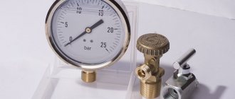
Pressure gauges have different scales depending on the parameter being monitored and are calibrated in kgf/cm2. The working area of the pressure gauge is in the middle of the scale and should be no more than 2/3 of the scale. To take readings, many instruments have reading devices (most often a scale or pointer). A scale is a set of marks located along a line or around a circle (pressure gauges), which depict a series of sequential numbers corresponding to the values of the medium being measured. The value of the measured quantity corresponding to one division is called the value of the scale division. The scale indicator is in most cases an arrow that allows you to read the value of the measured value on the scale. The scale usually indicates the accuracy class of the device.
A bellows is a thin-walled cylindrical shell with transverse corrugations capable of receiving significant movements under the influence of pressure or force. Under the action of an axial load, external or internal pressure, the length of the bellows changes, increasing or decreasing depending on the direction of the applied force. Within significant limits, the deformation of the bellows is proportional to the acting force, i.e., the bellows characteristic is linear. Within the linearity of the static characteristics of the bellows, the ratio of the force acting on it to the deformation caused by it remains constant and is called the rigidity of the bellows. To increase rigidity, a spring is often placed inside the bellows. Bellows are made from bronze of various grades, carbon steel, stainless steel, aluminum alloys, etc. Seamless and welded bellows with a diameter of 8 - 10 to 80 - 100 mm and a wall thickness of 0.1 - 0.3 mm are mass-produced.
Devices of this type are designed to measure excess pressure, vacuum and pressure difference.
Membranes are elastic and elastic. An elastic membrane is a flexible round flat (flat membrane) or corrugated (corrugated membrane) plate that can deflect under pressure. The static characteristic of flat membranes changes nonlinearly with increasing pressure, so here a small part of the possible stroke is used as the working section. Corrugated membranes can be used for larger deflections than flat ones, since they have significantly less nonlinearity of the characteristic. Membranes are made from various grades of steel, bronze, brass, etc. An elastic membrane, designed for measuring low pressures and pressure differences, consists of flat or corrugated disks sandwiched between flanges, made of rubberized fabric, Teflon, etc.
Measuring instruments with a sensitive membrane element are designed to measure atmospheric and excess pressure and vacuum. Due to the small forces developed by the sensitive deformation element, membrane devices are mainly produced as indicating devices. The principle of operation of the devices is to convert the measured pressure or vacuum into the movement of the rigid center of the sensitive membrane element, which, using a transmission mechanism, is converted into the rotational movement of the pointer.
Deadweight piston pressure gauges.
Deadweight piston pressure gauges are mainly used as reference and standard instruments for calibration and verification of various types of spring pressure gauges, since they differ from other types of pressure gauges in their high accuracy and wide measurement range.
The principle of operation is to balance the pressure acting on the piston on one side with the pressure of the loads on the other side.
Electrical pressure measuring instruments.
Electrical means of measuring pressure include currently produced pressure transducers based on the direct conversion method, which differ both in the type of strain-sensitive element and in the method of converting its movement or the force it develops into a signal of measuring information. For conversions, inductive, differential transformer, capacitive, strain gauge and other converting elements are used. The conversion of the force developed by the sensitive element into a signal of measuring information is carried out by piezoelectric elements.
Inductive pressure transducers - a membrane that senses pressure and is a movable armature of an electromagnet. Under the influence of the measured pressure, the membrane moves, which causes a change in the electrical resistance of the inductive converting element.
This quantity is usually measured by AC bridges or resonant circuits. followed by display on the instrument scale.
Differential - transformer converter - contains a strain-sensitive element and a strain-transformer converter. The differential-transformer converter contains a dielectric frame on which a coil with a primary winding is placed, consisting of two sections and two sections of the secondary winding. Inside the coil channel there is a movable core made of soft magnetic material, connected to a spring by a rod. A divider consisting of an adjustable and a constant resistor is connected to the output of the secondary winding. The principle of operation is based on the occurrence of a magnetic flux that penetrates both sections of the secondary winding and induces an EMF in them when a current signal flows through the primary winding. The output signal is determined by the mutual inductance between the primary winding and the output circuit and can be represented as an AC voltage signal. The conversion of the measured pressure is carried out by converting the pressure into deformation (movement) of the sensing element and subsequent conversion into an electrical signal arriving at the indicating device in the control room.
Capacitive transducer - pressure measurement is based on the dependence of the capacitance of the transducing element on the movement of the membrane under the influence of the measured pressure. The converter consists of a metal membrane, which is a movable electrode of a capacitive converting element and a stationary electrode isolated from the housing using quartz insulators.
Strain-resistor transducers are devices equipped with strain-resistor type conversion elements and are called strain-resistor pressure measuring transducers. Pressure transducers of this type are a sensitive deformation element, most often a membrane, onto which strain gauges (strain gauge) are glued or sprayed. The principle is based on the phenomenon of the strain effect, the essence of which is a change in the resistance of conductors and semiconductors during their deformation. Under the influence of the measured pressure, the deformable elastic element causes a proportional change in the electrical resistance of strain gauges assembled in a bridge circuit, which is further converted and amplified to form a unified analog output signal (4 - 20 mA).
Systems for measuring pressure of media in modern automated production use pressure measuring transducers (sensors) with output electrical current signals as primary transducers.
These sensors, in comparison with indicating pressure gauges, have a significantly higher accuracy class, are more labor-intensive to set up, and when checking require the use of exemplary high-precision measuring instruments at the input and output.
The figure shows a diagram of the electrical connection of instrumentation equipment that provides pressure control in a process plant.
The pressure transducer is installed in an explosive area or in a special cabinet on the territory of the process plant. As a rule, they do not have a scale that allows you to directly assess the pressure, but convert it into an electrical signal. The measured pressure acting on the strain gauge is converted by the electronic unit into a current signal, which is transmitted via an intrinsically safe two-wire transmission line to the terminal equipment and power supply located in a non-explosive (operator room or machine room) room.
The power supply provides power to the primary transducer (pressure sensor) and terminal equipment via the same line.
Step-by-step instructions on how to measure yourself
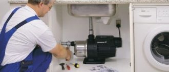
The owner of a private house should have complete information about the operation of the water supply, but the apartment owner should also sometimes measure the indicators. Installation of devices is simple and does not take much time. A step-by-step guide to measuring pressure without the help of specialists will help you avoid mistakes.
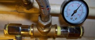
With pressure gauge
Installation of a stationary pressure gauge takes 1-3 hours . After unpacking and studying the assembly diagram, you can start working:
The pipe section is dismantled. Depending on the configuration, this can be done with a grinder or an adjustable wrench.- A section of water supply is assembled along with a measuring device.
- It is connected to the system.
- They do a test run. Check for leaks.
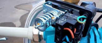
A portable pressure gauge is much faster and easier to assemble . It will take less than an hour:
- Connect the housing to the adapter.
- Disconnect one of the hoses that goes to the faucet or shower head.
- Measuring equipment is connected in its place.
Without meter
If it is not possible to buy measuring equipment, then you can use the contents of the pantry.
The first option is using a regular three-liter jar . To do this, you just need to measure how long it takes for the water to reach the neck:
- 8 seconds – 0.3 atmospheres;
- 1 second – more than 5 atmospheres.
The second option is a transparent hose . This method includes calculations, so you should stock up on pencil and paper:
The hose is hermetically connected in a vertical position to the mixer.- Fill the bend at the bottom of the structure with water (zero level).
- The top of the hose is clogged.
- Open the water to maximum.
- After 2 minutes, measure the distance from the zero level to the upper water boundary (a). And from it to the traffic jam (b).
- Calculate using the formula: (pressure[atm]) = 1 x (a+b) / b.
None of the proposed methods should cause any particular difficulties. It is worth repeating measurements to eliminate the possibility of error. The data obtained will be needed when the time comes to find out the causes of the problems.
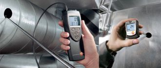
Automatic blood pressure monitor device
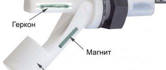
Automatic devices operate differently. To understand how an electronic tonometer works, you need to have an understanding of its design and the oscillometric measurement method.
The design of the automatic device includes:
- An electronic board with a display installed on it - it is responsible for controlling the buttons and pressure sensor;
- Pump for pumping air into the cuff;
- A sensor that records the level of pressure in the cuff. It also reads the pulse, upper and lower pressure, determines the presence of arrhythmia, i.e. heart rhythm disturbances;
- A valve that allows air to slowly deflate from the cuff when measuring pressure;
- Valve for quick air release.
Understanding what a tonometer consists of, it is easier to understand the mechanism of its operation and the rules of use.
Application of Liquid Pressure Gauge
The simplicity and reliability of measurements based on the hydrostatic method explain the widespread use of liquid-filled devices. Such pressure gauges are indispensable when conducting laboratory research or solving various technical problems. In particular, the instruments are used for the following types of measurements:
An important area of application of pipe pressure gauges with liquid filler is the verification of control and measuring instruments: draft gauges, pressure gauges, vacuum gauges, barometers, differential pressure gauges and some types of pressure gauges.
Features of wrist tonometers and semi-automatic devices
To measure blood pressure, you can use a tonometer that is worn on your wrist. They work in a similar way to conventional automatic tonometers, determining pressure and pulse values and displaying them on the display in the form of numbers. The only caveat is that readings are taken from the radial artery, where the amplitude of the pulse wave is less.
The difference between semi-automatic devices is the manual control of the pump. The person must pump up the air himself, and after reaching the desired pressure, the device automatically releases the pressure, releasing the air.
This difference is also associated with a slightly different design of the device. The design consists of a body with electronic filling, to which a cuff is attached, like an electronic blood pressure monitor. But there is also a mechanical bulb for pumping air, like mechanical models.
The cuff is fixed on the arm, and air is pumped into it using a bulb. Then you need to open the small valve on the bulb to gradually release the air. The electronic unit contains sensors that record the necessary sounds, so a phonendoscope is not required.
Design and principle of operation of a mechanical tonometer
Tonometers are either mechanical or automatic. There are also semi-automatic devices that can be classified into the second group. Each such device has its own design and mechanism of action.
A mechanical tonometer works using the auscultatory method of measuring pressure. This method of recording indicators was invented at the beginning of the 20th century and is still successfully used to this day. The design of the tonometer has not changed over the past decades; it consists of:
- Cuffs that fit on the shoulder between the elbow and shoulder joints;
- Supercharger - a pump that pumps air into the cuff;
- A pressure gauge showing the degree of air pressure in the cuff;
- A phonendoscope, with the help of which heart sounds are heard (they are also called Korotkoff sounds).
The operating principle of this type of tonometer involves detecting noise by ear. The cuff is placed on the arm and air is pumped into it until the artery is completely clamped. After increasing the pressure by another 30-40 mm Hg. the air is gradually released. This leads to the opening of the artery and the resumption of blood flow, which is accompanied by a certain sound. At the moment such noise appears, a digital indicator is recorded on the pressure gauge; it will be the value of the upper (systolic) pressure. When blood pressure decreases, a characteristic sound also appears, which is how the lower (diastolic) pressure is determined.
Liquid pressure gauges and differential pressure gauges, principle of operation, scope of application
Liquid (pipe) pressure gauges operate on the principle of communicating vessels - by balancing the fixed pressure with the weight of the filler liquid: the liquid column shifts to a height that is proportional to the applied load. Measurements based on the hydrostatic method are attractive due to their combination of simplicity, reliability, cost-effectiveness and high accuracy. A pressure gauge with liquid inside is optimal for measuring pressure drops within 7 kPa (in special versions - up to 500 kPa).