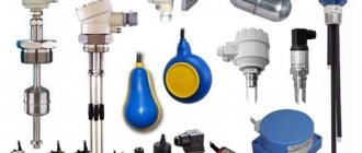
| The reed level sensor is an excellent solution for automating the level control process. This type of water level sensors combines the simplicity of the device and reliability of operation, while being a fairly economical solution. A reed level sensor can operate autonomously when used in small control systems, or be integrated into an existing automated process control system when automating large technological processes. |
What are reed sensors for water level monitoring?
Reed level sensors are an improved version of the simple mechanical level sensor. The only difference is that the mechanical switch is replaced with a reed switch. This increases the reliability and durability of the sensor.
Reed level sensors consist of two main elements - the reed switch itself and the float in which the magnet is located. The reed switch is a glass flask, inside of which there is a contact group that closes when a magnet approaches.
In the absence of liquid, the magnet does not act on the reed switch, the output circuit is in its original state. As the liquid level increases, the float will rise, thereby the magnet will close the reed switch, and the state of the output circuit will change. This is one of the simplest designs of float level sensors.
An excellent representative of this design of level switches is the model range of the FineTekFC series. The names of the models and their main technical characteristics are given below:
| Model | Process pressure | Process temperature | Liquid density | Load capacity | Housing material |
| FCH21PDD05X | up to 4 bar (excessive) | -20…+80°С | from 0.65 kg/liter | 50W max, 240V max, 0.5A max. | PP |
| FCH23FDD05X | 2 bar | -20…+120°С | from 0.85 kg/liter | 50W max, 240V max, 0.5A max. | PVDF (chemical resistant) |
| FCH11QDD05X | Atmospheric | -20…+80°С | from 0.78 kg/liter | 50W max., 240V AC/200V DC max., 0.5A max. | PP |
| FCH61PDA | up to 4 bar | -20…+80°С | from 0.55 kg/liter | 50W max., 240V AC max., 0.5A max. | PP |
Float level gauges and alarms, float level switch
Float level measuring instruments are widely used due to the simplicity of their design and fairly high accuracy.
The main elements of float level measuring instruments are a float, a transmission mechanism and a reading or recording device. When the liquid level changes, the float moves with it over the entire measuring range.
There are many design solutions for converters. Basically, these are level switches with a mechanical connection between a float and a measuring circuit, and the connection can be either flexible (thread, cable, tape) or rigid (lever, rack). When using float level gauges with a flexible coupling, it is extremely difficult to measure the level in vessels operating under pressure or requiring tightness, since when the flexible element is removed through the stuffing box, significant resistance arises, leading to level measurement errors. In these cases, it is preferable to use level gauges with magnetic coupling between the float and the measuring circuit.
To measure the level of homogeneous, non-precipitating, non-crystallizing liquids in various technological tanks, a float level switch and electrical level switches are used.
The principle of operation of the level switch (Fig. 1) is based on the dependence of the position of the float located in the measured medium on its level. When the liquid level changes, the position of the float 5, connected to a permanent magnet 4, changes. A similar permanent magnet 3 is housed in a sealed aluminum housing. Thanks to the magnetic connection of magnets oriented with like poles relative to each other, this movement controls the contact device 2 through the sealed wall. When the liquid reaches the upper limit position, the normally closed contact opens and the normally open contact closes.
Structurally, the alarm device consists of a float 5 with a magnet 4 fixed on the axis of the bracket 6, placed in a cast housing 1. For the level alarm (see Fig. 1, b), the magnet 4 and the float 5 interact with each other using stops 7 (magnet and float are independently mounted on axis 8, but the magnet is rigidly connected to brackets 9). In the level switch (see Fig. 1, c), the float 5 interacts with the magnet 4 using height-adjustable strips 10 located on a flexible cable stretched by counterweights 11. The operation error does not exceed ±3 mm.
Multiple Level Control
To solve more complex problems where it is necessary to control the level at several points, probe-type level sensors with magnetic switches can be used. In such sensors, the main element is a tube (probe), in which magnets with reverse polarity are located at different levels. Their number may be the same. There is also a design in which several magnets are located along the probe, but there is only one float.
An example of this type of alarm is Nivopoint sensors. They can have up to 5 magnetic switches, which allows you to control up to 5 level points, while the maximum probe length can be 4 meters. Which is more than sufficient for most tasks solved by this type of sensor.
Technical characteristics of Nivopoint sensors are presented below:
| Type | Material in contact with the environment of the parts | Media pressure | Medium density | Float size | Ambient temperature | dimensions |
| M.R. | stainless steel (DIN 1.4571 / BS 316Ti) | 2.5 MPa (25 bar) 1.6 MPa (16 bar) | min.0.8 g/cm3 min.0.55 g/cm3 min.0.4 g/cm3 | Ø53.5×60 mm Ø95 mm Ø124 mm | -40…+150°C | 116x80x65 mm |
| MP | PVDF float / PFA coating on sensing pipe | 0.5 MPa (5 bar) | min.0.4 g/cm3 min.0.7 g/cm3 | Ø76×87 mm | -40…+80°C | 116x80x65 mm |
| MR Ex | stainless steel (DIN 1.4571 / BS 316Ti) | 2.5 MPa (25 bar) 1.6 MPa (16 bar) | min.0.8 g/cm3 min.0.55 g/cm3 min.0.4 g/cm3 | Ø53.5×60 mm Ø95 mm Ø124 mm | +85°C(T6) +100°C(T5) +135°C(T4) +150°C(T3) | 124x80x65 mm |
Level determination of powders and other bulk materials
There are many types of relay switching technologies. So there are many ways to determine the level of powder and other bulk materials. With the release of Proximity Controls TFLS
(Tunable Vibrating Level Switch) and
LTS
(Tilt Switch) Series, Dwyer now offers five different spot level detection technologies for powder and other bulk materials.
These are: diaphragm , vane , tilt , capacitance and vibration .
Application of reed level sensors
Level control using reed switches and magnetic sensors is carried out in all industries where liquid products are used, such as:
- Water – drinks, aqueous solutions, waste water, etc.;
- Fuel, oils and some petroleum products;
- Chemical solutions, acid, alcohols, etc.
The possibility of use in environments with certain conditions (corrosivity, high temperature, high pressure, chemical resistance, etc.) is determined by the design features of individual sensor models. For example:
- For aggressive environments with high temperatures, an excellent solution would be FineTekFF magnetic level sensors, capable of operating at temperatures up to +350°C and made in Ex-version;
- For high process pressures and sub-zero temperatures, the solution is FineTekFD sensors, which can withstand pressures of up to 30 bar and can operate at temperatures down to -20°C.
This type of sensor can operate as a stand-alone device (which does not require power) or be integrated into an automation system. In this case, reed level switches solve the following problems:
- Limit level control (maximum, minimum);
- Tank level monitoring (Nivopoint sensors control up to 5 points);
- Protection of pumping equipment from dry running;
- Control of actuators to automate the process of filling/emptying containers.
At the same time, the switching capabilities of some sensors (for example, Nivomag) reach 10A, which allows you to use these alarms directly without an intermediate relay.
Electrical level gauges and alarms
Electrical methods of level measurement (electrical level gauges) include: electrical contact, conductometric and capacitive. In the general case, the level change is converted using a primary measuring transducer into an electrical signal, which is measured by devices for general industrial use.
Electrical contact level switches operate on the principle of determining where the contacts (sensitive element) of an electrical conductive circuit are closed by a liquid when its level changes. Due to their simplicity of design and high accuracy, electrical contact level switches are widely used.
Diagrams of the simplest electrical contact alarms and water level control relays are shown in (Fig. 2). The applicability of such alarms is determined by the magnitude of the current in their circuit and the value of the transition resistance of the controlled liquid in the circuit: signal electrode E1 - liquid - container wall (electrode E2).
In production conditions, the use of electrical contact level switches is limited due to one of their significant drawbacks: due to contamination of the insulator 1 electrode (caused by sedimentation on it, wettability, corrosion of the electrode and other reasons), a leakage current occurs, which leads to the appearance of “parasitic” conductivity from the signal electrode E1 to permanent electrode E2 over a contaminated insulator, i.e. in parallel with the liquid resistance (see Fig. 2, a) the leakage current circuit resistance Ry is connected. If the value of Ry is sufficiently small, a current arises in the circuit, causing a false operation of the water level relay or its false non-return when the level drops.
One of the effective methods for reducing leakage current is to install on insulator I (see Fig. 2, b) an electrode, the so-called “guard ring” - a ring metal electrode 2, to which a voltage of the same polarity is applied as to the winding of the liquid level relay , i.e. opposite to the signal electrode. In this case, the leakage circuit resistance Ry is closed almost entirely through the branch Rd, i.e. false positives are excluded. Signaling devices based on this scheme are especially indispensable when monitoring the level of foaming liquids, when the layer of foam above the liquid level is uncontrollable and can reach any value.
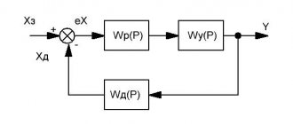
Rice. 1. Schemes of electrical contact level switches: a - direct connection; b - with a “security ring”; c - with a “break in the base” of the transistor
Rice. 2. Schematic diagram of the signaling device (one channel)
In order to reduce the operating current of the alarm (and increase the level of safety), the circuit shown in Fig. is often used. 2.c, where the “break” effect of the transistor base is used. The use of such circuits (despite their frankly captivating simplicity) raises serious objections, since when the level drops below electrode E1, the transistor most often fails due to the uncontrollability of the processes occurring in it when the base breaks.
The alarm consists of a relay unit and three sensors made of stainless steel.
The electrical circuit of the block (Fig. 3) consists of three transistor relay stages and a single power supply.
To ensure a response resistance of 5000 Ohms (first range), the contact sensor is connected to pin Ia. In order to reduce false alarms when the sensor is dirty, it is possible to connect sensors through contacts 2a, in which the response resistance is reduced to 700 Ohms. The schematic diagram does not require any special explanation. The level signaling error is ±5 MM, with the AC voltage at the electrodes not exceeding 7V. The sensors can be installed both vertically and horizontally.
There are practically no fundamentally new solutions for other types of electrical contact alarms; the differences are mainly of a design nature or the microelement base used.
Advantages and recommendations for the use of reed switch water level sensors
To summarize, we highlight the main advantages of reed level sensors:
- Simplicity of operation and design, hence high reliability;
- Easy installation and no need for configuration;
- Do not require electrical power to operate;
- Low price.
It is worth noting that, like any device, magnetic level switches have certain features that must be observed:
- Liquid density - on average, almost all sensors are designed for a density of 0.5 kg/l, but there are models designed for a value of 0.25 kg/l;
- Inability to work with substances with adhesive properties;
- Fluid dynamics - if the liquid in the container is fluttering, the float can move up and down, creating false alarms at the level boundary.
To reduce time and, most importantly, financial costs, you can seek advice on choosing reed level sensors from our engineers. They will help you choose a device that exactly matches the task you are facing.
Membrane and pendulum alarms
Diaphragm level switches
are intended for signaling the maximum levels of bulk non-caking materials in bunkers. The signaling device is mounted in the wall of the bunker (through a “window” corresponding to the controlled level). The pressure force of the bulk material acts on a flexible membrane with a rigid center and through a metal plate hinged on the bracket onto the switch. The sensors are located only on the vertical wall.
Pendulum (contact-mechanical) level switches
They operate on the principle of deflection under the action of bulk material entering the container, a sensitive element (plate or float made in the form of a pendulum with a hinged or flexible suspension) and its effect on a contact or non-contact switch.
Model range of reed switch water level switches
Next, you can familiarize yourself with the models on our website of magnetic level switches:
| Model | Process pressure | Process temperature | Liquid density | Load capacity | Peculiarities |
| Nivopoint | up to 2.5 MPa (25 bar) | -40…+150°С | from 0.5 kg/liter | 250V AC 3A per contact on switches (max. up to 9A) | Up to 5 levels, Ex-version, IP65 protection level. Vertical installation |
| Nivomag | up to 2.5 MPa (25 bar) | up to +250°С | from 0.7 kg/liter | 250V AC 10A 220V DC 0.6A | Ex-version, short circuit protection, IP68 protection level. Side installation |
| FineTekFF | up to 40 bar | up to +350°С | from 0.25 kg/liter | 60W max, 250V max, 5A max. | Ex-version, high-temperature version, versions for aggressive environments. Lateral and vertical installation |
| FineTekFC | up to 4 bar (excessive), atmospheric | -20…+120°С | from 0.55 kg/liter | 50W max., 240V AC/200V DC max., 0.5A max., max. conducted current 1A | Chemically resistant versions. Cable and plug connection. Lateral and vertical installation |
| FineTekFD | up to 30 bar | -20…+200°С | from 0.55 kg/liter | 50W max., 240V AC/200V DC max., 0.5A max., max. conducted current 1A | Cable and plug connection, incl. quick release Lateral and vertical installation. |
| FDMR | Atmospheric | up to +100°С | 0.5 kg/liter (use N5) 0.7 (use N8) | 240V AC/200V DC max., 0.5A max. | Flood sensor. Vertical installation |
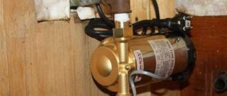
Float Switch - Pump Switch
The classic application of level switches is to control the switching on and off of pumps. The following figure shows two ways to connect a level sensor to the pump circuit: for filling the tank and for pumping out.
As already mentioned, the level relay has a NO and NC contact. In the figure, the brown and blue wires form a normally open contact, and the black and blue wires form a normally closed contact.
In the first case (water pumping mode), the pump is powered through a NO contact (not closed in the lower position of the sensor). When the liquid level reaches a predetermined level (the sensor floats up), its NO contact will close, turn on the pump, and begin pumping out the liquid. The pump will run until the sensor goes down again
When the pumps are running for filling, the situation is the opposite. The pump is powered via the NC contact of the sensor. This means that when the sensor is in the lower position, this contact is closed and the pump is running, the reservoir is filled with liquid. As soon as the sensor floats up, its NC contact will open and turn off the pump.
Conclusion
So, monitoring the condition of the oil in the engine lubrication system in modern cars is no longer an additional option, but an integral function. An electronic level gauge makes it easier to check the level, temperature, pressure, and in some modifications, the quality of the oil in the crankcase.
The malfunction of this sensor is quite a rare occurrence, but if necessary and desire to tinker around the car, it can be easily changed without the use of additional equipment. The main thing is to make sure that this particular element is faulty.
This video, using a VAZ 2110 as an example, shows where this leveler can be found and how to replace it:
Oil level sensor in the VAZ 2110 engine: what is it, where is it located and how to replace it!