Added March 5, 2022 at 10:15 pm
Save or share
If you've ever blown up a water heater or ever tried to make submersible electronics, you know how important it is to determine if there is water around. This water level sensor makes it very easy!
This sensor can be used to measure water level, monitor a septic tank, detect rain or detect leaks.
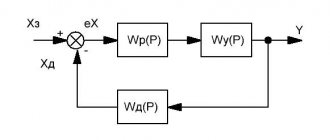
How a water level sensor works and its interaction with Arduino
Hardware overview
This sensor contains a series of ten open copper traces, five of which are power and five are sensitive.
These tracks are interleaved so that between every two supply tracks there is one sensing track.
Usually these paths are not connected to each other, but when immersed they are connected by water.
Figure 1 – Water level sensor
There is a power indicator on the board that lights up when power is applied to the board.
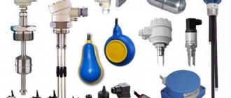
Types of hydrostatic level gauges
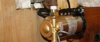
Hydraulic level sensors are available in two design options.
The first version is submersible pressure transducers, which are 2 blocks connected by a compensation cable. The measuring unit is an immersion probe. They are used for wells, wells, open tanks, and reservoirs. Also suitable for non-pressure tanks. Devices are made from different materials. The body can be stainless steel or polymer, and the sensitive membrane can be steel or ceramic. A reference pressure tube passes through the sheath of the compensation cable, and it can be Teflon, polyurethane or PVC.
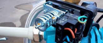
The second option is a mortise converter, suitable for horizontal installation in the tank wall. They have an open end membrane. Models can also be contact or non-contact.
Models are also classified by:
- Connection method: submersible, mortise, flange;
- Type of medium being measured: non-aggressive or aggressive, thick, abrasive, and so on;
- Method of communication with the atmosphere: for closed and open tanks.
How does a water level sensor work?
The operation of the water level sensor is quite simple.
A series of open parallel conductors together act as a variable resistor (potentiometer), the resistance of which changes depending on the water level.
The change in resistance corresponds to the distance from the top of the sensor to the surface of the water.
Figure 2 – Demonstration of the operation of the water level sensor
Resistance is inversely proportional to water height:
- the more water the sensor is immersed in, the better the conductivity and the lower the resistance;
- The less water in which the sensor is immersed, the worse the conductivity and the higher the resistance.
The sensor, in accordance with the resistance, produces an output voltage, by measuring which we can determine the water level.
Electromechanical solutions
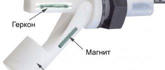
A common feature for such devices is the presence of a moving part, some type of float resting on the surface, or a device that must move through the contents.
Float - Using a float on the surface of a liquid is a simple and reliable method of measuring its level, provided that the contents do not obstruct free movement. There are a variety of valves, switches and position sensors that are float activated and provide level position recording or continuous reading over a limited range.
Some of the more modern designs for continuous float measurements use magnetostrictive sensing technology. The float is toroidal in shape and moves outside the tubular waveguide. Waveguides can be up to 50 feet (15 m) long, so they are used in very large tanks. The float contains a permanent magnet that causes the electrical pulse sent down the waveguide to be interrupted. The breakpoint is recorded with high repeatability and exceptional accuracy of ±<0.001 inch. Once the devices are installed and configured, no additional calibration is required.
“Magnetostrictive technology fits perfectly with wireless data transmission,” says Mike Geis, market development specialist for Ametek Automation & Process Technologies. “The response to the pulse is immediate, so current consumption is minimal.”
Two floats can be placed on the waveguide, making magnetostrictive measurements one of the few techniques that can provide continuous level measurements of liquid layers (such as oil on top of water) using a single instrument. “If the specific gravity differs by even 10%, we can develop special floats for level detection in multilayer liquids,” adds Geis.
Vibration and paddle wheel - These two methods are similar in that they involve immersing a moving probe into the contents. A vibration probe immersed in a material resembles a tuning fork, in which continuous vibration is created using a piezoelectric crystal. If the probe is not immersed in the contents, it vibrates freely. When diving, the nature of the vibration changes, which is recognized by the mechanism and the corresponding signal is sent.
Similarly, a paddle wheel uses a movable blade or fin-like flag mounted on a shaft attached to a small motor. When immersed in a solid product, the device cannot rotate and emits a signal. Once the contents are released, rotation resumes. Both methods use submersible sensors that are subjected to the destructive effects of the tank contents.
Pressure - Similar to mass measurements (tank weighing), pressure or differential pressure methods determine the level by measuring the head at the bottom of the tank (or where the instrument is located). If the tank is exposed to the atmosphere, you can get by with a regular pressure gauge. However, if the tank is closed and under pressure or is being pumped out, the reading of the differential pressure between the bottom and the free space in the upper part of the tank is used to automatically compensate for the difference in internal and atmospheric pressure. This method works well, but requires additional piping.
Water level sensor pinout
This water level sensor is very easy to use and has only 3 pins for connection.
Figure 3 – Pinout of the water level sensor
The S (Signal) pin is an analog output that will be connected to one of the analog inputs of your Arduino board.
The + (VCC) pin provides power to the sensor. It is recommended to power the sensor with a voltage of 3.3 to 5 V. Please note that the voltage at the analog output will depend on what supply voltage is supplied to the sensor.
— (GND) – ground.
Selection of methodology
One of the simplest and most reliable ways to determine the level of filling of a tank is to weigh it. This is the only method that gives the true mass regardless of whether the internal dimensions of the tank are known. The degree of filling of the tank can be determined using strain gauges placed under its support, subtracting its own weight. This method is suitable for any type of content and, provided there is no interference from piping or other connections, can provide highly accurate measurements. There are practical restrictions on overall overall dimensions, but this obvious solution cannot be overlooked.
If its use turns out to be impractical, one will have to resort to other, much more complex solutions, the applicability of which depends on a combination of various requirements.
The most common criterion when choosing a level measurement technique is the contents of the tank. For the purposes of this discussion, we define liquids as substances that settle at a uniform level and have the ability to flow through pipes. A solid-phase substance may have the same degree of fluidity, but does not necessarily form a uniform surface, nor does it flow down the walls of the vessel. The behavior of liquids with significant viscosity or a high solids content is more typical of bulk solids.
Below is a brief description of level measurement methods. Compare them based on the intended applications shown in the sidebar. Consider that continuous methods can be used to perform functions defined by a discrete level position, and a collection of point level measurements can be treated as continuous data, which can be useful despite their approximate nature. Both the list of applications and the overview of techniques are not exhaustive. For each application, there are methods that are not mentioned, and for each general case, justified exceptions are possible.
Connecting a water level sensor with Arduino
Let's connect the water level sensor to Arduino.
First you need to apply power to the sensor. To do this, you can connect the +(VCC) pin on the module to the 5V pin on the Arduino, and the -(GND) pin of the module to the GND pin of the Arduino.
However, one of the well-known problems with these sensors is their short lifespan when exposed to humid environments. By continuously supplying power to the probe, the corrosion rate increases significantly.
To overcome this problem, we recommend not constantly powering the sensor, but only turning it on when you are taking readings.
The easiest way to do this is to connect the VCC pin to the Arduino digital pin and set it to high or low when needed. So let's connect the VCC pin of the module to digital pin 7 of the Arduino.
Finally, connect the S (Signal) pin to the A0 pin of the Arduino A/D converter.
The connection diagram is shown in the following figure.
Figure 4 – Connection diagram of the water level sensor to Arduino
Electrical reflective methods
The advantage of ultrasonic and radar methods is that they can be used in numerous applications without any contact with the material. Since no access point to the tank is required (except for through spot measurements), the instruments are located at the top. Both methods are capable of overcoming various types of internal interference, and each has its own limitations in applicability.
Ultrasound - This technology can be implemented in a variety of ways, giving it flexibility. A sound pulse is sent into the tank, and the moment the echo returns is recorded by the sensor. Taking into account humidity and temperature, the distance to the surface can be calculated. Ultrasonic measurements are difficult in the presence of dust and foam; the variety of these problems depends on the area of application. In addition, this method can be used over a relatively limited range of pressures and temperatures compared to radar.
Various types of ultrasonic sensors can be mounted on the tank wall and provide point level measurement without penetrating the vessel. The echo of a sound pulse is detected if there is liquid or solid material on the other side of the wall. In some cases, the method makes it possible to distinguish the filling to a given level from the layer of sticky material covering the walls. This technical solution is especially useful in cases where capacity measurements are not possible and contact with the product, much less penetration into the tank, is unacceptable.
Radar - This technology has been around for over 25 years, but has only recently increased in popularity as capabilities have improved and operating costs have fallen. In the past, due to excessive cost, large size and high power consumption, radar sensors were used only in the most critical applications; Currently, the variety of ways to use this method is continuously expanding. Radar sensors are similar to ultrasonic sensors, but have fewer restrictions on their use and are more accurate: the microwave pulse has better ability to penetrate foam and dust, and is less affected by pressure and temperature.
Radar sensors can be configured for non-contact operation, or use a waveguide recessed into the contents of the tank. The non-contact design is used more often, but the waveguide configuration helps in situations where the fluid has a very low dielectric constant and is not capable of reflecting microwave radiation to a sufficient extent. “The waveguide design features a probe to transfer energy to and from the liquid surface,” says Carsella Vause, radar product manager.
Radar sensors are particularly suitable for use in reactors operating at high internal pressures and temperatures, as well as in the presence of aerosols, vapors, turbulence and other problematic conditions. “The biggest problem is foam,” says Carsella. "We ask - what is the dielectric constant of the liquid, what is the size or density of the bubbles, and what is the thickness of the foam layer?" He recommends waveguide designs because they have better penetration through thick foam layers.
A variety of radar sensor antenna configurations allow you to select the best solution to suit your tank interior and fluid characteristics. Moreover, it is possible to select the frequency in relation to the special properties of the liquid and severe operating conditions.
Basic example of water level detection
Once the circuit is assembled, upload the following sketch to the Arduino.
// Pins connected to the sensor #define sensorPower 7 #define sensorPin A0 // Variable for storing the water level value int val = 0; void setup() { // Set up D7 for output pinMode(sensorPower, OUTPUT); // Set the level low so that no power is supplied to the sensor digitalWrite(sensorPower, LOW); Serial.begin(9600); } void loop() { // get the reading from the function below and print it int level = readSensor(); Serial.print("Water level: "); Serial.println(level); delay(1000); } // This function is used to get readings int readSensor() { digitalWrite(sensorPower, HIGH); // Enable sensor delay(10); // Wait 10 milliseconds int val = analogRead(sensorPin); // Read the analog value from the sensor digitalWrite(sensorPower, LOW); // Turn off the sensor return val; // Return current reading }
Once the sketch is uploaded, open the serial port monitor window to see the Arduino output. You should see a value of 0 when the sensor is not touching anything. To see how water is detected, you can take a glass of water and slowly immerse the sensor in it.
Figure 5 – Displaying water level sensor readings
The sensor is not designed to be fully immersed, so be careful when experimenting to ensure that only the exposed traces on the circuit board come into contact with water.
Explanation
The sketch begins by declaring the Arduino pins to which the + (VCC) and S (signal) pins of the sensor are connected.
#define sensorPower 7 #define sensorPin A0
Next, we define the variable val, which stores the current value of the water level.
int val = 0;
Now in the setup() function we first configure the pin to power the sensor as an output and then set it to a low logic level so that no power is supplied to the sensor initially. We also set up serial communication with the computer.
pinMode(sensorPower, OUTPUT); digitalWrite(sensorPower, LOW); Serial.begin(9600);
In the loop() function, we periodically call the readSensor() function at one second intervals and print the return value.
int level = readSensor(); Serial.print("Water level: "); Serial.println(level); delay(1000);
The readSensor() function is used to get the current water level. It turns on the sensor, waits 10 milliseconds, reads the analog value from the sensor, turns off the sensor, and then returns the analog value.
int readSensor() { digitalWrite(sensorPower, HIGH); // Enable sensor delay(10); // Wait 10 milliseconds int val = analogRead(sensorPin); // Read the analog value from the sensor digitalWrite(sensorPower, LOW); // Turn off the sensor return val; // Return current reading }
Nuclear (radiation) sensors
Despite the high efficiency of this solution, it remains a method that is used last, due to its high cost and specialized requirements. The method is very simple: a radioactive source of gamma radiation is placed on one side of the tank. On the other side, sensors similar to a Geiger counter are mounted to read the level. The contents of the tank, solid or liquid, absorb gamma rays in a predictable manner, allowing the level to be determined electronically. The accuracy of the measurements is determined by the number of sensors, so this method is usually used to record the upper and lower limits.
Radiation sensors do not require penetration into the volume of the product, or even into the tank at all, so this method is especially valuable for installations with high pressure and temperature, when processing expensive products, and also when it is impractical to rework existing equipment. However, given the radioactive source's ability to radiate through a typical steel tank, handling it will require special permits and operator training, so this technical solution requires careful consideration and preparation.
Calibration
To get accurate readings from your water level sensor, it is recommended that you first calibrate it for the specific type of water you plan to monitor.
As you know, pure water does not conduct electricity. In fact, it is minerals and impurities that make it conductive. So your sensor may be more or less sensitive depending on the type of water you use.
Before you start monitoring data or running any event handlers, you need to see what readings you're actually getting from your sensor.
Using the sketch above, note what values your sensor produces when it is completely dry, when it is partially submerged, and when it is completely submerged.
For example, using the same circuit as above, you will see values similar to the following in the serial port monitor:
- when sensor is dry: 0;
- when it is partially immersed in water: ~420;
- when it is completely immersed: ~520.
Figure 6 - Water Level Sensor Calibration
This test may require some trial and error. Once you have good control over these readings, you can use them as thresholds if you intend to initiate any action. In the next example, we're going to do just that.
Design features and operating principle
The design of liquid level meters in a tank is determined by the following characteristics:
- Functionality. Based on this parameter, all measuring devices of this class are classified into level meters and liquid level alarms. The latter determine the specific filling point of the container (maximum and minimum), while the former constantly monitor the liquid level.
- Operating principle. This parameter is based on acoustics, optics, magnetism, electrical conductivity, and so on. The scope of its application depends on the principle of operation of the device.
- Measurement technique (non-contact or contact).
In addition, the design features of the device determine the type of process environment. For example, level gauges in drinking water tanks are different from devices that are designed to measure the fullness of tanks with industrial wastewater.
Water level determination project
For our next example, we're going to create a portable water level sensor that will light up LEDs based on the water level.
Connection diagram
We will use the diagram from the previous example. But this time we just need to add some LEDs.
Connect three LEDs to digital pins 2, 3 and 4 via 220 ohm current limiting resistors.
Assemble the circuit as shown below:
Figure 7 – Water level indication using LEDs
Arduino code
Once the circuit is assembled, upload the following sketch to the Arduino.
In this sketch, two variables are declared, namely lowerThreshold and upperThreshold. These variables represent our threshold levels.
Anything below the lower threshold turns on the red LED. Anything above the upper threshold turns on the green LED. Everything in between turns on the yellow LED.
/* Change these values based on your calibration values */ int lowerThreshold = 420; int upperThreshold = 520; // Pins connected to the sensor #define sensorPower 7 #define sensorPin A0 // Variable for storing the water level value int val = 0; //Declare the pins to which the LEDs are connected int redLED = 2; int yellowLED = 3; int greenLED = 4; void setup() { Serial.begin(9600); pinMode(sensorPower, OUTPUT); digitalWrite(sensorPower, LOW); // Configure the LED pins to output pinMode(redLED, OUTPUT); pinMode(yellowLED, OUTPUT); pinMode(greenLED, OUTPUT); // Initially turn off all LEDs digitalWrite(redLED, LOW); digitalWrite(yellowLED, LOW); digitalWrite(greenLED, LOW); } void loop() { int level = readSensor(); if (level == 0) { Serial.println("Water Level: Empty"); digitalWrite(redLED, LOW); digitalWrite(yellowLED, LOW); digitalWrite(greenLED, LOW); } else if (level > 0 && level <= lowerThreshold) { Serial.println("Water Level: Low"); digitalWrite(redLED, HIGH); digitalWrite(yellowLED, LOW); digitalWrite(greenLED, LOW); } else if (level > lowerThreshold && level <= upperThreshold) { Serial.println("Water Level: Medium"); digitalWrite(redLED, LOW); digitalWrite(yellowLED, HIGH); digitalWrite(greenLED, LOW); } else if (level > upperThreshold) { Serial.println("Water Level: High"); digitalWrite(redLED, LOW); digitalWrite(yellowLED, LOW); digitalWrite(greenLED, HIGH); } delay(1000); } // This function is used to get readings int readSensor() { digitalWrite(sensorPower, HIGH); delay(10); val = analogRead(sensorPin); digitalWrite(sensorPower, LOW); return val; }
Original article:
- How Water Level Sensor Works and Interface it with Arduino
Features of application
The use of ultrasonic meters has a number of features. For example, to eliminate measurement errors, you must follow the algorithm:
- carry out calibration of the device when the composition of the gaseous medium changes to establish the actual speed of sound;
- carry out calibration at each significant change in temperature, recording the speed values;
- In the future operation of the device when temperature changes occur, do not carry out calibration, but use previously recorded speed indicators.
The process of setting up the sensor is quite labor-intensive. A situation is possible when changes in the gas environment in the tank are not associated with changes in temperature. In this case, you will have to recalibrate the device.