Leveling staffs and their verification
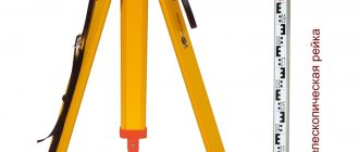
When leveling, three-meter folding double-sided or four-meter sliding slats (Figure 7.8).
On double-sided slats, centimeter divisions are painted on one side with black paint, the zero of which coincides with the heel of the slats (black side). On the reverse side, the divisions are painted in red paint (red side). On the red side with the heel of the staff, the readings are usually 4687, 4787, 4700 or 4800.
For levels with a reverse image of the pipe, the numbers are signed upside down. The divisions on the slats are united by five checkers, one of them in the form of the letter E, which makes it easier to take the count.
When leveling, the rod is placed vertically with zero down on pegs, crutches or shoes driven into the ground.
The rod is brought into a plumb position using a round level attached to it, and if there is no level, the rod is slowly rocked back and forth and the smallest reading is taken, which will correspond to the vertical position of the rod. Readings on the staff are taken along the middle horizontal stroke of the grid of threads with an accuracy of up to a millimeter. In this case, the number of decimeters and centimeters is counted using a rod, and millimeters are estimated by eye.
Currently, slats are made of wood, metal, and fiberglass. Moreover, on some types of slats, checker-type digitization is used (Figure 7.8), and on the reverse side the divisions are applied at millimeter intervals for leveling with a short beam (leveling arm - up to 20–30 m). Readings on such a scale can be taken with an accuracy of 0.1–0.5 mm (for high-precision leveling in construction and when observing settlements of structures).
Checking leveling rods.
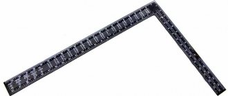
INSPECTION 1. The divisions of the slats must be sharply defined, equal to each other and correspond to the nominal length. A control ruler (meter) or a verified steel tape measure with millimeter divisions is placed on the rail and twice, in forward and reverse directions,
measure the lengths of the segments between divisions 1–10, 10–20 and 20–30 dm. The discrepancies between the lengths of the staff divisions and the corresponding tape divisions should not exceed 0.5 mm.
TEST 2. The difference in readings on the black and red sides of the working pair of slats should be equal to zero. When receiving a working pair of slats, it is necessary to check that the digitization of the heel of the slats on the red side is the same. To perform verification, 10–20 m from the level, place the first and second staffs alternately on a peg and take 3–4 readings on each side of the staff. The difference between the same readings should not deviate from zero by more than 2 mm. At the same time, the difference in readings along the red and black sides of each staff (heel difference) is determined. These differences during leveling make it possible to identify gross errors in the readings.
55. N i v e l i r o v a n i e IV class.
Class IV leveling is used when creating a high-altitude survey network (survey justification) for topographic surveys of the area. For class IV leveling, precision levels (models N-3, N-3K or their modifications) and checker rods are used. The distance at the station from the device to the slats should not exceed 100 m, and the inequality of the shoulders should not be more than 5 m.
The procedure for working at the station during class IV leveling is the same as for technical leveling, with the exception of monitoring the distances to the slats, which is determined by a thread rangefinder using readings along the upper rangefinder thread when observing the black sides of the rear and front slats.
The discrepancy between the elevations on the black and red sides of the slats at the station should not exceed ±5 mm.
The accuracy of class IV leveling is higher than technical leveling and is ±20 mm per 1 km of leveling course.
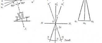
Rice. 7.3
Work at the station is carried out in the following sequence (see Fig. 7.3):
– leveling slats are installed on connecting points A and B, and a level is placed in the middle between them and brought into working position using lifting screws, installing a round bubble level at the zero point;
– point the level’s telescope at the rear staff (point A) and take a reading along the black side (Zchern);
– point the level’s telescope at the front staff (point B) and take readings first along the black side (Pchern), and then along the red side (Pkr);
– point the level telescope again at the rear staff and take a reading along the red side (Zkr);
– if there are intermediate points (C and D) between the connecting points A and B, then the back rail is installed on them sequentially and readings are taken only on the black side (chern and dblack). Before each reading on the staff, it is necessary to bring the sighting axis of the level telescope to a horizontal position using a cylindrical level bubble or compensator;
– to control measurements, calculate the differences between the zeros of the front and rear slats (Pkr - Pchern) and (Zkr - Zchern). Divergence of the differences between the zeros of the slats
absolute value should not exceed 5 mm;
– at each station, the excesses are calculated twice on the black and red sides of the slats: hchern = Zchern – Pchern; hkr = Zkr – Pkr. The discrepancy between these excesses should not be more than ± 5 mm;
– the height of the front point (B) is calculated through the average elevation hav = (hblack + hcr) / 2. using the formula HB = HA + hav;
– the heights of intermediate points (C and D) are calculated using the formulas GN = HA + Zchern, NS = GN – s, HD = GN – d.
Levels
A level is one of the main tools of a surveyor. The main purpose of these devices is to determine elevation differences between two points on the ground. At their core, they perform the same function as a regular building level. However, levels are designed to solve more important and responsible tasks, which determines their more complex design and operating principle. The need for leveling arises when performing geodetic work in a variety of directions. These devices are used in construction, road work, geological exploration, geodesy, cartography and topography, and installation work in any industry. Almost always, when performing such tasks, it is necessary to ensure a horizontal plane or a certain level of slope, which is where a geodetic level helps. This determines the significant demand for these devices in the modern market. The level is a device of a high level of accuracy. The level is one of the oldest types of geodetic instruments used by man. Its principle of operation has remained unchanged almost since the times of Ancient Egypt. However, today increasingly high demands are placed on the accuracy and functionality of these devices. Therefore, level production technologies are becoming more advanced and efficient. Modern leveling devices must provide the most accurate, simple and quick determination of height differences. In addition, they should be simple and easy to use. The main requirements for levels today: • maximum measurement accuracy; • light weight and compact design; • ease of operation; • the ability to save data on different media; • high reliability and resistance to external influences; • favorable cost. Types of levels Depending on different classification characteristics, levels are divided into several varieties. Thus, the following types of levels are divided into accuracy classes: • high-precision – accuracy less than 1 mm; • technical – accuracy from 1 mm to 2.5 mm. Another important feature is the design type and operating principle of the device. Based on this feature, the following types of levels are distinguished: • optical (the simplest and most affordable type of device); • digital; • laser. High-quality levels from the best manufacturers Our company offers its customers the opportunity to buy any type of level on favorable terms. Our assortment includes products from only the best manufacturers. These are devices capable of providing the highest measurement accuracy, high functionality, reliability and quality. You can also purchase from us all the necessary accessories for leveling and familiarize yourself with the full list of additional services, including warranty and post-warranty service, and metrological certification of devices. According to such an important criterion as price, the level must provide maximum economic efficiency for its owner. Therefore, we strive to offer our customers the most favorable prices for high-quality original devices. This is achieved through direct cooperation with manufacturers. Therefore, buying from us is truly profitable.
Mistakes that are made when using an optical level
For beginners starting to work with a level for the first time, it is important to take into account some features:
- It is important to ensure the safety of the device. Although it is protected by various types of coatings, it is sensitive to shocks and shocks. In order to completely eliminate device errors, you should make sure that all fasteners and parts are in working order and function properly.
- Don't miss the chance to use additional tripods and mounts. This will allow you to preserve the device even in the event of a sudden gust of wind.
- You should not completely trust the data provided in the instructions. It is worth checking the capabilities of the device yourself. If you are not buying a new device, it is better to have it verified at a specialized institution.
- Do not forget that when working with a level, you definitely need a partner.
- And when installing the rail, it must be positioned exactly on the surface to avoid distortions. Even if it is a ravine or hole, the ruler should rest against the bottom.
- Do not allow the device to overheat. This may affect the accuracy of measurements.
Operating rules
Working with the level is not particularly difficult. We offer you the simplest algorithm for using these measuring instruments, which will allow you, even without any special experience, to obtain the most accurate data and determine even the slightest deviations from the horizontal.
- It is necessary to correctly install the tripod, for which you loosen the fastening screws located on the legs, install the level horizontally on a stationary plane, and the measuring device should be located at chest level. Fasten the screws and fix the legs.
- A telescope is installed on a tripod and secured with a mounting screw.
- The level is brought to a horizontal position, for which three adjustment screws are rotated and the air bubble is placed in the central position on the round screen in the viewfinder.
- The optics are being focused and adjusted. The eyepiece should be adjusted to the operator's vision. To do this, the device is pointed at a large illuminated object, after which, by rotating the ring on the eyepiece, a clear image is achieved.
- To work, you will need two geodetic slats, which can be 3 or 5 meters long. The slats are marked in millimeters on one side and in centimeters on the other. They can be made telescopic from plastic or aluminum and folding from wood.
- Height alignment. The surveying rod is installed as close as possible to the point that needs to be measured and leveled. In the eyepiece it will be possible to observe the center line of the reticle, the data from which is recorded on paper or electronic media. Next, similar measurements are taken with other points, the area along which the alignment will be determined is determined, and based on the calculations obtained, it will be possible to ensure the most accurate and perfectly straight line.
- Centerline alignment will give you the most accurate data possible. It is necessary to choose a place where all the points are visible, through which you need to build a perfectly straight horizontal line. The level is installed in such a way that the nearest point is at least 5 meters away. The measuring rod is placed at the front of the device, and the second measuring rod is installed at the rear. The rear staff will be needed for marking, and the main staff at the front will allow you to calculate the height. The instrument is initially aimed at the rear staff, the values are recorded along the lines, after which the main staff is focused and data is recorded on the red side.
Modern laser and electronic devices can significantly simplify calculations. All information and all data are calculated automatically and then provided to the user in a readable form. Each of us can handle the use of such electronic and laser devices, even if he does not have the relevant work experience.
Levels are fairly easy- to-use devices that allow you to obtain geodetic data and determine the ideal geometry and horizontal plane. The use of such devices is not difficult, especially when used for measuring laser and electronic levels.
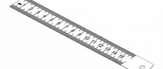
Measuring distances with an optical level.
There are two small lines on the vertical line of the crosshair. In order to measure the distance to the installed staff, you need to multiply the difference in readings by a constant for the Leica Jagger 20, like most other levels, the constant is 100.
Measuring distance with an optical level
- Top line – 291.2 cm
- Bottom line – 285.6 cm
- The difference is: 291.2 – 285.6 = 5.6 cm
- The distance to the rail in our case is 5.6 x 100 = 560 cm or 5.6 meters.
An optical level can measure long distances, depending on the magnification factor of the level optics. In particular, the Jagger 20 with a 20X magnification allowed me to measure distances up to 300 meters.
Errors when using an optical level
For beginners who are starting to work with the device for the first time, the following points must be taken into account:
- It is necessary to ensure the safety of the device. Although it is protected by various coatings, it is susceptible to impacts. To completely eliminate level errors, care should be taken to ensure that each fastening element and components work properly.
- You should use auxiliary tripods and fasteners. This will make it possible to preserve the device even during sudden gusts of wind.
- You should not blindly trust the information provided in the manual. It is better to check the functionality of the device yourself.
- It must be remembered that when using the device, the assistance of an assistant is important.
- When installing the rail, it must be exactly on the surface to avoid distortion.
- Do not allow the device to overheat, this may affect the accuracy of measurements.