Accuracy class
During laboratory measurements, it is necessary to know the accuracy of the measuring instruments, which in turn have certain characteristics and differ in design. Each of the measuring instruments (MI) has certain inaccuracies, which are divided into basic and additional. Situations often arise when it is not possible or simply not required to make a detailed calculation. Each measuring instrument is assigned a certain accuracy class, knowing which, you can find out its range of deviations.
Error. Accuracy classes of measuring instruments.
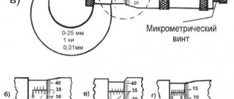
Let me first make a small digression. Concepts such as error and accuracy class are described in some detail in the regulatory documentation GOST 8.009-84 “Normed metrological characteristics of measuring instruments”, GOST 8.401-80 “Accuracy classes of measuring instruments. General requirements" and the like. But when opening these documents, a feeling of melancholy immediately arises... These concepts are explained so dryly and incomprehensibly to a simple beginning Kipovite. Let’s discard for now such fanciful and incomprehensible definitions as “the standard deviation of the random component of the error” or “the normalized autocorrelation function” or “the characteristic of the random component of the error from hysteresis - the variation H of the output signal (indication) of the measuring instrument”, etc. Let’s try to figure it out, and then put it into one small but understandable table, what an “error” is and what it can be.
Accuracy class
During laboratory measurements, it is necessary to know the accuracy of the measuring instruments, which in turn have certain characteristics and differ in design. Each of the measuring instruments (MI) has certain inaccuracies, which are divided into basic and additional. Situations often arise when it is not possible or simply not required to make a detailed calculation. Each measuring instrument is assigned a certain accuracy class, knowing which, you can find out its range of deviations.
Normalized error values will help you find out the errors of the measuring instrument in a timely manner. This definition should be understood as the limiting indicators for a measuring instrument. They can be different in size and depend on different conditions, but they should not be neglected in any case, because this can lead to a serious mistake in the future. The normalized values should be less than what the device shows. The limits of permissible error values and the necessary coefficients are entered in the passport of each dimensional measuring device. You can find out detailed standardization values for any device using the corresponding GOST.
Read also: Forests, volume 1 @ NATIONAL ATLAS OF RUSSIA
What is the accuracy class of the device?
An accuracy class is a characteristic of a device, which is determined by the limits of the permissible main and additional errors, as well as other properties provided for by the standards for this type of product that affect the accuracy. This parameter is present in the technical characteristics of many devices that have reference output parameters, be they electronic or mechanical measuring devices. The accuracy class is the main characteristic of measuring equipment: scales, multimeters, oscilloscopes, instrumentation equipment and others. The higher this value for a device, the more such a device costs, this is due to the complexity of producing such products.
Normalized error
Types of marking
The accuracy classes of absolutely all measuring instruments are subject to marking on the scale of these same instruments in the form of a number. Arabic numerals are used to indicate the percentage of normalized error. The designation of the accuracy class in a circle, for example the number 1.0, indicates that the error in the device’s needle readings will be equal to 1%.
If the designation uses a tick in addition to the number, this means that the scale length is used as a normalizing value.
Latin letters for designation are used if it is determined by the limits of absolute error.
There are devices on the scales of which there is no information about the accuracy class. In such cases, the absolute should be equated to one half of the smallest division.
Types of measurements
Measurement error is the amount of deviation from the true value of the measured indicators and quantities. The following formulas are used for calculation:
- Absolute error: Δ = Xd – Xmeas. It is calculated by subtracting the measured value from the real number. Expressed in units of measured indicators.
- Relative error: δ = (Δ ⁄ Xd)*100. Shows the percentage of deviation by absolute value and is calculated by the ratio of absolute to real, multiplied by 100%.
- Reduced error: γ = (Δ ⁄ Xн)*100. It is calculated based on the standard value, which allows you to specify the measurement range. In this case, the absolute value is divided by the normalizing value multiplied by 100%.
If there is a set of devices, then the overall characteristic is determined. First, the errors are brought to a single form, and then added up.
Limits
As mentioned earlier, the measuring device, thanks to standardization, already contains random and systematic errors. But it is worth remembering that they depend on the measurement method, conditions and other factors. In order for the value of the quantity to be measured to be 99% accurate, the measuring instrument must have minimal inaccuracy. The relative one should be about a third or a quarter less than the measurement error.
A Question of Choice
To install an electric meter in a private house or apartment, models that have a class of at least 2 are suitable.
In addition, when going to the store to buy an electric meter, you should know exactly the following characteristics:
- Phase of the electrical network. If the electrical network connected to the meter is single-phase, then the device must also be for a single-phase network. A three-phase electric meter can also be installed to track electricity usage, but such devices tend to be more expensive. When the meter is installed to measure three-phase current, the corresponding inscription must be indicated on it. Single-phase devices are not used to calculate three-phase current.
- The load under which this device will be operated. Depending on the maximum load that will be connected to the electricity metering device, a model is selected, on the body of which this indicator is indicated. For a standard load used in a private home, electric meter models designed for a maximum current of 60 A are used. If you plan to connect powerful electric heating boilers, then an electric meter is selected with an indicator of at least 100 A.
- If the electricity supplier can sell electricity at 2 tariffs, then the tariff of the meter is also taken into account when purchasing. Two-tariff devices allow you to save significantly on electricity bills. When using electricity at night, such a meter will record consumption separately. If the electricity supplier allows such payment, then installing a multi-tariff meter will allow you to use electricity more efficiently.
- Mounting method. Allows you to install the device in an existing box, or in place of a device that was previously installed.
ERRORS AND ACCURACY CLASSES OF ELECTRICAL INSTRUMENTS
ERRORS AND ACCURACY CLASSES OF ELECTRICAL INSTRUMENTS
The value measured by a device always differs from the true value by a certain number, called the device error. The errors of measuring instruments are determined by verification, i.e., by comparing the readings of the device being verified with the readings of a more accurate, standard device when they measure the same value. The value of the measured quantity, determined using a reference device, is considered to be valid. However, the actual value differs from the true one by the error inherent in this reference device. There are absolute, relative and reduced measurement errors.
ACCURACY OF MEASUREMENT INSTRUMENTS
The quality of a measuring device is characterized by its accuracy, which is assessed by the measurement error.
From the consideration of the above, it follows that impeccably accurate measurement of electrical quantities is technically impossible, i.e. the true value of the measured quantity cannot be determined using a measuring instrument. Therefore, the actual value of the measured quantity is taken as the true value.
The difference between the value of the quantity measured using the working device a
,, and its true value
a
is called the absolute measurement error:
The smaller the absolute error in comparison with the measured value, the higher the quality of the measurement. To characterize the measurement quality, the relative measurement error is introduced:
Since the magnitudes ai ah
differ little from each other, then often instead of
a
we substitute the value
a„
obtained directly from experience. The value of the absolute measurement error is influenced mainly by the error in readings, imperfection of measurement methods and the error of the instruments themselves.
Errors of electrical measuring instruments are divided into basic and additional. The main errors characterize the quality of the device itself; additional errors are caused by deviations of operating conditions from normal ones. The ratio of the largest value of the basic absolute error to the upper limit of measurement of the device determines the quality of the device itself. This ratio is called the reduced error. The given error is usually expressed as a percentage, and according to the value of the given error, all devices are divided into 8 accuracy classes: 0.05; 0.1; 0.2; 0.5; 1; 1.5; 2.5; 4.0. Devices that have a reduced error of more than 4% are considered extracurricular (these are panel and educational devices). However, the accuracy class of the device does not determine the accuracy of the measurement itself. To prove this position in the case where the absolute error does not depend on a
, multiply and divide the expression for the relative error by the upper limit of measurement am:
How to determine the accuracy class of an electrical measuring instrument, calculation formulas
To determine the accuracy class, you need to look at its case or user manual, in it you can see a number circled, for example , ① this means that your device measures a value with a relative error of ±1%.
But what to do if the relative error is known and it is necessary to calculate the accuracy class of, for example, an ammeter, voltmeter, etc. Let's look at the example of an ammeter: known ∆x=basic (absolute) error 0.025 (see instructions), number of divisions x=12
We find the relative error:
Y= 100×0.025/12=0.208 or 2.08%
( conclusion: accuracy class – 2.5).
It should be noted that the error is uneven over the entire scale range; by measuring a small value you can get the greatest inaccuracy and as the desired value increases, it decreases; for example, consider the following option:
Voltmeter with class p=±2, upper limit of device readings Xn=80V, number of divisions x=12
Absolute permissible error limit:
Relative error of one division:
If you need to perform a more detailed calculation, see GOST 8.401-80 clause 3.2.6.
V. Accuracy of measuring instruments.
The accuracy of a measuring device is its property that characterizes the degree of approximation of the readings of a given measuring device to the actual values of the measured value and is determined by the smallest value that can be determined reliably using this device.
The accuracy of the device depends on the value of the smallest division of its scale and is indicated either on the device itself or in the factory instructions (passport). Note that the measurement accuracy
is inversely proportional to the relative measurement error E: = .
The error of electrical measuring instruments is determined by the accuracy class (or reduced error Epr), which is indicated on the front side of the device with the corresponding number in a circle. The accuracy class of an instrument K is the ratio of the absolute error expressed as a percentage
to the limiting (nominal) value of the xpr of the measured value, i.e. to its greatest value that can be measured on the instrument scale (measurement limit):.
Knowing the accuracy class and measurement limit of the device, you can calculate its absolute error:
.
This error is the same for any measurement made using this device. Seven accuracy classes: 0.1; 0.2; 0.5; 1.0; 1.5; 2.5; 4.0. Devices of the first three accuracy classes (0.1; 0.2; 0.5) are called precision
and are used for precise scientific measurements, instruments of other accuracy classes are called
technical
. Devices without indicating the accuracy class are considered extracurricular.
Example . The current strength is measured in the circuit with an ammeter, the accuracy class of which is K = 0.5, and the scale has a measurement limit Ipr = 10 A. We find the absolute error of the ammeter:
It follows that the ammeter allows you to measure current with an accuracy of no more than 0.05 A, and therefore it is inappropriate to make a reading on the instrument scale with greater accuracy.
Let's assume that three current values were measured using this ammeter: I1=2 A; I2=5 A; I3=8 A. We find the relative error for each case:
; .
From this example it follows that in the third case the relative error is the smallest, that is, the larger the reading value on the device, the smaller the relative measurement error. That is why, for optimal use of instruments, it is recommended to select them so that the value of the measured value is at the end of the instrument scale. In this case, the relative error approaches the accuracy class of the device. If the accuracy of the device is unknown, then the absolute error is taken equal to half the value of the smallest division (ruler, thermometer, stopwatch). For calipers and micrometers – the accuracy of their verniers (0.1 mm, 0.01 mm).
Notes: 1) When making readings, make sure that the line of sight is perpendicular to the scale. To eliminate the so-called parallax error, many devices are equipped with a mirror (“mirror devices”). The experimenter's eye is positioned correctly if the instrument needle covers its image in the mirror.
2) For indirect measurements (for example, determining the volume of a cylinder by its diameter and height), all measured vertices should be determined with approximately the same relative accuracy.
3) When processing measurement results, it should be remembered that the accuracy of calculations must be consistent with the accuracy of the measurements themselves. Calculations performed with more decimal places than necessary result in a lot of unnecessary work. For example, if at least one of the quantities in any expression is defined with an accuracy of two significant figures, then there is no point in calculating the result with an accuracy of more than two significant figures. At the same time, in intermediate calculations it is recommended to save one extra digit, which later - when recording the final result - will be discarded. In the theory of errors, there is the following exception to the existing rounding rules: when rounding errors, the last digit retained is increased by one if the highest discarded digit is 3 or greater than 3.
4) Examples of final recording of measurement results:
Rationing
Accuracy classes of measuring instruments tell us information about the accuracy of such instruments, but at the same time it does not show the accuracy of the measurement performed using this measuring device. In order to identify in advance the error in the instrument readings, which it will indicate during measurement, people normalize the errors. To do this, they use already known normalized values.
Rationing is carried out according to:
- absolute;
- relative;
- given.
Formulas for calculating absolute error according to GOST 8.401
Each device from a specific group of devices for measuring dimensions has a certain value of inaccuracies. It may differ slightly from the established standardized indicator, but not exceed the general indicators. Each such unit has a passport in which the minimum and maximum error values are recorded, as well as coefficients that have an impact in certain situations.
Download GOST 8.401-80
All methods of standardizing measuring instruments and designating their accuracy classes are established in the relevant GOSTs.
What are they used for?
Various types of instrument transformers are found both in small matchbox-sized devices and in large power installations. Their main purpose is to reduce primary currents and voltages to the values required for measuring devices, protective relays and automation. The use of step-down coils provides protection for the lower and higher rank circuits, since they are separated from each other.
Reducing agents are divided according to characteristics of operation and are intended for:
- measurements. They transmit secondary current to devices;
- protection of current circuits;
- applications in laboratories. Such reducing agents have a high accuracy rating;
- repeated conversion, they belong to intermediate instruments.
Measurement
An instrument transformer is necessary to reduce the high current of the main voltage and transfer it to measuring devices. Connecting standard devices to a high-voltage network would require cumbersome installations. It is neither economically profitable nor advisable to sell instruments of this size.
The use of step-down transformers allows the use of conventional measuring devices in normal mode, which expands the range of their applications. Due to the reduced voltage, they do not require additional modifications. The transformer separates the high-voltage network voltage from the supply voltage of the devices, ensuring safety from use. The accuracy of electrical energy metering depends on their class.
Protection
In addition to powering measuring instruments, step-down transformers supply voltage to protection and automatic blocking systems. Because voltage drops and surges occur in the network electrical network, which is detrimental to high-precision circuit equipment.
In power plants, equipment is divided into power and secondary, which controls the processes of the primary device connection circuit. High-voltage equipment is located in open areas or devices. Secondary equipment is located on relay strips inside distribution cabinets.
The intermediate element for transmitting information between power units and measuring, control, monitoring and protection devices are step-down or instrument transformers. They separate the primary and secondary circuits from the harmful effects of power units on sensitive measuring instruments, and also protect operating personnel from damage.
Electrical measurements, accuracy class, error of measuring instruments.
Instruments for measuring electrical quantities must satisfy the following basic requirements (PUE):
1) the accuracy class of measuring instruments must be no worse than 2.5;
2) accuracy classes of measuring shunts, additional resistors, transformers and converters must be no worse than those given in table. 1.;
3) the measurement limits of instruments must be selected taking into account the possible largest long-term deviations of the measured quantities from the nominal values.
Accounting for active electrical energy should ensure the determination of the amount of energy: generated by ES generators; consumed per s. n. and economic needs (separately) of ES and PS; supplied to consumers via lines extending from the ES buses directly to consumers; transferred to or received from other energy systems; released to consumers from the electrical network. In addition, accounting for active electrical energy should provide the ability to: determine the flow of electrical energy into electrical networks of different voltage classes of the power system; compiling balances of electrical energy for self-supporting units of the energy system; monitoring compliance by consumers with their specified consumption regimes and balance of electrical energy.
Accounting for reactive electrical energy should provide the ability to determine the amount of reactive electrical energy received by the consumer from the power supply organization or transferred to it only if these data are used to make calculations or monitor compliance with the specified operating mode of compensating devices.
Current measurement must be carried out in circuits of all voltages where it is necessary for the systematic control of a technological process or equipment.
Direct current measurement in circuits: DC generators and power converters; AB, chargers, subchargers and discharge devices; excitation of SG, SC, as well as electric motors with controlled excitation.
DC ammeters must have double-sided scales if the direction of current can be reversed.
In three-phase current circuits, as a rule, the current of one phase should be measured.
The current measurement of each phase must be carried out:
for TG 12 MW or more; for overhead lines with phase-by-phase control, lines with longitudinal compensation and lines for which the possibility of long-term operation in open-phase mode is provided; in justified cases, it may be possible to measure the current of each phase of an overhead line of 330 kV and above with three-phase control; for electric arc furnaces.
Voltage measurements should be made:
1. On sections of DC and AC busbars, which can operate separately. It is allowed to install one device with switching to several measurement points. At a substation, voltage can be measured only on the LV side, if the installation of a VT on the HV side is not required for other purposes.
2. In circuits of direct and alternating current generators, SCs, as well as in some cases in circuits of special-purpose units.
When automatically starting generators or other units, installing devices for continuous voltage measurement on them is not necessary.
3. In SM excitation circuits from 1 MW or more.
4. In the circuits of power converters, batteries, chargers and rechargers.
5. In circuits of arc suppression coils.
In three-phase networks, as a rule, one phase-to-phase voltage is measured. In networks above 1 kV with an effectively grounded neutral, it is allowed to measure three phase-to-phase voltages to monitor the health of voltage circuits with one device (with switching).
The values of one phase-to-phase voltage of busbars of 110 kV and higher (or voltage deviation from the specified value) of electric power plants and substations, based on the voltage of which the power system mode is maintained, must be recorded.
Insulation monitoring . In AC networks above 1 kV with an isolated neutral or grounded through an arc suppression reactor, in AC networks up to 1 kV with an isolated neutral and in DC networks with isolated poles or with an isolated midpoint, as a rule, an automatic insulation monitoring must be carried out. to a signal when the insulation resistance of one of the phases (or poles) decreases below a specified value, followed by monitoring the voltage asymmetry using an indicating device (with switching). It is allowed to monitor insulation by periodic voltage measurements in order to visually monitor voltage asymmetry.
Power measurement:
1. Active and reactive power generators.
When installing panel indicating devices on a TG of 100 MW or more, their accuracy class must be at least 1.0.
ES 200 MW or more - total active power.
It is recommended to measure the total active power of an ES less than 200 MW if it is necessary to automatically transfer this parameter to a higher level of operational control.
2. Capacitor banks of 25 Mvar or more and SC reactive power.
3. Transformers and lines feeding the village. n. b kV and above ES, active power.
4. Step-up two-winding transformers ES - active and reactive. In circuits of step-up three-winding transformers (or autotransformers using a LV winding), the measurement of active and reactive power must be carried out on the MV and LV sides. for a transformer operating in a block with a generator, the power measurement on the NI side should be carried out in the generator circuit.
5. Step-down transformers 220 kV and above - active and reactive, 110-150 kV - active power.
In circuits of step-down two-winding transformers, power measurements should be made from the LV side, and in circuits of step-down three-winding transformers - from the MV and LV sides.
At 110-220 kV substations without switches on the overhead power side, power measurements may not be performed.
6. Lines 110 kV and above with two-way power supply, as well as bypass switches - active and reactive power.
7. On other elements of the substation, where periodic monitoring of network modes requires measurements of active and reactive power flows, it should be possible to connect portable monitoring devices.
registration must be carried out: the active power of the TG is 60 MW or more; total power of the power plant (200 MW or more).
Frequency measurement:
1. On each section of the generator voltage busbars.
2. At each TG of a block power plant or nuclear power plant.
3. On each system (section) of HV ES buses.
4. At the nodes of possible division of the power system into non-synchronously operating parts.
Registration of the frequency or its deviation from the specified value should be carried out: on power plants of 200 MW or more; at power plants of 6 MW or more, operating in isolation.
The absolute error of recording frequency meters on ES involved in power regulation should be no more than 0.1 Hz.
Synchronization measurements. For measurements with precise (manual or semi-automatic) synchronization, the following instruments should be provided: two voltmeters (or double voltmeter); two frequency counters (or double frequency counter); synchroscope.
Registration of electrical quantities in emergency modes. For automatic registration of emergency processes in the electrical part of power systems, automatic oscilloscopes must be provided. The placement of automatic oscilloscopes at objects, as well as the selection of electrical parameters recorded by them, are carried out according to the instructions of the PUE.
To determine the location of faults on overhead lines of 110 kV and higher with a length of more than 20 km, fixing devices must be provided.
Table 2. Characteristics of measuring instruments
Designation Device type Type of current Conversion How it is used Note Magnetoelectric (M)Logometer (M)
A, VR
C - constant, — coil currents
Electromagnetic (E)Logometer (E)
A, Vφ
, — currents of coils Electrodynamic (D)Logometer (D)
A, V, PA, V, P
, — coil currents- fixed coil current
Ferrodians-chesical (D)
Logometer (D)
A, V, Pφ,f
- fixed coil current Induction (I)Logometer (I)
,P, Q
N — disk revolutions of the Electrostaticchesical (C)
Thermal (T)
Rectifier (V)
VA, V
A, V
—Modern industrial enterprises and housing and communal services are characterized by the consumption of various types of energy: electricity, heat, gas, compressed air, etc. to monitor energy consumption, it is necessary to measure and record electrical and non-electrical quantities for the purpose of further processing of information.
In power supply, current (I), voltage (U), active and reactive power (P, Q), electricity (W), active, reactive and impedance (R, X, Z), frequency (f), power factor ( cosφ); in energy supply - temperature (Ө), pressure (p), energy consumption (G), thermal energy (E), movement (X), etc.
The range of instruments used in power supply for measuring electrical and non-electrical quantities is very diverse both in terms of measurement methods and in the complexity of the converters. Along with the direct assessment method, zero and differential methods are often used to increase accuracy.
Below is a brief description of the measuring instruments according to their operating principle.
Magnetoelectric devices have high sensitivity, low current consumption, poor overload capacity, and high measurement accuracy. Ammeters and voltmeters have linear scales, and are often used as standard instruments; they have low sensitivity to external magnetic fields.
Electromagnetic devices have low sensitivity, significant current consumption, good overload capacity, and low measurement accuracy. The scales are not linear and are linearized in the upper part by a special mechanism. They are often used as panel technical devices, simple and reliable in operation; sensitive to external magnetic fields.
Electrodynamic and ferrodynamic devices have low sensitivity, high current consumption, sensitivity to overloads, and high accuracy. Ammeters and voltmeters have nonlinear scales. An important positive feature is the same readings on direct and alternating currents, which allows you to check them on direct current. More often they are used as laboratory instruments.
Induction system devices are characterized by low sensitivity, significant current consumption, and insensitivity to overloads. They primarily serve as AC energy meters. Such devices are produced in single-, two- and three-element versions for operation in single-phase, three-phase three-wire, three-phase four-wire circuits. Current and voltage transformers are used to extend the limits.
Electrostatic devices have low sensitivity, but are sensitive to overloads and are used to measure voltage on direct and alternating currents. To extend the limits, capacitive and resistive dividers are used.
Thermoelectric devices are characterized by low sensitivity, high current consumption, low overload capacity, low accuracy and scale nonlinearity. However, their readings do not depend on the shape of the current over a wide frequency range. To expand the limits of ammeters, high-frequency current transformers are used.
Rectifier devices are characterized by high sensitivity, low current consumption, low overload capacity, and scale linearity. The instrument readings depend on the shape of the current. They are used as ammeters and voltmeters.
Digital electronic measuring instruments convert an analog input signal into a discrete one, representing it in digital form using a digital readout device (DRO) and can output information to an external device - a display, digital printing. The advantages of digital measuring instruments (DIM) are:
— automatic selection of the measurement range;
— automatic measurement process;
— outputting information in code to external devices;
— presentation of measurement results with high accuracy.
Types of ammeters
They can be electromechanical or analogue, digital or electronic. The basic set usually consists of a detector, a transmitter and an indicator, a recorder or a storage device.
Analog devices are the oldest instruments in use. Although they are reliable for static and stable measurements, they are not suitable for dynamic and transient conditions. In addition, they are quite bulky and have limitations due to the use of a dial indicator.
Electronic instruments respond faster and are able to instantly detect dynamic changes in current in the network. An example is a digital multimeter, which is capable of measuring dynamic or transient current values in seconds.
How to determine the accuracy class of a pressure gauge
A pressure gauge is a measuring device that allows you to determine the value of excess pressure acting in a pipeline or in the working parts of various types of equipment.
Such devices are widely used in heating systems, water supply, gas supply, and other utility networks for municipal and industrial purposes. Depending on the operating conditions of the meter, there are certain restrictions on the permissible limit of its error. Therefore, it is important to know how to determine the accuracy class of a pressure gauge.
What accuracy classes are there and how are they designated?
As we have already found out, the error interval is determined by the accuracy class. This value is calculated and established by GOST and technical conditions. Depending on the specified error, it can be: absolute, reduced, relative, see table below
According to GOST 8.401-80 in the SI system, accuracy classes are usually marked with a Latin letter, often with the addition of an index marked with a number. The smaller the error, respectively, the smaller the number and the higher the letter value in the alphabet, the higher the accuracy.
Devices capable of performing many different measurements can be of more than two classes at the same time.
The accuracy class is indicated on the device body as a number circled, indicating the range of measurement errors as a percentage. For example, the number ② indicates a relative error of ±2% . If there is a check mark next to the symbol, this means that the scale length is used as an auxiliary determination of the error.
- 0,1, 0,2 – considered the highest class
- 0,5, 1 – more often used for devices in the mid-price category, for example, household ones
- 1,5, 2,5 – used for measuring instruments with low accuracy or indicators, analog sensors
Note. On the body of high-precision meters, the class may not be applied. The designation of such devices is usually done with special symbols.
Standardization of errors of measuring instruments
Standardization of errors of measuring instruments
Standardization of metrological characteristics of measuring instruments consists in establishing boundaries for deviations of the real values of the parameters of measuring instruments from their nominal values.
Each measuring instrument is assigned certain nominal characteristics. The actual characteristics of measuring instruments do not coincide with the nominal ones, which determines their errors.
Usually the normalizing value is taken equal to:
- the greater of the measurement range if the zero mark is located at the edge or outside the measurement range;
- the sum of the modules of the measurement limits, if the zero mark is located inside the measurement range;
- the length of the scale or its part corresponding to the measurement range, if the scale is significantly uneven (for example, with an ohmmeter);
- the nominal value of the measured quantity, if one is established (for example, for a frequency meter with a nominal value of 50 Hz);
- module of the difference in measurement limits, if a scale with a conditional zero is adopted (for example, for temperature), etc.
Most often, the upper measurement limit of a given measuring instrument is taken as the normalizing value.
Deviations of the parameters of measuring instruments from their nominal values, causing measurement errors, cannot be indicated unambiguously, therefore maximum permissible values must be established for them.
The specified standardization is a guarantee of the interchangeability of measuring instruments.
Standardization of errors of measuring instruments consists of establishing a limit of permissible error.
This limit is understood as the largest (without taking into account the sign) error of a measuring instrument, at which it can be considered suitable and allowed for use.
The approach to normalizing the errors of measuring instruments is as follows:
- standards indicate the limits of permissible errors, which include both systematic and random components;
- separately standardize all properties of measuring instruments that affect their accuracy.
The standard establishes a series of limits of permissible errors. The same purpose is served by establishing accuracy classes of measuring instruments.
Accuracy classes of measuring instruments
The accuracy class is a generalized characteristic of an SI, expressed by the limits of the permissible values of its main and additional errors, as well as other characteristics that affect the accuracy. The accuracy class is not a direct assessment of the accuracy of measurements performed by this measuring instrument, since the error also depends on a number of factors: measurement method, measurement conditions, etc. The accuracy class only allows one to judge the limits within which the SI error of a given type lies. The general provisions for dividing measuring instruments by accuracy class are established by GOST 8.401–80.
The limits of permissible main error, determined by the accuracy class, are the interval in which the value of the main SI error lies.
SI accuracy classes are established in standards or technical specifications. The measuring instrument may have two or more accuracy classes. For example, if it has two or more measurement ranges of the same physical quantity, it can be assigned two or more accuracy classes. Instruments designed to measure several physical quantities may also have different accuracy classes for each measured quantity.
The limits of permissible main and additional errors are expressed in the form of reduced, relative or absolute errors. The choice of presentation form depends on the nature of the change in errors within the measurement range, as well as on the conditions of use and purpose of the SI.
The limits of the permissible absolute basic error are set according to one of the formulas: or , where x is the value of the measured quantity or the number of divisions counted on the scale; a, b are positive numbers independent of x. The first formula describes a purely additive error, and the second formula describes the sum of additive and multiplicative errors.
In technical documentation, accuracy classes established in the form of absolute errors are designated, for example, “Accuracy class M”, and on the device - with the letter “M”. Capital letters of the Latin alphabet or Roman numerals are used for designation, and smaller error limits should correspond to letters located closer to the beginning of the alphabet or smaller numbers. The limits of the permissible reduced basic error are determined by the formula, where xN is the normalizing value, expressed in the same units as; p is an abstract positive number selected from a range of values:
The normalizing value xN is set equal to the larger of the measurement limits (or modules) for SI with a uniform, almost uniform or power scale and for measuring transducers for which the zero value of the output signal is at the edge or outside the measurement range. For SI, the scale of which has a conventional zero, is equal to the modulus of the difference in measurement limits.
For instruments with a significantly uneven scale, xN is taken equal to the entire length of the scale or its part corresponding to the measurement range. In this case, the limits of absolute error are expressed, like the length of the scale, in units of length, and on the measuring instrument the accuracy class is conventionally indicated, for example, in the form of a symbol, where 0.5 is the value of the number p (Fig. 3.1).
Rice.
3.1. The front panel of a phase meter with an accuracy class of 0.5 with a significantly uneven lower scale
In the remaining cases considered, the accuracy class is designated by a specific number p, for example 1.5. The designation is applied to the dial, shield or body of the device (Fig. 3.2).
Rice.
3.2. The front panel of an ammeter of accuracy class 1.5 with a uniform scale
In the event that the absolute error is given by the formula, the limits of the permissible relative basic error
| ( 3.1) |
where c, d are abstract positive numbers selected from the series: ; – the largest (in absolute value) of the measurement limits. When using formula 3.1, the accuracy class is indicated in the form “0.02/0.01”, where the numerator is the specific value of the number c, the denominator is the number d (Fig. 3.3).
Rice.
3.3. Front panel of ampere-voltmeter accuracy class 0.02/0.01 with uniform scale
The limits of permissible relative main error are determined by the formula, if. The value of the constant number q is set in the same way as the value of the number p. The accuracy class for a device is indicated in the form , where 0.5 is the specific value of q (Fig. 3.4).
Rice.
3.4. The front panel of a megohmmeter of accuracy class 2.5 with an uneven scale
Standards and technical specifications for SI indicate the minimum value x0, starting from which the accepted method of expressing the limits of permissible relative error is applicable. The ratio xk/x0 is called the dynamic range of the measurement.
Construction rules and examples of designation of accuracy classes in documentation and on measuring instruments are given in Table 3.1.
Table 3.1. Designation of accuracy classes of measuring instruments
| Formula for determining the limits of permissible error | Examples of limits of permissible basic error | Accuracy class designation | |
| In documents | On funds | ||
| Absolute error | |||
| Accuracy class M | M | ||
| Accuracy class C | WITH | ||
| Reduced error | |||
| Accuracy class 1.5 | 1,5 | ||
| Accuracy class 0.5 | (for SI with non-uniform scale) | ||
| Relative error | |||
| Accuracy class 0.5 | |||
| Accuracy class 0.02/0.01 | 0,02/0,01 | ||
Control questions
- Explain what the SI accuracy class is.
- Is the accuracy class of an SI a direct assessment of the accuracy of the measurements performed by this SI?
- List the basic principles underlying the selection of standardized metrological characteristics of measuring instruments.
- How are devices standardized according to accuracy classes?
- What metrological characteristics describe the error of measuring instruments?
- How is the metrological characteristics of measuring instruments regulated?
Determination of error
Owners of measuring instruments are interested, first of all, in the maximum error characteristic of a pressure gauge. It depends not only on the accuracy class, but also on the measurement range. Thus, to obtain the error value, you need to make some calculations. For example, for a pressure gauge with a measurement range of 6 MPa and an accuracy class of 1.5, the error will be calculated using the formula 6*1.5/100=0.09 MPa.
It should be noted that only the main error can be calculated in this way.
Its value is determined by ideal operating conditions. It is influenced only by the design characteristics, as well as the assembly features of the device, for example, the accuracy of the graduation of divisions on the scale, the friction force in the measuring mechanism. However, this value may differ from the actual value, since there is also an additional error determined by the conditions in which the pressure gauge is operated. It can be affected by vibration of the pipeline or equipment, temperature, humidity level and other parameters.
Also, the accuracy of pressure measurement depends on another characteristic of the pressure gauge - the magnitude of its variation, which is determined during verification. This is the maximum difference in meter readings identified from the results of several measurements.
The magnitude of the variation largely depends on the design of the pressure gauge, namely on the method of balancing, which can be liquid (pressure from a liquid column) or mechanical (spring). Mechanical pressure gauges have a more pronounced variation, which is often due to additional friction due to poor lubrication or wear of parts, loss of spring elasticity and other factors.
Source:
3.4. Calculation of measurement system error
The measuring system is designed to perceive, process and store measurement information in the general case of heterogeneous physical quantities through various measuring channels (IC). Therefore, calculating the error of a measuring system comes down to estimating the errors of its individual IRs.
The resulting relative error of the IR will be
,
where x -
current value of the measured value;
—
the limit of a given channel measurement range at which the relative error is minimal; - relative errors calculated at the beginning and end of the range, respectively.
Since IR is a chain of various perceiving, converting and recording links, then to determine , ( x
) it is necessary, first of all, to estimate the standard deviation of the errors of these
m
links. Then the resulting standard deviation of the IR error will be
,
where are additional errors from n
influencing factors; ;— the limits of the permissible main error;— the quantile coefficient determined by the distribution law and the confidence probability of finding the error in a given interval.
Example 3.2.
Determine the error of the power measurement channel, the block diagram of which is shown in Fig.
3.10. Here CT and VT are current and voltage transformers, respectively; — power and current converters, respectively; K - switch; ADC is an analog-to-digital converter. Initial data: the relative error of the TT ,
given at the beginning of the measurement range, is , and at the end -; relative error of TN; The standard deviation error of power conversion consists of five components: the main error (1%); ripple errors (0.2%); additional error from changing cos φ (0.15%); errors from fluctuations in supply voltage (0.1%) and fluctuations in ambient temperature (0.6%); cos φ= 0.85; and from changes in ambient temperature; the error of a switch for 128 channels consists of three components: the error of the open key voltage drop (0.4%), the current leakage in each of the 127 channels closed by the key (0.13%) and the carrier frequency ripple (0.06%);
Rice. 3.10 Power measurement channel
Solution. 1. Considering that the law of error distribution is unknown, let us assume it to be uniform ( k
=1.73), and using formula (3.11) we find and.
For voltage transformer. Accepting the previous conditions,.