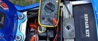
Checking the generator voltage regulator may be necessary when problems with the battery begin to occur. In particular, it began to undercharge or overcharge. When such a malfunction occurs, it’s time to check the generator voltage regulator relay.
The relay should turn off at 14.8 V
The task of this simple device is to regulate the voltage of the electric current that is supplied from the generator to the battery. When it fails, the battery is either not charged enough or, on the contrary, overcharged, which is also dangerous, since this significantly reduces the battery life.
Agree that the prospect of killing a battery because of one small part is not very good. This is why it is so important to monitor the operating condition of the voltage regulator (it can also be called a pill or a chocolate bar). But in order to properly check the voltage regulator, you need to know its type and several important features.
How to check the operation of a generator with a multimeter
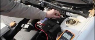
Checking the generator with a multimeter begins with measuring the voltage on the battery at idle and when turning on the interior equipment. The multimeter is switched to voltmeter mode, the red probe is applied to the “plus” of the battery, the black one to the negative terminal. After the engine is started, the voltage at the terminals should increase to 13.8-14.5 V.
Checking the generator with a multimeter
Checking the generator with a multimeter
It is allowed to increase the voltage on the multimeter display to 14.8 V - this indicator is considered normal for modern cars with a large number of electronic components.
To check whether the generator is overcharging the battery, turn on the high beams and heater and turn the engine to medium speed. If the generator is working properly, the voltage on the multimeter display does not increase.
Checking the voltage regulator
If, when checking the input voltage to the battery, it was determined that the level is insufficient, the voltage regulator is checked.
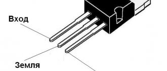
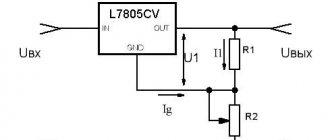
To check, you will need to switch the tester to voltmeter mode. Place the probes on the ground terminal of the generator and terminal 30 or “B+”. The readings on the display should be in the range of 13.5-14.6 V. If the readings are lower, the voltage regulator needs to be replaced.
Checking the diode bridge
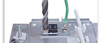
The most difficult thing to diagnose is the diode bridge, the so-called “horseshoe”. Its elements are located on a curved plate; it is very difficult to change power diodes in the form of disks - when installing them, soldering is not used, only welding; often the burnt-out element is simply cut out of the block. This reduces efficiency, but the unit remains in working order.
If the bridge diodes burn out, it is recommended not to repair the part, but to replace it with a new one. In 80% of cases, the diodes burn out after lighting the car.
It is better to check the bridge on a dismantled unit after complete disassembly. A breakdown often occurs when the polarity of the terminals is reversed, when the driver confuses the positions of the plus and minus terminals. Diodes with this problem burn out in pairs. A broken diode has zero resistance, the generator begins to quickly overheat, and the load on the car battery increases. You can tell that the diode has burned out by the characteristic burning smell that can be felt from under the hood.
Checking the generator diode bridge
Checking the generator diode bridge
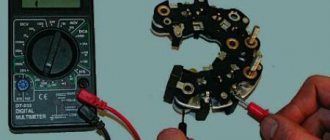
The multimeter is set to the “diode” position to test the continuity of the circuit. The first power diode on the horseshoe on the left has positive polarity. The resistance of a working diode is in one direction, when the red probe is applied to the diode, 400-700 ohms, (the black probe is applied to the horseshoe) when installing the black probe to the diode it tends to infinity.
The second diode on the horseshoe has negative polarity, therefore, when applying the positive probe of the multimeter to the output of the diode, the negative probe to the base of the horseshoe, the resistance should be infinite, when installing the black probe on the diode, and the red probe on the horseshoe within 400-700 Ohms. Each diode is dialed separately.
Winding check
The first sign of a burnt winding is a darkening of the color of the conductor insulation. The element uses copper winding and varnish insulation, which “flow” after a significant increase in temperature. During a short circuit, the color of the wire darkens, and drivers often feel a burning smell that appears at the installation site and intensifies when the engine is running. Winding burnout is determined visually; to do this, the unit must be removed and the inside of the rotor inspected through the ventilation holes.
Checking the generator winding
Checking the generator winding
Rewinding copper wire is impractical - it is cheaper to change the part by choosing a similar one with suitable seats.
You can check the stator with a multimeter by switching it to ohmmeter mode. Diagnostics are carried out on a removed unit, the winding resistance between the terminals is considered to be within 0.2 Ohm, the resistance between the neutral cable and the winding should be within 0.3 Ohm. The permissible error is 2%. If during measurement the resistance tends to zero, the starter is not suitable for use.
Checking with a multimeter without dismantling
You can check the condition of the relay using a multimeter. In this case, the generator is not dismantled. Before starting diagnostics, it is enough to clean the battery terminals (their oxidation can affect the operation of the car and the readings of the measuring device).
The diagnostic procedure is as follows:
- First you need to start the engine and let it warm up for a few minutes.
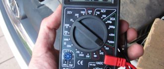
- Next, you need to connect the multimeter probes to the battery terminals. The device displays a value of 20V.
- After this, the voltage is measured. It should be within 13.2-14V. Such readings are considered normal for most cars.
- Now you need to increase the engine speed (up to 2-2.5 thousand). The voltage should increase by about 0.2V.
- If it exceeds 3,500 rpm, the multimeter should show 14-14.5V, but no more.
Serious deviations in the readings of the device indicate the presence of breakdowns of the relay regulator.
Signs of trouble
If the voltage is low, the battery will not be able to charge. Thus, the battery will quickly run out.
If, after the relay-regulator, the voltage goes to the battery at a high level (higher than set), the electrolyte will begin to boil and evaporate. At the same time, a white coating appears on the battery.
What signs of a breakdown of the car generator voltage regulator may be:
- After turning the ignition key, the warning lamp does not light up.
- After the engine starts, the battery indicator does not go out on the instrument panel.
- In the dark, you can observe how the light becomes brighter and dimmer.
- The car's internal combustion engine does not start the first time.
- If the engine speed exceeds 2000, then all the dashboard lights may turn off.
- Loss of engine power.
- Battery boiling.
Causes of relay malfunction
The reasons include the following observations:
- Short circuit (SC) on any line of automotive electrical wiring.
- Diodes are broken. The rectifier bridge has closed.
- The battery terminals are not connected correctly.
- Water got inside the relay.
- Mechanical damage to the housing.
- Brush wear.
- The relay resource has expired.
Tips and tricks
A common culprit for malfunctioning regulator relays may be oxidation of its terminals. This oxidation results in significant voltage loss. In this case, it is necessary to thoroughly clean the contacts and recheck. The voltage reading at the contacts should be similar to those given by the battery itself, that is, there should be no noticeable losses. Reduced voltage at the contacts indicates that they should be cleaned, and the regulator itself is often in working order. After cleaning, the terminals can be additionally treated with special chemicals that prevent further oxidation.
Finally, I would like to add that the cost of the regulator relay is not high. One of the surest ways would be to replace it with a new element if malfunctions are detected in its operation. Moreover, integrated relay regulators are a part in a monolithic housing that cannot be disassembled for repairs. Savings on this device are not justified, since rapid battery failure or a significant reduction in battery life will entail more serious costs when it is necessary to replace the battery.
Correctly charging a car battery with a charger. Before charging, check what current to charge the battery with. How to charge a battery without a charger.
The principle of operation and design of a car generator. The components of an alternator in a car: rotor, stator, windings, regulator.
How is the density of electrolyte in a battery measured, what does this indicator depend on. Affordable ways to increase the density in battery “banks” with your own hands.
For what reasons does the electrolyte in the battery become cloudy, gray or black? In what cases and in what ways can you restore battery functionality?
Why the starter may not work after turning the key in the ignition. The main causes of starter malfunctions: bendix, traction relay, brushes, winding.
Purpose, design features, installation location of the fuel pressure regulator of an injection engine. Signs of RTD malfunctions, checking the device.
A relay regulator is installed on cars to maintain stable voltage from the generator. This element protects the battery from overcharging, extending the battery life. It is the breakdown of the generator voltage regulator relay that is one of the most common malfunctions of the vehicle’s on-board network.
How to test a relay with a lamp
On many modern cars, the relay is combined with brushes. In this case, you can check the regulator using an incandescent lamp. The procedure will be as follows:
- To get to the part, you need to unscrew the mounting bolts and remove the terminals. The relay is located at the rear of the generator.
- To check, you need to prepare a 12V light bulb with a socket, wires, a voltmeter, and a power supply (no more than 20V).
- Next you will need to assemble the following circuit.
After connecting the light bulb, it should light up. At the same time, the voltage gradually increases. When it reaches 14.5V, the light should go out. If this happens later, it means the relay regulator is faulty.
Old type or check 591.3702-01
This is a very old type of relay; it was installed on “penny” cars, as well as on many rear-wheel drive cars. It has also always been separately mounted on the body, but the check here is slightly different in terms of contacts.
If you take their markings, then there are only two of them - “67” and “15”. The first contact “67” is a minus, as is the relay body itself, but “15” is a plus. The principle of operation is the same, we connect our charger - we start checking, increase the voltage to 14.5V, then look at the lamp. If it turns off well, no, it’s bad, replace it.
There is another “life hack” - if you connect a light bulb, bypassing the regulator relay, to the wires that went to pins 15 and 67, then remove the wire from the positive terminal of the battery - if the engine does not stall, then the generator is “live”.
Types and characteristics
Depending on the element base used, relay regulators are divided into the following types:
- Microcontroller or microprocessor based. Their peculiarity lies in the inclusion of a working algorithm in the built-in chip. Used in expensive cars, such as BMW or Audi.
- Relays are based on switching relay contacts to cut off and stabilize the performance of the electrical network.
- Integrated relays are widely used in the automotive industry. The operating principle is based on solid-state switching parts or integrated semiconductors.
- Hybrid transistor-relay devices and simply transistor ones are based on semiconductor elements. They were actively used in industry until the early 90s.
Based on their design, they are divided into the following types:
- External relays are separate devices that are installed on body structures.
- Built-in switching parts are an integral part of generators.
- Combined or hybrid. Their peculiarity lies in their combination with the brush assembly of an electric generator.
The purpose of the current regulator in a car
In a car and in other vehicles, for the normal functioning of electrical equipment and other systems, a direct current of -13.5–14.5 V is required. If the voltage does not reach the norm or, on the contrary, exceeds it, electrical appliances will begin to fail, and the battery due to excess charge will shorten its service life. The relay-regulator acts as a stabilizer of this on-board voltage within specified limits, depending on the electrical load, generator rotor speed and ambient temperature. It passes the permissible voltage into the vehicle’s on-board network, thereby providing it with the required parameters.
Voltage regulator relay
Design of the relay-regulator and external signs of its malfunction
- It can be made in the form of one of the modules of the brush assembly, using its structure as a supporting base.
- Or it is a separate element mounted on the body on a bracket.
The use of a separate design is easily visually detected due to the fact that the relay is located in the open circuit of the current flow between the generator and the battery. In any form of its design, the relay is a non-separable monoblock element, the body of which is filled with epoxy or other sealant. This means that a failed component cannot be repaired.
Failure of the relay regulator is accompanied by undercharging or overcharging of the battery. An undercharged battery results in
- the engine begins to start poorly;
- the starter is unable to crank the crankshaft;
- in severe cases, the car turns out to be de-energized and the remaining charge is not even enough to turn on the dashboard indicators.
An unpleasant consequence of overcharging a battery is boiling off of the electrolyte. At the same time, white deposits and streaks appear on its body in the area of the terminals and on the terminals themselves. External signs are not exhaustive and do not clearly indicate a relay malfunction. However, when they appear, a comprehensive check of the circuits and generator circuit is carried out, the list of procedures of which includes monitoring the serviceability of the relay regulator.
Repair or replacement?
It is more advisable to buy a new regulator. If it fails, the component parts of the element are seriously damaged. Of course, you can try to restore functionality, but in this case you risk being left with a broken generator somewhere outside the city.
By the way! On VAZ cars, you can try the following method as a temporary measure:
- remove the headlight bulb from the right headlight;
- We install one of its spirals on the terminals removed from the failed regulator.
If everything is done correctly, the emergency lamp will go out, and the one you need will light up and you will be able to get to the service center. However, remember that “folk” methods are used at your own peril and risk.
Types of regulator relays
Before you independently repair the voltage regulation device, you must take into account that there are several types of regulators:
- external – increase the maintainability of the generator
- built-in – in the rectifier plate or brush assembly
- regulating by minus - an additional wire appears
- positive regulating – economical connection scheme
- for alternating current generators - there is no function for limiting the voltage on the excitation winding, since it is built into the generator itself
- for DC generators – an additional option for cutting off the battery when the internal combustion engine is not working
- two-level - obsolete, rarely used, adjustment by springs and a small lever
- three-level – supplemented with a special comparison device board and a matching indicator
- multi-level - the circuit has 3 - 5 additional resistors and a tracking system
- transistor - not used in modern cars
- relay – improved feedback
- relay-transistor - universal circuit
- microprocessor - small dimensions, smooth adjustment of the lower/upper threshold of operation
- integral - built into brush holders, therefore they are replaced after the brushes wear out
DC generator relay
Thus, the connection diagram for the voltage regulator when operating a DC generator is more complicated. Since in the parking mode of the car, when the internal combustion engine is turned off, it is necessary to disconnect the generator from the battery.
During diagnostics, the relay is checked to perform its three functions:
- Battery cut off when the car is parked
- limiting the maximum current at the generator output
- voltage adjustment for field winding
Any malfunction requires repair.
Alternator relay
Unlike the previous case, diagnosing the alternator regulator yourself is a little simpler. The design of the “automotive power station” already includes the function of cutting off power from the battery while parked. All that remains is to check the voltage at the excitation winding and at the output from the generator.
If the car has an alternating current generator, it is impossible to start it by accelerating down a hill. Since there is no residual magnetization on the exciting winding here by default.
Built-in and external regulators
It is important for a car enthusiast to know that they measure and begin to regulate the relay voltage at a specific location where they are installed. Therefore, built-in modifications act directly on the generator, while external modifications “do not know” about its presence in the machine
Control by “+” and “–”
In principle, the control circuits for “minus” and “plus” differ only in the connection diagram:
- when installing the relay in the “+” gap, one brush is connected to “ground”, the other to the regulator terminal
- if you connect the relay to the “–” gap, then one brush needs to be connected to the “plus”, the other to the regulator
However, in the latter case, another wire will appear, since the voltage relay is an active type device. It requires individual nutrition, so “+” must be supplied separately.
Two-level
At the initial stage, mechanical two-level voltage regulators with a simple operating principle were installed in the machines:
- Electric current passes through the relay
- the resulting magnetic field attracts the lever
- the comparison device is a spring with a given force
- When the voltage increases, the contacts open
- less current flows to the exciting winding
Mechanical two-level relays were used in VAZ 21099 cars. The main disadvantage was working with increased wear of mechanical elements. Therefore, these devices have been replaced by electronic (contactless) voltage relays:
- voltage divider made of resistors
- The zener diode is the master device
Complex wiring and insufficient voltage control have led to a decrease in demand for these devices.
Three-level
However, two-level regulators, in turn, also gave way to more advanced three-level and multi-level devices:
- the voltage goes from the generator to a special circuit through a divider
- the information is processed, the actual voltage is compared with the minimum and maximum threshold values
- the mismatch signal regulates the current flowing to the exciting winding
Relays with frequency modulation are considered more advanced - they do not have the usual resistances, but the frequency of operation of the electronic key is increased. Control is carried out by logical circuits.
Generator device
The design of a car generator implies the presence of its own rectifier and control circuit. The generating part of the generator, using a stationary winding (stator), generates three-phase alternating current, which is then rectified by a series of six large diodes and the direct current charges the battery. Alternating current is induced by the rotating magnetic field of the winding (around the field winding or rotor). Next, the current is supplied to the electronic circuit through the brushes and slip rings.
Generator structure: 1.Nut. 2. Washer. 3.Pulley 4.Front cover. 5. Distance ring. 6.Rotor. 7.Stator. 8.Back cover. 9.Casing. 10. Gasket. 11.Protective sleeve. 12. Rectifier unit with capacitor. 13. Brush holder with voltage regulator.
The generator is located at the front of the car engine and is started using the crankshaft. The connection diagram and operating principle of a car generator are the same for any car. There are, of course, some differences, but they are usually associated with the quality of the manufactured product, the power and the layout of the components in the motor. All modern cars are equipped with alternating current generator sets, which include not only the generator itself, but also a voltage regulator. The regulator equally distributes the current in the excitation winding, and it is due to this that the power of the generator set itself fluctuates at a time when the voltage at the power output terminals remains unchanged.
New cars are most often equipped with an electronic unit on the voltage regulator, so the on-board computer can control the amount of load on the generator set. In turn, on hybrid cars the generator performs the work of the starter-generator; a similar circuit is used in other designs of the stop-start system.
The principle of operation of a car generator
Connection diagram for the VAZ 2110-2115 generator
The alternator connection diagram includes the following components:
- Battery.
- Generator.
- Fuse block.
- Ignition.
- Dashboard.
- Rectifier block and additional diodes.
The principle of operation is quite simple: when you turn on the ignition, the plus goes through the ignition switch through the fuse box, the light bulb, the diode bridge and goes through the resistor to the minus. When the light on the dashboard lights up, then the plus goes to the generator (to the excitation winding), then during the process of starting the engine, the pulley begins to rotate, the armature also rotates, due to electromagnetic induction, electromotive force is generated and alternating current appears.
The most dangerous thing for the generator is the short circuit of the heat sink plates connected to the “ground” and the “+” terminal of the generator by metal objects accidentally falling between them or conductive bridges formed by contamination.
Next, the diode passes plus into the rectifier block through a sine wave into the left arm, and minus into the right arm. Additional diodes on the light bulb cut off the negatives and only positives are obtained, then it goes to the dashboard assembly, and the diode that is there allows only the negative to pass through, as a result the light goes out and the positive then goes through the resistor and goes to the negative.
The principle of operation of a car DC generator can be explained as follows: a small direct current begins to flow through the excitation winding, which is regulated by the control unit and is maintained by it at a level of slightly more than 14 V. Most generators in a car are capable of generating at least 45 amperes. The generator operates at 3000 rpm and above - if you look at the ratio of the size of the fan belts for the pulleys, it will be two or three to one in relation to the engine frequency.
To avoid this, the plates and other parts of the generator rectifier are partially or completely covered with an insulating layer. The heat sinks are combined into a monolithic design of the rectifier unit mainly by mounting plates made of insulating material, reinforced with connecting bars.
Next, let's look at the connection diagram for a car generator using the example of a VAZ-2107 car.
Types of multimeters and the principle of their design
The most common types of multimeters are analog and digital. Let's look at how they are designed and work below.
Analog
These are old-style testers that look like boxes with a glazed arc-shaped scale and a spring-loaded pointer. Often there is a mirror arc on the scale so that when you look at the arrow you can align the arrow with its reflection. This way, when measuring, you are looking exactly perpendicular to the scale, rather than at an angle, and it will be more difficult for you to make a mistake. The measuring panel has many parallel arc scales for different types of measurements:
Analog multimeter.
One of the main advantages of an analog multimeter is its low price and measurement accuracy that is quite sufficient for everyday purposes. Moreover, most analog multimeters have a built-in special resistor to adjust the position of the arrow exactly to “0”. For adjustment, a resistor head is used, similar to a screw slot, located below the measuring scale approximately at the point where the arrow is attached.
Digital
These multimeters are more modern and look like oblong black boxes with a large liquid crystal display for digital readings. These devices got their name because the analog signals entering the device are converted into digital form in an analog-to-digital converter (ADC). Such devices are more expensive than analog ones, but their size and weight are somewhat smaller, and it is more convenient and faster to work with them.
Some models are well suited for working in complete darkness due to the ability to illuminate the indicator panel (and electricians often have to work in dark rooms). You simply press a button and the panel lights up. In addition, you can find a model with the ability to record the readings taken into the device’s memory and subsequently transfer this data to a computer for further analysis. To do this, just press a special button. Typically, digital devices are used by professional electricians, electronics engineers and engineers.
Digital multimeter.
The measurement kit includes two wires with terminals and pointed probes:
- one black wire – “minus”, “ground”, “com” (common);
- the second red wire is positive or “measuring”.
It will be interesting How to check a resistor with a multimeter
The black probe is usually applied to the body of the electrical appliance (common busbar) or attached with a special clip - an “alligator clip”. The red probe is most often taken in the right hand and applied to different places in the circuit. The probes included in the digital multimeter are the same as those in the analog multimeter. Often the sockets are color-coded - red and black frames, so as not to accidentally confuse which probe is inserted where.
Sometimes the multimeter is a built-in part of another device, such as a digital clamp meter. Due to the need to be large, such devices have a large amount of free space in their housing, where the multimeter is built in.
Brief summary
Based on the above, the following two conclusions can be drawn. Firstly, the relay-regulator can be pre-checked without removing it from the car. However, in the event of any malfunction, it will be impossible to determine whether the regulator is to blame, or whether something has burned out in the generator itself. Secondly, you can check the relay-regulator when removed in several ways. The choice of technique depends on the model of the device, as well as whether you have a power source with the ability to smoothly and accurately regulate the voltage.
How to check the relay - regulator without removing it from the car?
Indirect signs
If your “regulator” is out of order, you will notice it very quickly, especially if it is winter and frost outside. The fact is that there will be either an “undercharge” or an overcharge of the battery. If the charge is under-charged, you simply won’t start your car - you come to the parking lot, insert the key, and the car barely turns the engine, or doesn’t start at all, sometimes even the lights go out.
When recharging, almost the same thing will happen, only the reason will be boiling away of the electrolyte from the battery cans. It can be indirectly determined by the rapid decrease in electrolyte in the banks, and a white coating on the top of the battery, as well as on parts of the body underneath it. It’s worth thinking about it and checking the regulator relay.
However, this is not our method, we need to make sure more precisely.
Correct Method
To do this, we will use our voltmeter; we need to measure the voltage at the battery terminals with the engine running. To begin with, I would like to note that when the engine is not running, the normal voltage should be within 12.7V, perhaps a little less, but if you already have 12V, then the battery needs to be recharged! Or look for reasons for undercharging.
- Start the engine
- We set the multimeter to a value of up to 20 Volts
- Connecting the probes to the terminals
- If the voltage is approximately 13.2 - 14V, this is normal.
- We increase the speed (say to 2000 - 2500), the voltage will begin to increase, from about 13.6 to 14.2 V, this is also normal.
- Next, we try at maximum speed (more than 3500), the voltage should be from 14 to 14.5V, but no more!
If you have deviations, up or down, namely at any speed the voltage remains at 12.7V, or even drops to 12V, then this indicates a malfunction of the relay regulator.
Also, if the voltage is higher than 14.5V, for example - 15 - 16V, again the relay regulator is faulty and needs to be replaced.
To be completely honest, it is not always the relay that indicates a malfunction; often the generator itself fails. If the “regulator” is located separately, then you need to change it first; if nothing has changed, remove the generator and completely check the system. If the brush assembly is combined with the relay, then the generator must be removed!
What else could it be?
Often, the culprit for charging problems may not be the regulator itself, but its terminals; over time, like many on a car, they oxidize - which prevents the generator from working normally and recharging our battery, so first, before changing this unit, try to clean it, remove oxides and other deposits. By the way, this also applies to the battery terminals; they need to be cleaned and protected at least once a season.
Therefore, first of all, if the multimeter gives you 11 or slightly below 12V at the terminals of the machine, try cleaning the terminals and contacts first, then measure again. It is quite possible that this is the reason.
This is where I end the article, I think it was useful, read our AUTOBLOG.
Similar news
- Is there an automatic clutch? Let's look at the technical details...
- DIY brake caliper repair. Plus detailed video
- Spark plug gap. What should it be and what does it affect?
Add a comment Cancel reply
Replacing the voltage regulator on a Priora
How to repair a voltage regulator? On modern cars - no way. It is simply irreparable and a failed part is simply replaced with a new one. Theoretically, even an electronic non-contact voltage regulator can be repaired - but few people do this - there is no point.
So, how is the voltage regulator replaced on a Priora? First, you should turn off the ignition and disconnect the negative terminal from the battery for reasons of electrical equipment and your safety.
Be careful not to mix up the wires going to the voltage regulator of the Priora generator - otherwise you can ruin both the relay-regulator and the generator itself.
On a Lada Priora car, the voltage regulator is installed separately from the generator. To remove the relay-regulator, you need to unscrew the nuts that secure the device to the body. Before this, you need to mark with electrical tape, tape or a marker the relative positions of the wires leading to the contacts of the regulator, and the contacts themselves.
Now you can install a new voltage regulator on the Priora to replace the old one. It is imperative to check the contacts where the relay-regulator is connected to the generator, as well as the tension of the generator belt. That's it, connect the battery, tighten the terminals and check the operation. And, of course, we make sure that on the Lada Priora the on-board voltage does not jump, but is even.
If the relay-regulator is installed in the same housing with the generator, then the algorithm is slightly different. After removing the negative terminal from the battery, disconnect the wires going to the generator (there is no need to remove it itself).
We open the plugs or unscrew the fastenings of the relay-regulator, depending on the design of the unit. We remove the plastic casing of the generator and find the relay regulator. We unscrew the fastening nuts and disconnect the screw fastening to the tire. Let's extract it. All that remains is to install a new relay-regulator - we perform this procedure in the reverse order of removal.
To check the operation of a new device, in this case, you need to fully charge the battery, connect it as expected, and start the engine at about 2500-3000 rpm. Using a universal tester or a special voltmeter, you need to measure the voltage at the battery terminals.
If you replaced the relay regulator correctly, the number on the display will be equal to that indicated in the vehicle’s operating instructions. If not, the relay regulator should be replaced again. It is forbidden to check the serviceability of the relay-regulator by short-circuiting its terminals - this can lead to the “death” of the rectifier unit.
Video
Useful video for auto electricians.
How the generator and voltage relay work.
If you find problems with charging the battery from the generator, you need to check the regulator relay. This device is directly responsible for the normal operation and efficiency of battery charging. Moreover, the overall service life of the battery will depend on the health of the regulator relay.
The job of the regulator relay is to accurately maintain the voltage produced by the vehicle's alternator. In other words, the relay regulator functions as a voltage stabilizer. The device keeps the voltage within strictly specified limits, limiting the possible decrease or increase in the value. This regulation occurs constantly and does not depend in any way on the speed of the crankshaft and generator, as well as on the degree of load created by various consumers in the on-board network. It turns out that the relay regulator controls the “plus” of the battery, supplying or stopping the supply of electricity depending on the voltage reading at the battery terminal.
Read in this article
How to test a generator with a multimeter
The diode bridge of the generator can be checked with a multimeter, but you can also use the stand that was used to check the regulator.
But before that, first of all, without removing the rectifier bridge from the generator, connect the red wire of the tester to terminal 30 of the generator, and the black wire to the housing. Set the tester operating mode to dial (diode icon). If it is not there, then set it to 1-2 kOhm. The multimeter should show infinity. If the readings are different, the diode bridge is faulty.
Then check the current rectifiers for breakdown. Leave the positive (red) probe on terminal 30, touch the negative one to the bridge mounting bolts one by one. The multimeter display should show infinity in all cases; any others mean a breakdown.
Next, connect the positive probe to the axle mounting bolts, and the negative probe to the generator housing. In this case, the tester should also output infinity.
But in practice, such verification is most often not enough. In most cases, it is necessary to ring the generator in more detail.
Careful testing
To do this, unscrew the fastening bolts of the rectifier unit, disconnect the copper wires of the stator winding and remove the diode bridge from the generator. Now you can test each semiconductor individually. Before checking, it is advisable to rinse the stabilizer with running water using a medium-hard brush, and then dry thoroughly. For quick drying, a hair dryer is quite suitable.
Attach one of the tester probes to the diode plate, connect the second to the central terminal of each diode fixed to this plate. Then swap the probes. In one case, the multimeter should show infinity, in the other - a nominal resistance of approximately 570-590 Ohms. Rectifiers are considered faulty if:
- In the first and second measurements (when the polarity was changed), the multimeter readings are the same;
- Diode resistance is greater or less than nominal values.
Perform the same actions with the second plate of the diode bridge. If a fault is detected in one or more diodes, it will be easier to replace the entire rectifier unit. True, there are craftsmen who replace failed diodes individually, but such work requires a certain skill and dexterity.
Checking the armature and stator windings
Further inspection requires completely disassembling the generator. First of all, visually check the anchor. Brush rings should not show any blackening, chipping or wear on the treadmills. Blackening and slight wear can be smoothed out with zero-grade emery cloth. Rings with deep grooves must be replaced or, if the thickness of the rings allows, turned on a lathe.
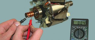
The armature winding should not clearly smell like burning. The color of the winding must be uniform and free of damage and breaks. To check the armature winding for a break, you will need a multimeter. Set the operating mode to continuity testing or resistance measurement and connect the probes to the brush rings. The winding resistance should be within 3-5 Ohms. Then leave one probe on the ring, connect the other to the body. The multimeter display should show infinity.
The generator stator is diagnosed after removal from the housing. First of all, carry out a visual inspection. There should be no visible damage to the wire or its insulation. Then connect the tester wire to the stator housing. With the second wire, touch the terminals one by one. There are only three of them. The tester must be in dialing mode. If the display shows infinity, this indicates that the stator is working properly.
Further testing consists of diagnosing the windings. The resistance of all three windings must be the same.
Before assembling the generator, you need to check and, if necessary, replace the bearings. When turning, they should not jam or make a creaking sound. This means that they are very worn out and will soon fail. Therefore, it is better to replace them immediately.
Checking the relay with a dismountable brush assembly and design as a separate module
It is often possible to test the relay-regulator as a separate module, which eliminates the effect of possible influence on the results of other circuits of the vehicle's electrical equipment. This procedure is possible when performing the relay:
- in the form of a separate built-in brush unit module;
- in the form of an independent functional unit, which is mounted in working position on the car body using a bracket.
In the first case, you will need to dismantle the brush assembly and additionally remove the relay from it. In the second case, the relay is disconnected from the wiring and, for convenience, removed from the mounting bracket. The further procedure is identical to the previous case. The only difference is that the input of the object under test will be directly the relay input.
The decision about the need to replace the relay is made in a similar way, that is, if it does not operate or if it operates at a voltage above 16 V. The strength of this testing scheme is the unambiguous conclusion about the technical condition of the relay and the precise localization of the failure location.
Checking the integral relay regulator
In the case of a relay-regulator in the form of a brush assembly module, a combined test is carried out. To complete it you will need:
- adjustable voltage source (its functions are performed by a charger);
- low-power car light bulb (for sidelights, turn signals or interior lighting);
- several connecting wires.
In addition, we disassemble the generator. To do this, unscrew one or more (depending on the version) mounting bolts, remove the brush assembly, which we clean from graphite dust. We connect an adjustable source to the input of the brush assembly, and a light bulb to its output, which coincides with the relay output. For some charger models, you will need to connect a battery in parallel to the output, otherwise the source will not turn on. Next, we turn on the source and change its output voltage, which is controlled using the built-in indicator or a multimeter. Taking into account the fact that brushes conduct electric current well, and the relay can be in two states and has a threshold characteristic:
- when the input voltage does not exceed 14.5 - 14.7 V, the light is on;
- If the specified value is exceeded, the relay is activated, which is indicated by the extinguished light.
If the light bulb continues to light at a voltage of 16 V or more, the relay is considered faulty and must be replaced.
Checking the removed part
You can also test the element removed from the generator. To do this, you need to turn on a 1–3 W, 12 V lamp between the brushes of the brush holder. It is necessary to connect the power supplies to the D+ and ground terminals in turn. First we connect the source to 12 V, then to 15–16 V. If everything is normal, then when connecting the first option the lamp will light up, and with the second it will go out. If it lights up in both places, it means there is a breakdown in the regulator. A lamp that is not lit at all indicates a break or lack of contact between the components. To check for contact, connect the lamp not to the brushes, but to the D+ and DF terminals.
Video about the scheme of working with the regulator on a VAZ 2109 car
Possible circumstances of malfunction
The main circumstances of malfunctions of generator voltage relay regulators are considered:
- interturn short circuit of the excitation winding. the most dangerous circumstance of a malfunction. After replacing the relay regulator, the generator works for a certain time without trouble. But the regulator operates at high currents and after a few months it burns out again. In this case
, you need to remove the generator and take it for testing; - failure of the rectifier bridge (diode breakdown). Less scary, especially since
this malfunction leads to overheating of the generator, and the diodes change first of all; - reversal or reversal of battery poles. In this case, the rectifier diodes also fail;
- destruction of brushes;
- short circuit at the control output of the relay regulator;
- natural wear and tear.
The consequences of a faulty relay regulator can be significant:
- increased generator voltage can lead to failure of the car's electronic components; therefore, the battery terminals should not be removed while the engine is running;
- internal short circuit of the relay-regulator leads to overheating of the excitation winding and, ultimately, more expensive repairs;
- destruction of the relay-regulator brushes can lead to final breakdown of the generator, its jamming, belt breakage and more important consequences.
Recommendations for increasing the service life of the regulator
In order to increase the service life of the voltage regulator, it is necessary to adhere to several simple rules aimed at implementing preventive measures. Among them:
- do not allow excessive contamination of the generator, periodically inspect its condition, and, if necessary, dismantle and clean the unit;
- check the tension of the alternator belt, tighten it if necessary (either yourself or in a car service);
- monitor the condition of the generator windings, in particular, do not allow them to darken;
- check the contact on the control wire of the relay-regulator, both its quality and the presence of oxidation on it;
- Perform periodic voltage checks on the vehicle battery with the engine running.
Following these simple rules will allow you to increase the resource and service life of both the generator and the vehicle voltage regulator.
Results
Checking the voltage regulator relay is not a difficult task, and almost any car enthusiast with basic repair skills can handle it. The main thing is to have the appropriate tools for this - a multimeter, a power supply with a voltage regulator (although you can connect it to a battery with a charger), a 12 V lamp and pieces of wires for mounting the appropriate circuit.
If during the inspection you find out that the regulator is out of order, then it must be replaced (repair work is usually not carried out). The main thing is not to make a mistake when choosing it and purchase the part that is suitable specifically for your car.
Ask in the comments. We will definitely answer!
Method for checking the voltage regulator of a scooter
Chinese scooters are designed in such a way that their relay-regulator, which is also called a voltage regulator, often burns out. The voltage regulator is an electrical circuit with 4 terminals for connecting to the scooter's electrical network.
A malfunction of the voltage regulator leads to very disastrous consequences:
At first, the instrument panel backlight lamps and the central low/high beam lamp burn out. This happens due to the fact that the voltage from the generator is not limited to 12 volts, which leads to the lamps receiving an increased voltage of 16 to 27 volts and higher. The voltage supplied to the lamps fluctuates and depends on the engine speed. Even at idle, the lamps shine so much that they blind, although they should shine at half their maximum brightness.
If you do not remove the malfunction of the voltage regulator and leave everything as is (many do this - they just drive without lights), then over time the battery will fail because its charging voltage exceeds the permissible one. If the voltage regulator is faulty, the battery receives a voltage of more than 15 volts, while the standard charging voltage should be between 13.5 - 14.8 volts. All this leads to the fact that the battery begins to leak - acid begins to penetrate through the valves. This is noticeable to the naked eye. And although when the normal charging mode is restored, the battery restores its operation, its service life is sharply reduced.
Also, if the voltage regulator is faulty, the battery stops charging correctly and loses its capacity. Therefore, it is not possible to start the scooter with the button. You have to start it from kickstarter.
I think it’s now clear how important it is to change a faulty voltage regulator on a Chinese scooter.
How to check the voltage regulator on a scooter? It is best (and most reliable) to do this without dismantling the voltage regulator itself. We will need at least some kind of multimeter with a voltmeter function. Any ordinary DT-830 or similar will do. What should be done? It is necessary to measure the voltage at the output of the voltage regulator.
How to check the charging relay, voltage regulator
In this video I will show you how to check
two-phase
relay voltage regulator
, also called charging relay...
How to check if the relay regulator on a motorcycle is working?
How to check
Is the bike's alternator working? — .
All measurements were carried out on a Chinese scooter ABM Storm L ZW50QT-16.
To get to the relay-regulator, unscrew the front fairing in which the central headlight is installed. We find there on the frame a box with 4 terminals: red, green, yellow and white.
We put the scooter on the stand and start it. After some time, the engine operation stabilizes at idle. Next, measure the voltage between the green and red wires. We set the multimeter in DC voltage measurement mode to the limit of 20V. Here's a look at how you can do it.
The display should display a voltage of about 14.6 - 14.8 volts, as in the photo. This is normal, standard voltage.
Then we need to measure the voltage that goes to the lighting lamps. The voltage to the central high/low beam lamp is not constant, but alternating (pulsating), so we switch the multimeter to the 20V alternating voltage measurement mode. On the multimeter that I used (Victor VC9805A+), you need to press the DC/AC (Alternating Current) button to do this. After this, we measure the voltage between the green and yellow wires. We simply move the probe from the red to the yellow wire, since the green wire is the common wire in the scooter’s electrical network.
The multimeter display should show a voltage of around 12 volts. It showed 11.4 - 11.6 volts. This is normal as the scooter is idling. If you have an assistant, you can ask him to accelerate a little to increase the engine speed and, consequently, the voltage from the generator. In any case, the voltage should not change much and should be around 12 volts.
This was a voltage measurement at the output of a working voltage regulator (relay regulator).
Now let’s see what a voltmeter shows when measuring the voltage at the output of a faulty scooter voltage regulator.
What problems might there be?
A small electronic or electromechanical part can lead to the following big problems:
- When the driver turns on the ignition, there is no light on the dashboard. Although, this may indicate a lost contact;
- When the startup is completed, there is no battery icon on the indicator part of the panel. This means that it is not charging at the moment. An almost unambiguous signal indicating a relay failure;
- The headlights shine stronger as the engine speed increases, and at idle they may not work at all. This is best seen not on the road surface, but if you stand opposite a light wall of a house or garage, and then press the gas pedal a little. This is the most reliable sign. Drivers from oncoming traffic will see everything as if the brightness is constantly jumping, smoothly or in sharp jerks;
- if the car does not start the first time, this means that all the current goes to the relay;
- Constant battery drain may also indicate this problem;
- If you add too many revs, the lights and instrument panel begin to dim. This triggers overvoltage protection. If it is an LED screen, then artifacts may appear on it or rainbow stains may appear on it;
- the car cannot gain enough speed, and the engine begins to slip, as if it is not able to overcome a certain milestone;
- If the battery boils, then it is definitely a faulty relay. But then you need to remove it from under the hood as quickly as possible, before the acid damages the paintwork, components and assemblies.
These are the most obvious problems; there are also minor defects, but only testing using special instruments can determine them.
Diagnostics of windings and contact groups
The winding is an inductance coil on which wire is wound in a spiral. It is characterized by a certain resistance, which is calculated according to Ohm's law. The resistance value should range from 10 to 100 Ohms.
Diagnostics of the winding allows you to find out whether its integrity is compromised. Functionality testing is carried out in several stages:
- The multimeter is turned on in resistance testing mode. On the instrument panel this mode is indicated by the symbol – Ω, the range is set within 2 kOhm.
- One measuring wire is connected to the socket, and the second to the COM.
- The wire probes touch the relay terminals.
The resistance of the inductor can be determined by the deflection of the arrow.
Main and additional fuse blocks
| F1 (16A) | Heater fan, rear window defroster, rear wiper and washer system, windshield washer pump |
| F2 (8A) | Steering column switch, windshield wipers, hazard warning lights, breaker relay (in turn signal mode), reverse light, instrument cluster (coolant temperature gauge, fuel level gauge, tachometer, warning lights: turn indicators, differential lock, parking brake, emergency condition of the working brake system, insufficient oil pressure, fuel reserve, battery charge) |
| F3 (8A) | Left headlight (high beam), high beam indicator lamp |
| F4 (8A) | Right headlight (high beam) |
| F5 (8A) | Left headlight (low beam) |
| F6 (8A) | Right headlight (low beam) |
| F7 (8A) | Side light lamps in the left front and left rear lights, license plate lights, side light control lamp |
| F8 (8A) | Side light lamps in the right front and right rear lamps, backlight lamps for the instrument cluster, cigarette lighter, switches, heating and ventilation control unit |
| F9 (8A) | Hazard switch, breaker relay (in hazard mode), tailgate defroster relay contacts |
| F10 (8A) | Sound signal, interior lamps, brake lamps in the rear lights |
| F11, F12 (8A) | Reserve |
| F13 (8A) | Fog light relay contacts in rear lights |
| F14 (16A) | Cigarette lighter |
| F15 (16A), F16 (8A) | Reserve |
| F11 (8A) | Turn signal lamps and relay-breaker for turn signals and hazard warning lights (in hazard warning mode) |
| F12 (8A) | Daytime running light relay, daytime running light bulbs |
| F13 (8A) | Rear Fog Lamps and Relays |
| F14 (16A) | Cigarette lighter |
| F15 (16A) | Spare |
| F16 (8A) | Spare |
| Fuse number and rating | Protected circuit |
| Main unit | |
| 1 (16A)* | Electric windows for front doors Electric side mirrors |
| 2 (16A)** | Air conditioning fan, air conditioning compressor |
| 9 (16A)* | Side mirror heaters |
| 10 (16A)* | Central interior lamp |
| Additional block | |
| 15 (16A)* | Air conditioning fan, air conditioning compressor |
Methods of checking on cars
Sometimes the generator fails on a car, motorcycle and other types of transport. There are the following options for solving the problem: repair at a service center, buying a new one, or repairing it yourself. In addition, immediately upon purchase, you need to check the charging of the battery generator. If the battery is new, then if attempts to charge it are unsuccessful, the battery may fail. The first two options require an investment of money, although many car enthusiasts prefer to solve the problem themselves. To troubleshoot basic problems, you need to know typical breakdowns:
- Bearing jamming.
- Winding combustion.
- Brush malfunction.
- Failure of the relay used in the U regulator.
When the bearings jam, the rotor becomes jammed and to eliminate this problem, you need to disassemble and lubricate the bearings. In addition, if they become unusable, then they need to be replaced with others.
If the windings of the rotor and stator coils burn out, they need to be checked with a tester for short-circuited turns, and if necessary, rewind. As a rule, brushes must be replaced, but there are cases of weakening of the springs necessary to absorb the rotation of the shaft and brush assembly. In this case, the springs also need to be replaced. The regulator relay U is responsible for charging the battery from the electric generator and if it fails, the battery is not charged at all.
Mostly, electrical problems occur and checking the generator on a car without removing it is quite simple. There are 2 ways to check: ring the generator with a multimeter and check the operation of the generator in the car under load.
Checking a car generator at home using a multimeter can be divided into several stages:
- Measure U at the battery terminals with the internal combustion engine (ICE) not running. U should be in the range: 12.6-12.8 V.
- Start the car and take measurements with the EG running. It should output U from 13.8 to 15 V.
- Connect the maximum load and measure U on the EG. The ideal option would be indicators of more than 13.8 V. If for some reason U is less than the required value, then the EG should be checked to ensure its performance.
To check, you need to know exactly the model and parameters of the electric generator: U, I, winding resistance (R). You need to disconnect it (EG) from the car's wiring and start calling it using a multimeter, and then compare the indicators with the required ones.
The second method is simple and gives results no worse than the first. The main steps for checking a generator for a VAZ (although this method can be used to check the EG for any type of transport):
- Start the engine and turn on electrical equipment, such as headlights (the load should be light).
- With the engine running, use a key to remove the negative terminal going to the battery.
- If during these manipulations the electrical equipment works normally, then the generator is working.
- Otherwise, you need to call it and, if possible, replace it (if the breakdown turns out to be serious).
Thus, there is no need to go to a service center to repair an automobile electric vehicle or buy a new one. First of all, you need to deal with the malfunction, because in most cases it turns out to be quite primitive and can be easily fixed even by an inexperienced car enthusiast.
Originally posted 2018-07-04 08:19:21.
Why does the diode bridge burn out?
There are many situations that can lead to diode failure. However, the most common breakdowns include the following:
- the board was flooded with water;
- dirt, together with engine oil, penetrated inside the bridge and led to a short circuit;
- The polarity of the contacts on the battery has been reversed.
Experts are considering several options for checking the functionality of the generator rectifier. The first method involves using a multimeter. In the second case, a standard car light bulb is sufficient.