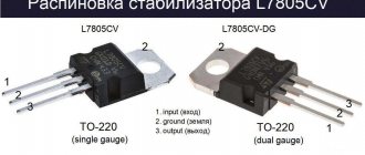
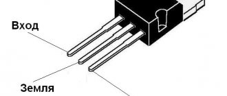
The L7805 CV integrated stabilizer is a conventional three-terminal 5V positive voltage regulator. Produced by STMircoelectronics, approximate price is about $1. Made in a standard TO-220 package (see figure), in which many transistors are made, however, its purpose is completely different.
In the marking of the 78XX series, the last two digits indicate the rating of the stabilized voltage, for example:
- 7805 - 5 V stabilization;
- 7812 - 12 V stabilization;
- 7815 - stabilization at 15 V, etc.
The 79 series is designed for negative output voltage.
Used to stabilize voltage in various low-voltage circuits. It is very convenient to use when it is necessary to ensure the accuracy of the supplied voltage; there is no need to install complex stabilization circuits, and all this can be replaced with one microcircuit and a couple of capacitors.
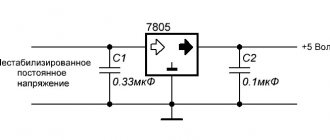
Connection diagram L7805CV
The connection diagram for the L 7805 CV is quite simple; to operate it is necessary, according to the datasheet, to place capacitors at the input of 0.33 μF and at the output of 0.1 μF. It is important during installation or design to place the capacitors as close as possible to the terminals of the microcircuit. This is done to ensure the maximum level of stabilization and reduce interference.
According to the characteristics, the L7805CV stabilizer is operational when supplying an input DC voltage ranging from 7.5 to 25 V. The output of the microcircuit will be a stable DC voltage of 5 Volts. This is the beauty of the L7805CV chip.
Definition of characteristics
To check the serviceability of the zener diode and compliance with the passport data, it is necessary to check its operation at different voltages. First you need to ring in resistance measurement mode. After making sure that there is no breakdown, a potential difference of 0.1 volt is set at the first and third contacts of the block. This is achieved by adjusting the resistor. The test takes place in DC voltage measurement mode . The anode of the zener diode being tested is connected to the third contact of the block, and the cathode is connected to the first. The tester probes are connected to them.
By adjusting the variable resistor, we increase the reverse voltage on the semiconductor until it stops changing. If this happens, it means that the zener diode has reached the stabilization voltage and is working normally. Sometimes it is necessary to determine its current-voltage characteristic. Then a tester operating in ammeter mode, connected in series with a zener diode, is added to the previous circuit. When the voltage changes with a certain step, the voltage and current values are taken, a graph is plotted, and a current-voltage characteristic is obtained.
The L7805 CV integrated stabilizer is a conventional three-terminal 5V positive voltage regulator. Produced by STMircoelectronics, approximate price is about $1. Made in a standard TO-220 package (see figure), in which many transistors are made, however, its purpose is completely different.
In the marking of the 78XX series, the last two digits indicate the rating of the stabilized voltage, for example:
- 7805 - 5 V stabilization;
- 7812 - 12 V stabilization;
- 7815 - stabilization at 15 V, etc.
The 79 series is designed for negative output voltage.
Used to stabilize voltage in various low-voltage circuits. It is very convenient to use when it is necessary to ensure the accuracy of the supplied voltage; there is no need to install complex stabilization circuits, and all this can be replaced with one microcircuit and a couple of capacitors.
Checking the functionality of the L7805CV
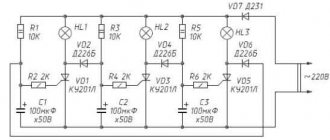
How to check the functionality of the microcircuit? To begin with, you can simply ring the terminals with a multimeter; if in at least one case a short is observed, then this clearly indicates a malfunction of the element. If you have a power source of 7 V or higher, you can assemble a circuit according to the datasheet given above and apply power to the input; at the output, use a multimeter to record the voltage at 5 V, so the element is absolutely operational. The third method is more labor-intensive if you do not have a power source. However, in this case, you will also receive a 5 V power supply in parallel. It is necessary to assemble a circuit with a rectifier bridge according to the figure presented below.
To check, you need a step-down transformer with a transformation ratio of 18 - 20 and a rectifier bridge, a further standard kit, two capacitors for the stabilizer and that’s it, the 5 V power supply is ready. The capacitor values here are overestimated in relation to the L7805 connection diagram in the datasheet, this is due to the fact that it is better to smooth out voltage ripples after the rectifier bridge. For safer operation, it is advisable to add an indication to visualize the device being turned on. Then the diagram will look like this:
If there are a lot of capacitors or any other capacitive load on the load, you can protect the stabilizer with a reverse diode to prevent the element from burning out when the capacitors are discharged.
The big advantage of the microcircuit is its fairly lightweight design and ease of use, if you need power of one value. Circuits sensitive to voltage values must be equipped with such stabilizers to protect elements sensitive to voltage surges.
L7805CV connection diagrams
Let's consider the output voltage regulation circuit. Such designs are based on the use of a simple technique. Its essence is as follows: as the potential difference at the GND stabilizer output increases, the potential difference at the output increases by the same amount. This can be achieved in three ways:
- using a resistor, connected to the ground terminal, the voltage at which is created by the current consumption of the stabilizer (Figure a);
- the current consumption of the stabilizer and divider R1 and R2 flows through the resistor (Figure b);
- using a zener diode (Figure c).
Based on this principle, the output voltage regulator circuit shown in the figure below is built. This circuit, with minor modifications, can be used, for example, to adjust the potential difference across the load depending on temperature. Depending on what type of temperature sensor is used, it can be connected instead of resistor R1 or R2.
Characteristics of the L7805CV stabilizer, its analogues
Main parameters of the L7805CV stabilizer:
- Input voltage - from 7 to 25 V;
- Power dissipation - 15 W;
- Output voltage - 4.75...5.25 V;
- Output current - up to 1.5 A.
The characteristics of the microcircuit are given in the table below; these values are valid provided that certain conditions are met. Namely, the temperature of the microcircuit is in the range from 0 to 125 degrees Celsius, the input voltage is 10 V, the output current is 500 mA (unless otherwise specified in the conditions, the Test conditions column), and the standard body kit with capacitors at the input is 0.33 μF and at the output 0 ,1 µF.
The table shows that the stabilizer behaves perfectly when powered at the input from 7 to 20 V and the output will stably output from 4.75 to 5.25 V. On the other hand, supplying higher values leads to a more significant spread of output values , therefore, above 25 V is not recommended, and a decrease in input less than 7 V will generally lead to a lack of voltage at the output of the stabilizer.
When operating at heavy loads , more than 5 W, it is necessary to install a radiator on the chip to avoid overheating of the stabilizer; the design allows this to be done without any questions. Naturally, such a stabilizer is not suitable for more precise (precision) equipment, because has a significant spread in the rated voltage when the input voltage changes.
Since the stabilizer is linear, it makes no sense to use it in powerful circuits; stabilization based on pulse-width modeling will be required, but for powering small devices such as phones, children's toys, radio tape recorders and other gadgets. The domestic analogue is KR142EN5A or in common parlance “KRENKA”. In terms of cost, the analogue is also in the same category.
Source: instrument.guru
Total
It has long been clear that such simple probes - attachments in amateur radio are just as necessary as very serious measuring instruments, but making them (tinkering with their manufacture) is simply too lazy, but in vain, and the understanding of this comes every time this simple device nevertheless, it was collected and provided invaluable assistance in creative endeavors. Author: Babay iz Barnaula .
Discuss the article HOW TO CHECK THE STABILIZER MICROCIRCUIT
Video card 7900GTX reference. This element costs U511 Packaging D-PAK Marking FY g13 mc7805 cd apparently this is datasheetcatalog.com/datasheets_pdf/M/C/7/8/MC7805.shtml
The title of the topic has been corrected. Highlander.
This is NOT a mosfet, but a “3-Terminal 1A Positive Voltage Regulator”. 1-amp linear stabilizer at +5 volts. Why call him? We look at Vout for the presence of voltage, if it is within +4.8 - +5.2 volts, then it is working.
because there is a suspicion that it is not working, and I can’t test the video card at home and it won’t fit into the system unit. The ports are getting in the way (long live the 2-story cooling system). It rings only on the base of the feet. Is this how it should be?
Weekend, read the datasheet, after all. There you will find a description, characteristics, and fingering. There is no point in calling. You need to check the output voltage.
because there is a suspicion that he is not working
What is the suspicion based on? The stabilizer has protection for current, short circuit at the output and temperature. They rarely burn.
2 Author - if it knocked out 7805, I will be shocked...no less.