Powerful controlled rectifier using thyristors
Until a positive signal of a certain amplitude is applied to the control electrode from the triggering circuit, the thyristor does not pass current in the forward direction. After a certain arbitrary delay angle α between the voltages on the control electrode and the cathode, a positive triggering signal is applied, causing current to flow through the thyristor and, accordingly, through the load. When the polarity of the voltage at the anode of the thyristor changes, the latter closes regardless of the value of the control voltage, while the other arm of the circuit begins to work in the same way as discussed earlier. By adjusting the turn-on delay angle a in relation to the applied voltage, you can change the phase relationship between the onset of current flow and the applied voltage and regulate the average value of the rectified current (voltage) of the load from maximum (a = 0) to zero (a = Pi).
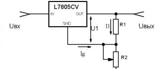
The turn-on delay angle of thyristors D1 and D4 is changed by potentiometer R1. Diodes D3 protect control (starting) values from negative voltage at a time when the voltage at the anodes of the thyristors is negative. To obtain wide limits of adjustment a (0 - Pi), RC circuits are used. In the rectifier (Fig. 2), the thyristor and the triggering circuit operate in both positive and negative half-cycles, the discharge time of the capacitors is reduced, which leads to a decrease in the range of angle a and, accordingly, to a decrease in the limits of voltage regulation at the load. To eliminate this phenomenon, diode D3 is turned on.
It is advisable to select thyristors for the rectifier (Fig. 1) with a similar resistance value of the control electrode - cathode section. If it is not possible to select identical thyristors, then the circuit can be balanced using additional resistance. To do this, turn on the equivalent load and change the resistance value of potentiometer R1 to set the maximum current. By turning off the thyristor control circuits one by one, the current of each arm of the rectifier is measured. Variable resistance of 10 kom. is connected in parallel to the control electrode to the cathode of the thyristor through which the larger current flows. By changing the value of this resistance, the same current readings are achieved.
Taking into account the spread of thyristor parameters, it is necessary to adjust the resistances of resistors R1 and R2. First, R1 is taken slightly larger than calculated, and R2 is defined as the residual resistance of potentiometer R1, provided that its change does not lead to an increase in the load current. The maximum value of R1 is limited by the resistance at which the load current is zero.
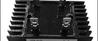
Structurally, thyristors must be placed on radiators with an area of 50 sq.cm (Fig. 1), 250 sq.cm - (Fig. 2). All options use a transformer assembled on a conventional USH35x55 core. PEV brand wire was used for winding. The primary winding contains 550 turns, wire diameter 0.55 mm. Secondary winding data: for the option in Fig. 1 - the number of turns is 2x60 with PEL wire with a diameter of 1.35 mm; for the option in Fig. 2 - the number of turns is 2x64 with PEL wire with a diameter of 1.35 mm.
I. SERYAKOV Y. RUCHKIN Radio No. 2, 1971
Source: shems.h1.ru
What is a thyristor and their types
Many have seen thyristors in the “Running Fire” garland; this is the simplest example of the device described and how it works. A silicon rectifier or thyristor is very similar to a transistor. This is a multilayer semiconductor device, the main material of which is silicon, most often in a plastic housing. Due to the fact that its operating principle is very similar to a rectifying diode (AC rectifier devices or dinistors), the designation on the diagrams is often the same - this is considered an analogue of a rectifier.
Photo - Running fire garland diagram
There are:
- ABB turn-off thyristors (GTO),
- standard SEMIKRON,
- powerful avalanche type TL-171,
- optocouplers (say, TO 142-12.5-600 or MTOTO 80 module),
- symmetrical TS-106-10,
- low frequency MTTs,
- triac BTA 16-600B or VT for washing machines,
- frequency TBC,
- foreign TPS 08,
- TYN 208.
But at the same time, IGBT or IGCT type transistors are used for high-voltage devices (furnaces, machine tools, and other industrial automation).
Photo – Thyristor
But, unlike a diode, which is a two-layer (PN) transistor (PNP, NPN), a thyristor consists of four layers (PNPN) and this semiconductor device contains three pn junctions. In this case, diode rectifiers become less efficient. This is well demonstrated by the thyristor control circuit, as well as any electricians’ reference book (for example, in the library you can read a book by the author Zamyatin for free).
A thyristor is a unidirectional AC converter, meaning it conducts current in one direction only, but unlike a diode, the device can be made to operate as an open circuit switch or as a DC rectifying diode. In other words, semiconductor thyristors can only operate in switching mode and cannot be used as amplification devices. The key on the thyristor is not capable of moving to the closed position on its own.
The silicon controlled rectifier is one of several power semiconductor devices, along with triacs, AC diodes, and unijunction transistors, that can switch from one mode to another very quickly. Such a thyristor is called high-speed. Of course, the class of the device plays a big role here.
Application of thyristor
The purpose of thyristors can be very different, for example, a homemade welding inverter using thyristors, a charger for a car (thyristor in the power supply) and even a generator are very popular. Due to the fact that the device itself can pass both low-frequency and high-frequency loads, it can also be used for a transformer for welding machines (their bridge uses exactly these parts). To control the operation of the part in this case, a voltage regulator on the thyristor is needed.
Specifications
Let's consider the technical parameters of the KU 202e series thyristor. This series presents domestic low-power devices, the main use of which is limited to household appliances: it is used to operate electric furnaces, heaters, etc.
The drawing below shows the pinout and main parts of the thyristor.
Photo - ku 202
- Set reverse on-state voltage (max) 100 V
- Closed voltage 100 V
- Pulse in open position - 30 A
- Repeated pulse in open position 10 A
- Average voltage =0.2 V
- Set current in open position
Photo - thyristor Ku202n
The price of a thyristor depends on its brand and characteristics. We recommend buying domestic devices - they are more durable and affordable. In spontaneous markets you can buy a high-quality, powerful converter for up to a hundred rubles.
Three-phase thyristor voltage rectifier: examples of practical application
The three-phase thyristor rectifier is designed to convert the three-phase alternating voltage of the network into a constant regulated one. Let's consider examples of the practical application of a controlled thyristor converter.
The three-phase thyristor rectifier is designed to convert three-phase alternating mains voltage into adjustable constant voltage. The rectifier is one of the most common and classic power electronics products. We invite the reader to familiarize themselves with its internal structure and application options.
The general structure of a typical rectifier system is shown in Figure 1:
Figure 1. Three-phase thyristor current (voltage) rectifier
Three-phase alternating voltage is supplied to the primary winding of the network transformer TV through the network choke L. The voltage from the secondary winding is supplied to the controlled thyristor rectifier VS, assembled using a Larionov bridge circuit. The output voltage of the rectifier contains harmonics and filtering, for the suppression of which an L-shaped inductive-capacitive filter F is designed. In some cases, grounding of the negative wire (PE wire) is required.
Let's look at practical examples of using this device.
Example 1. Power distribution across three phases when supplying a single-phase load
Quite often there is a case when the heating element of an electric furnace is single-phase. With a large number of such furnaces in an enterprise and powering them with single-phase voltage, severe phase imbalances occur, which adversely affects other consumers and reduces the throughput of the electrical network. One solution could be to use a rectifier - when powering the load through a controlled rectifier, the power is evenly distributed across all three phases:
Figure 2. Powering a single-phase load from a three-phase rectifier
Example 2: DC Power Supply
The voltage rectifier can be used as a regulated high-power DC power supply. Such a source can be used for various applications: powering galvanic baths, charging batteries (thyristor charger), powering devices and substation automation with operational current (operating current cabinet SHOT). If it is necessary to implement a DC power system with protective grounding, galvanic isolation through a transformer is required.
Figure 3. DC Power Supply
Example 3: DC Motor Control
The classic application of a three-phase rectifier is to control the speed of a DC motor (DC):
Figure 4. DC Motor Speed Controller
To do this, you need two rectifiers: one powers the field winding, the second powers the armature winding. Currently, the DC electric drive is being intensively replaced by the AC variable frequency drive (VFD); However, for a number of reasons, DC motors are now widely used in industry and transport.
Figure 5. Three-phase thyristor controlled AC rectifier TVN
The Russian manufacturer of adjustable rectifiers is, which serially and on order produces a three-phase thyristor voltage rectifier TVN. The company's products are distinguished by a wide range of service functions, the presence of a complex of protections, stability, and reasonable weight and dimensions. The price of a thyristor rectifier is kept at a level affordable for most potential customers. Modern materials and components are used in production, for example, thyristor modules from Semikron, the world's leading manufacturer of power semiconductor devices. All products undergo careful control at all stages.
Basic technical data:
- rated output current 40, 80, 125, 160, 200, 250, 315, 400, 500, 630 A;
- output voltage – adjustable or stabilized (according to order);
- control system – microprocessor;
- output voltage and current stabilization modes;
- protection against short circuit, overload, overheating, loss or “sticking” of phases;
- data indication on a liquid crystal display;
- programming parameters from the push-button control panel;
- wide choice of control signals;
- degree of protection IP41 with the possibility of increasing to IP54;
- Upon request, additional equipment includes a smoothing choke, a mains filter, smoothing capacitors, and an analog output board.
Based on materials
Description of design and principle of operation
The thyristor consists of three parts: “Anode”, “Cathode” and “Input”, consisting of three pn junctions that can switch between “ON” and “OFF” positions at very high speed. But at the same time, it can also be switched from the “ON” position for different durations, i.e., over several half-cycles, in order to deliver a certain amount of energy to the load. The operation of a thyristor can be better explained by assuming that it will consist of two transistors connected to each other, like a pair of complementary regenerative switches.
The simplest microcircuits demonstrate two transistors, which are combined in such a way that the collector current, after the “Start” command, flows into the NPN transistor TR 2 channels directly into the PNP transistor TR 1. At this time, the current from TR 1 flows into the channels into the bases of TR 2. These two interconnected transistors are arranged such that the base-emitter receives current from the collector-emitter of the other transistor. This requires parallel placement.
Photo - Thyristor KU221IM
Despite all safety measures, the thyristor may involuntarily move from one position to another. This occurs due to a sharp jump in current, temperature changes and other various factors. Therefore, before you buy a thyristor KU202N, T122 25, T 160, T 10 10, you need to not only check it with a tester (ring), but also familiarize yourself with the operating parameters.
Typical thyristor current-voltage characteristics
To start discussing this complex topic, look at the diagram of the current-voltage characteristics of a thyristor:
Photo - characteristics of the thyristor current-voltage characteristic
- The segment between 0 and (Vо,IL) fully corresponds to direct locking of the device;
- In the Vvo section, the thyristor is in the “ON” position;
- The segment between the zones (Vvo, IL) and (Vн,In) is the transition position in the on state of the thyristor. It is in this area that the so-called dinistor effect occurs;
- In turn, points (Vн,In) show on the graph the direct opening of the device;
- Points 0 and Vbr are the section where the thyristor is turned off;
- This is followed by the segment Vbr - it indicates the reverse breakdown mode.
Naturally, modern high-frequency radio components in a circuit can affect the current-voltage characteristics in an insignificant way (coolers, resistors, relays). Also, symmetrical photothyristors, SMD zener diodes, optothyristors, triode, optocouplers, optoelectronic and other modules may have different current-voltage characteristics.
Photo - current-voltage characteristic of a thyristor
In addition, we draw your attention to the fact that in this case, device protection is carried out at the load input.