According to the technical characteristics, the lm7812 microcircuit is a linear stabilizer of positive polarity with a simple switching circuit. Its body has only three external terminals, so many people confuse it with a regular transistor, but in fact it is a more complex semiconductor device.
Belongs to the 78xx series of integrated circuits, widely known throughout the world. The symbols "lm" at the beginning of the marking currently indicate its main manufacturer - Texas Instruments. The first two digits “78” indicate positive polarity, and the following “12” indicate the supported stabilization voltage - 12V.
Stabilizers of the LM family
In our article we will look at voltage stabilizers of the LM78XX family. The 78XX series is produced in metal cases TO-3 (left) and in plastic cases TO-220 (right). Such stabilizers have three terminals: input, ground (common) and output.
Instead of “XX”, manufacturers indicate the stabilization voltage that this stabilizer will give us. For example, the 7805 stabilizer will produce 5 Volts at the output, 7812 will produce 12 Volts, and 7815 will produce 15 Volts. Everything is very simple.
How to check the electrical stabilizer?
To troubleshoot the device, you need to do the following:
- Preliminary check. It can be carried out without special devices. To do this, you will need two table lamps of the same power, an electric stove or other powerful consumer, and a power extension cord with several sockets. We connect a stabilizer, one light bulb and an electric stove to the extension cord. We power the second light bulb from the stabilizer. Turn on the tile. If the stabilizer works correctly, then the light of the lamp connected to it will not change, but the light of the lamp connected to the extension cord will decrease.
- Disassembling the equipment, thoroughly removing all contaminants, cleaning the contact pads to a metallic shine.
- Inspection of the stabilizer, identification of electronic components with traces of exposure to high temperature. Overheated resistors look charred, and blackening and cracks may appear on the transistors. You also need to pay attention to swollen capacitors. Another symptom of overheating is a change in the shade of the textolite board.
- Ringing of power switches and other components.
Connection diagram
And here is the connection diagram for such stabilizers. This circuit is suitable for all stabilizers of the 78XX family.
In the diagram we see two capacitors that are sealed on each side. These are the minimum values of capacitors; it is possible, and even desirable, to supply a higher value. This is required to reduce ripple at both the input and output. For those who have forgotten what ripple is, you can look at the article on how to obtain a constant voltage from an alternating voltage.
L7812cv current stabilizer circuit
_________________ My name is Denis
JLCPCB, only $2 per PCB prototype! Any colour!
Register and receive two coupons for $5 each: https://jlcpcb.com/cwc
PCB Assembly from $30 + FREE Shipping Worldwide + Stencil
_________________ Wisdom (experience and endurance) comes with age. All your troubles and problems are due to lack of knowledge. A smart person will learn from a fool, but Albert Einstein will not help a fool and the GDP will not save him. and the Ministry of Emergency Situations is late and yet now Fools and Tolerants die on Fridays!
Characteristics of stabilizers
What voltage should be supplied for the stabilizer to work as it should? To do this, we are looking for a datasheet for stabilizers and studying it carefully. We are interested in these characteristics:
Output voltage - output voltage
Input voltage - input voltage
We are looking for our 7805. It gives us an output voltage of 5 Volts. Manufacturers noted a voltage of 10 volts as the desired input voltage. But it happens that the output stabilized voltage is sometimes either slightly underestimated or slightly overestimated.
For electronic trinkets, fractions of volts are not felt, but for precision (accurate) equipment it is better to assemble your own circuits. Here we see that the 7805 stabilizer can give us one of the voltages in the range of 4.75 - 5.25 Volts, but the conditions must be met that the output current in the load will not exceed 1 Ampere. An unstabilized DC voltage can “fluctuate” in the range from 7.5 to 20 Volts, while the output will always be 5 Volts.
The power dissipation on the stabilizer can reach up to 15 Watts - this is a decent value for such a small radio component. Therefore, if the load at the output of such a stabilizer consumes a decent current, I think it’s worth thinking about cooling the stabilizer. To do this, it must be placed on the radiator through KPT paste. The greater the current at the output of the stabilizer, the larger the radiator should be. It would be generally ideal if the radiator was also blown by a fan.
L7812cv current stabilizer circuit
L7805CV / L7806CV / L7809CV / L7810CV / L7812CV / L7815CV / L7824CV - positive polarity stabilizers with a maximum output current of 1.5A in a standard TO-220 package manufactured by ST microelectronics.
The L7808CV, L7818CV, L7820CV and L7824CV stabilizers are available for bulk pre-order.
| Device type | L7805CV | L7806CV | L7809CV | L7810CV | L7812CV | L7815CV |
| Rated output voltage | +5V | +6V | +9V | +10V | +12V | +15V |
| Output voltage variation | +4.8..5.2V | +5.75..6.25V | +8.64..9.36V | +9.6..10.4V | +11.5..12.5V | +14.5..15.6V |
| Maximum output current | 1.5A (long term)* | |||||
| Maximum input voltage | +35V | |||||
| Output-input voltage (dropout) | 2V (typ.) | |||||
| Maximum power dissipation without heat sink | 1.5W | |||||
| Maximum power dissipation with heat sink (+25°C) | 15W | |||||
| Crystal Temperature Range | 0..+150°C | |||||
| Frame | TO-220 | |||||
The minimum values of the input and output capacitance of the capacitors required for stable operation of the stabilizers are indicated. In practical circuits, it is recommended to use values in the tens to thousands of microfarads to minimize output voltage ripple.
Stabilizer operation in practice
Let's look at our ward, namely the LM7805 stabilizer. As you already understand, at the output we should get 5 Volts of stabilized voltage.
Let's assemble it according to the diagram
We take our Breadboard and quickly assemble the connection diagram suggested above. The two yellow ones are capacitors, although it is not necessary to install them.
So, wires 1,2 - here we drive the unstabilized input DC voltage, remove 5 Volts from wires 3 and 2.
On the Power Supply we set the voltage in the range of 7.5 Volts and up to 20 Volts. In this case, I set the voltage to 8.52 Volts.
And what did we get at the output of this stabilizer? 5.04 Volts! This is the value we will get at the output of this stabilizer if we supply voltage in the range from 7.5 to 20 Volts. Works great!
Let's check one more of our stabilizers. I think you have already guessed how many volts it is.
We assemble it according to the diagram above and measure the input voltage. According to the datasheet, you can supply it with an input voltage from 14.5 to 27 Volts. We set 15 Volts with kopecks.
And here is the output voltage. Damn, some 0.3 Volts is not enough for 12 Volts. For radio equipment operating on 12 Volts this is not critical.
Voltage stabilizer microcircuits. The main mistake when using it.
This article describes how to correctly use the characteristics of linear voltage stabilizer microcircuits 7805,7808,7812 and similar KR142EN5,8,12.
The most common microcircuits that are used in power supplies for various devices. They have become so widespread due to the extremely simple connection scheme and fairly good parameters when used correctly. The basic connection diagram looks like this:
Voltage stabilizer microcircuits are available in different capacities:
Designations on the chip:
The housings of the microcircuits are also different depending on the power:
voltage stabilizer microcircuits produce output voltages from 5V to 24V:
In this case, the input voltages and temperature characteristics are as follows:
The characteristics for medium power microcircuits are as follows:
And for low-power microcircuits, respectively:
In this case, the series of output voltages for low-power microcircuits looks like this:
3.3; 5; 6; 8; 9; 10; 12; 15; 18; 24 Volt
What parameters for voltage stabilizer microcircuits are mostly given on the Internet? Let's look at the most common cases using a specific example:
For loads over 14 W, it is advisable to install the stabilizer on an aluminum heatsink; the greater the load, the greater the required cooling surface area. Produced mainly in the TO-220 housing Maximum load current: 1.5 V Permissible input voltage: 35 V Output voltage: 5 V Number of regulators in the housing: 1 Current consumption: 6 mA Accuracy: 4% Operating temperature range: 0 C … +140 C Domestic analogue of KR142EN5A
It would seem that everything is written out from the documentation (DataSheet). How does a person perceive such information? The highest voltage is 35 V, okay, I won’t take the limit, I’ll take 30 V. The maximum load current is 1.5 A. I won’t take the limit value, I’ll take 1 A. I assemble a circuit using these data, but after working for some time it breaks down. Some people don’t understand and blame the quality of the microcircuits. After all, I didn’t force the microcircuit to work at the maximum voltage and current values, but it failed.
But the whole point is that many people forget about the main parameter, which is indicated in the documentation, but somehow does not attract attention because voltage and current. This is the maximum power that the stabilizer chip can dissipate. As a rule, it is indicated directly. For example, for powerful chips this is 1.5 W without a radiator and 15 W with a radiator.
What happens with a selected current of 1A and a maximum voltage of 30V, for example, for a microcircuit with an output voltage of 5V. Since the stabilizer is linear, the chip will drop 30 – 5 = 25 V. At a current of 1A, the power dissipated on the chip will be 1A × 25V = 25W. This is almost twice the permissible power with a radiator. This is where she breaks down. It turns out that with an input voltage of 30 V, the maximum current in the load cannot exceed 15 W: 25 V = 0.6 A.
In the tables given above in this article, for medium-power microcircuits without a radiator, the maximum power is 1.2 W, and with a radiator, 12 W. For low-power microcircuits, the installation of radiators is not provided and the maximum power dissipation is 0.625 W.
It is power that is decisive when choosing the limit values of current and voltage.
For clarity, the limit values of power, voltage and current for voltage stabilizer microcircuits of different powers are summarized in one table:
The minimum voltage drop on the chip is 2.5V.
If you follow this rule, the microcircuits will work reliably.
The article material is duplicated on video:
How to make a power supply for 5, 9.12 Volts
How to make a simple and highly stable power supply for 5, 9 or even 12 Volts? Yes, very simple. To do this, you need to read this article and install a stabilizer on the radiator at the output! That's all! The circuit will be approximately like this for a 5 Volt power supply:
Two electrolytic capacitors to eliminate ripple and a highly stable 5 volt power supply at your service! To get a power supply for a higher voltage, we also need to get a higher voltage at the output of the transformer. Aim for the voltage on capacitor C1 to be no less than in the datasheet for the stabilizer being described.
To ensure that the voltage stabilizer does not overheat, apply the minimum voltage specified in the datasheet to the input. For example, for the 7805 stabilizer this voltage is 7.5 Volts, and for the 7812 stabilizer the desired input voltage can be considered a voltage of 14.5 Volts. This is due to the fact that the voltage difference, and therefore the power, the stabilizer will dissipate on itself.
As you remember, the power formula is P=IU, where U is voltage and I is current. Consequently, the higher the input voltage of the stabilizer, the greater the power consumed by it. And excess power means heating. As a result of heating, such a stabilizer may overheat and enter a protection state, in which further operation of the stabilizer stops or even burn out.
Kren 7812 connection diagram
The popular domestic KRENxx line has been replaced by an imported stabilizer based on the L7812 microcircuit (or simply 7812). Its switching circuit has not changed, and the characteristics have improved slightly. For more details, see the datasheet for it.
Technical parameters of L7812
- TO220 housing
- Rated output current, A 1.2
- Maximum input voltage, V 40
- Output voltage, V 12
The pinout is shown in the figure below. There you can see the differences in the connection of the L7812 from the L7912 , which works with a common plus.
With all its advantages, this voltage stabilizer has a maximum load current of 1.5A, which often does not allow it to be used to power various types of current-intensive devices, for example a car radio. However, the good characteristics of this stabilizer and the presence of protection made it popular. The circuit for increasing the maximum current described in the datasheet uses an additional powerful PNP transistor.
The circuit I described works with NPN transistors, where KT803/KT805/KT808, which can be found everywhere, will fit perfectly. Therefore, if you live in a village and you cannot find powerful PNP transistors, as in the 70-80s of the last century, feel free to collect them.
Diode D1 compensates for the 0.6V drop across power transistor Q1, connected in an emitter follower circuit. 1N4007 and similar ones will be used as D1. As Q1 KT803, KT805, KT808, KT819 in metal cases. You can leave everything like this, or you can do it like this:
How to choose a radiator? The power released by the power transistor is approximately equal to:
P=(Uinput-Uoutput)*Iload
Then approximately every watt of heat must be dissipated over 10cm2 of cooling surface.
The L7812 stabilizer itself is installed on the same radiator or on a separate one, with an area approximately 30 times smaller than that of Q1.
What should I choose for the maximum current of the resulting stabilizer? It all depends on the current you need. This must be such a current that would not go beyond the permissible limits for Q1. Let's assume a maximum current of 3A. The voltage drop across resistor R1 is 0.6V. Then:
The power it dissipates: P=(Upad^2)/R1=1.8W, with a technological margin of 50% you will need a 4W resistor.
This stabilizer is housed in a TO-220 housing, which has three terminals. It is capable of stabilizing a voltage of 12 volts, which makes it possible to use it in various electronic devices.
- Output type – permanent.
- Output current – 1 ampere.
- The lowest operating temperature is 0 degrees.
- The highest operating temperature is 125 degrees.
- Number of pins – 3.
- Rated voltage is 12 volts.
- The lowest input voltage is 14.5 volts.
- The highest input voltage is 27 volts.
- Housing type – TO – 220 AB.
Most often, such stabilizers are used in one part of the circuit when there is no point in creating an entire power supply for devices. The 7812 regulator uses internal current overheating protection. This makes the unit at its base very reliable. With good cooling by the radiator, the 7812 stabilization device is capable of delivering a current of 1 ampere. The highest input voltage should be no lower than 14.8 V and no higher than 35 V.
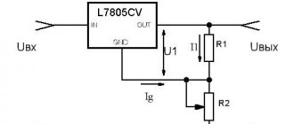
Such stabilizers were created for sources of a certain constant voltage of 12 V; using additional elements, these devices can be converted into stabilized current sources with the ability to adjust.
The stabilizer operation scheme is suitable for all microcircuits of this type:
Three-terminal stabilizers
For many non-critical applications, a conventional 3-pin regulator will be the optimal choice. It has only 3 external outputs. It is factory set to a fixed voltage. The 7800 series are representatives of stabilizers of this type. The last two digits indicate the voltage. We have already talked about one of this series earlier (7805)
The figure shows how easy it is to make a stabilizer, for example, at 5 volts, using one circuit. A capacitance connected in parallel with the output optimizes transition processes and keeps the output resistance low at higher frequencies. If the device is located far from the filter, then an auxiliary input capacitor must be used. The 7800 series is produced in metal and plastic cases.
lm7812 stabilizer 12 V
The 7812 voltage stabilizer changes the voltage up to 20 V to 12 V. This device was often used to create a stable operating voltage for low voltage devices: audio amplifiers, microcontrollers, lighting lamps.
An unstable voltage value, and even a variable value, can be connected to the input stage. LM 7812 is a stabilizer included in the 78xx series of microcircuits. They differ only in the output voltage, other parameters remain the same.
For better heat dissipation, a cooling radiator is attached to the stabilizer body. It can be removed from old devices from the board. Instead of a radiator, you can use tin from cans, cutting it into strips and drilling holes in them for mounting with a screw.
A voltage stabilizer is the most important radio element of modern radio-electronic devices. It provides a constant voltage at the output of the circuit, which is almost independent of the load.
Stabilizers of the LM family
In our article we will look at voltage stabilizers of the LM78XX family. The 78XX series is produced in metal cases TO-3 (left) and in plastic cases TO-220 (right). Such stabilizers have three terminals: input, ground (common) and output.
Instead of “XX”, manufacturers indicate the stabilization voltage that this stabilizer will give us. For example, a 7805 stabilizer will produce 5 Volts at the output, 7812 will produce 12 Volts, and 7815 will produce 15 Volts. Everything is very simple.
Connection diagram
And here is the connection diagram for such stabilizers. This circuit is suitable for all stabilizers of the 78XX family.
In the diagram we see two capacitors that are sealed on each side. These are the minimum values of capacitors; it is possible, and even desirable, to supply a higher value. This is required to reduce ripple at both the input and output. For those who have forgotten what ripple is, you can look at the article on how to obtain a constant voltage from an alternating voltage.
Characteristics of LM stabilizers
What voltage should be supplied for the stabilizer to work as it should? To do this, we are looking for a datasheet for stabilizers and studying it carefully. We are interested in these characteristics:
Output voltage – output voltage
Input voltage – input voltage
We are looking for our 7805. It gives us an output voltage of 5 Volts. Manufacturers noted a voltage of 10 volts as the desired input voltage. But it happens that the output stabilized voltage is sometimes either slightly underestimated or slightly overestimated.
For electronic trinkets, fractions of volts are not felt, but for precision (accurate) equipment it is better to assemble your own circuits. Here we see that the 7805 stabilizer can give us one of the voltages in the range of 4.75 - 5.25 Volts, but the conditions must be met that the output current in the load will not exceed 1 Ampere. An unstabilized DC voltage can “fluctuate” in the range from 7.5 to 20 Volts, while the output will always be 5 Volts.
The power dissipation on the stabilizer can reach up to 15 Watts - this is a decent value for such a small radio component. Therefore, if the load at the output of such a stabilizer consumes a decent current, I think it’s worth thinking about cooling the stabilizer. To do this, it must be placed on the radiator through KPT paste. The greater the current at the output of the stabilizer, the larger the radiator should be. It would be generally ideal if the radiator was also blown by a fan.
LM work in practice
Let's look at our ward, namely the LM7805 stabilizer. As you already understand, at the output we should get 5 Volts of stabilized voltage.
Let's assemble it according to the diagram
We take our Breadboard and quickly assemble the connection diagram suggested above. The two yellow ones are capacitors, although it is not necessary to install them.
So, wires 1,2 - here we drive the unstabilized input DC voltage, remove 5 Volts from wires 3 and 2.
On the Power Supply we set the voltage in the range of 7.5 Volts and up to 20 Volts. In this case, I set the voltage to 8.52 Volts.
And what did we get at the output of this stabilizer? 5.04 Volts! This is the value we will get at the output of this stabilizer if we supply voltage in the range from 7.5 to 20 Volts. Works great!
Let's check one more of our stabilizers. I think you have already guessed how many volts it is.
We assemble it according to the diagram above and measure the input voltage. According to the datasheet, you can supply it with an input voltage from 14.5 to 27 Volts. We set 15 Volts with kopecks.
And here is the output voltage. Damn, some 0.3 Volts is not enough for 12 Volts. For radio equipment operating on 12 Volts this is not critical.
How to make a power supply for 5, 9.12 Volts?
How to make a simple and highly stable power supply for 5, 9 or even 12 Volts? Yes, very simple. To do this, you need to read this article and install a stabilizer on the radiator at the output! That's all! The circuit will be approximately like this for a 5 Volt power supply:
Two electrolytic capacitors to eliminate ripple and a highly stable 5 volt power supply at your service! To get a power supply for a higher voltage, we also need to get a higher voltage at the output of the transformer. Aim for the voltage on capacitor C1 to be no less than in the datasheet for the stabilizer being described.
To ensure that the voltage stabilizer does not overheat, apply the minimum voltage specified in the datasheet to the input. For example, for the 7805 stabilizer this voltage is 7.5 Volts, and for the 7812 stabilizer the desired input voltage can be considered a voltage of 14.5 Volts. This is due to the fact that the voltage difference, and therefore the power, the stabilizer will dissipate on itself.
As you remember, the power formula is P=IU, where U is voltage and I is current. Consequently, the higher the input voltage of the stabilizer, the greater the power consumed by it. And excess power is heating. As a result of heating, such a stabilizer may overheat and enter a protection state, in which further operation of the stabilizer stops or even burn out.
Conclusion
An increasing number of electronic devices require high-quality, stable power without any voltage surges. The failure of one or another electronic equipment module can lead to unexpected and not very pleasant consequences. Use the achievements of electronics to your health, and don’t worry about powering your electronic trinkets.
Buy a voltage stabilizer
You can buy these integrated stabilizers cheaply as a whole set on Aliexpress using this link. There are absolutely any values here, even for negative voltage.
lm7812 stabilizer 12 V
The 7812 voltage stabilizer changes the voltage up to 20 V to 12 V. This device was often used to create a stable operating voltage for low voltage devices: audio amplifiers, microcontrollers, lighting lamps.
An unstable voltage value, and even a variable value, can be connected to the input stage. LM 7812 is a stabilizer included in the 78xx series of microcircuits. They differ only in the output voltage, other parameters remain the same.
For better heat dissipation, a cooling radiator is attached to the stabilizer body. It can be removed from old devices from the board. Instead of a radiator, you can use tin from cans, cutting it into strips and drilling holes in them for mounting with a screw.
Source
Check procedure
The whole process comes down to how the diodes are tested. This is done with a conventional multimeter in resistance or diode testing mode. A working zener diode can conduct current in one direction, similar to a diode.
Let's consider an example of checking two zener diodes KS191U and D814A, one of them is faulty.
First we check the D814A diode. In this case, a zener diode, by analogy with a diode, passes current in one direction.
Now we check the KS191U zener diode. It is obviously faulty, since it cannot pass current at all.