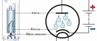
Power supplies for radio and electrical equipment almost always use rectifiers designed to convert alternating current to direct current. This is due to the fact that almost all electronic circuits and many other devices must be powered from DC sources. A rectifier can be any element with a nonlinear current-voltage characteristic, in other words, passing current differently in opposite directions. In modern devices, planar semiconductor diodes are usually used as such elements.
Planar semiconductor diodes
Along with good conductors and insulators, there are many substances that occupy an intermediate position in conductivity between these two classes. Such substances are called semiconductors. The resistance of a pure semiconductor decreases with increasing temperature, unlike metals, whose resistance increases under these conditions.
By adding a small amount of impurity to a pure semiconductor, its conductivity can be significantly changed. There are two classes of such impurities:
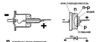
Figure 1. Planar diode: a. diode device, b. designation of a diode in electrical circuits, c. appearance of planar diodes of various powers.
The layer at the interface of p- and n-type semiconductors (pn junction) has one-way conductivity? conducts current well in one (forward) direction and very poorly in the opposite (reverse) direction. The structure of a planar diode is shown in Figure 1a. The basis ? a semiconductor plate (germanium) with a small amount of donor impurity (n-type), on which a piece of indium, which is an acceptor impurity, is placed.
Once heated, indium diffuses into the adjacent regions of the semiconductor, converting them into a p-type semiconductor. A pn junction occurs at the boundary of regions with two types of conductivity. The terminal connected to the p-type semiconductor is called the anode of the resulting diode, the opposite? its cathode. An image of a semiconductor diode on circuit diagrams is shown in Fig. 1b, appearance of planar diodes of various powers? in Fig. 1st century
History of invention
In 1873, the English scientist Frederick Guthrie developed the operating principle of directly heated vacuum tube diodes. A year later, in Germany, physicist Karl Ferdinand Braun suggested similar properties in solid-state materials and invented a point rectifier.
In early 1904, John Fleming created the first complete tube diode. He used copper oxide as the material for its manufacture. Diodes have begun to be widely used in radio frequency detectors. The study of semiconductors led to the invention of the crystal detector in 1906 by Greenleaf Witter Pickard.
In the mid-30s of the 20th century, the main research of physicists was aimed at studying the phenomena occurring at the metal-semiconductor contact boundary. Their result was the production of a silicon ingot with two types of conductivity. While studying it, in 1939, the American scientist Russell Ohl discovered a phenomenon later called the pn transition. He found that depending on the impurities existing at the interface of two semiconductors, the reducibility changes. In the early 50s, Bell Telephone Labs engineers developed planar diodes, and five years later, germanium-based diodes with a transition of less than 3 cm appeared in the USSR.
The inventor of the rectifier bridge circuit is considered to be an electrical engineer from Poland, Karol Pollak. Later, the results of Leo Graetz’s research were published in the journal Elektronische Zeitung, so in the literature one can also find another name for a diode bridge - circuit or Graetz bridge.
The simplest rectifier
Figure 2. Current characteristics in various circuits.
The current flowing in a conventional lighting network is variable. Its magnitude and direction change 50 times within one second. A graph of its voltage versus time is shown in Fig. 2a. Positive half-cycles are shown in red, ? negative.
Since the current value varies from zero to the maximum (amplitude) value, the concept of the effective value of current and voltage is introduced. For example, in a lighting network the effective voltage value is 220 V? in a heating device connected to this network, the same amount of heat is generated over equal periods of time as in the same device in a 220 V DC circuit.
But in fact, the network voltage changes in 0.02 s as follows:
- the first quarter of this time (period)? increases from 0 to 311 V,
- second quarter of the period? decreases from 311 V to 0,
- third quarter of the period? decreases from 0 to 311 V,
- last quarter of the period? increases from 311 V to 0.
In this case, 311 V? voltage amplitude Uо. The amplitude and effective (U) voltages are related to each other by the formula:
When a series-connected diode (VD) and load are connected to an alternating current circuit (Fig. 2b), current flows through it only during positive half-cycles (Fig. 2c). This happens due to the one-way conductivity of the diode. Is such a rectifier called half-wave? During one half of the period there is current in the circuit, during the second? absent.
The current flowing through the load in such a rectifier is not constant, but pulsating. You can turn it almost constant by connecting a filter capacitor Cf of a sufficiently large capacity in parallel with the load. During the first quarter of the period, the capacitor is charged to the amplitude value, and in the intervals between pulsations it is discharged to the load. The tension becomes almost constant. The greater the capacitor capacity, the stronger the smoothing effect.
Features of voltage types
A natural question arises about why alternating current is used in sockets, if the vast majority of electronic equipment is powered by direct current. The fact is that to power the nodes of this or that equipment, voltages of different magnitudes are required. A computer processor, for example, is powered by 3 V, and a mobile phone requires as much as 5 V to charge. A music center amplifier already needs about 25 V.
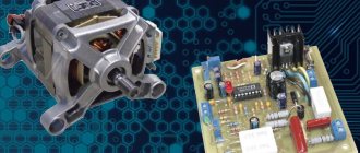
DC voltage is quite difficult to transform from one value to another, but alternating voltage is easy. For example, transformers are used for this. Some important power components, such as motors, still require AC power. Therefore, industrial generators that power household sockets produce it to a generally accepted value (for example, 220 V), and each device already receives from it what it needs on site.
Diode bridge circuit
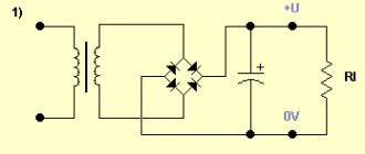
More advanced is the full-wave rectification circuit, when both positive and negative half-cycles are used. There are several varieties of such schemes, but the most commonly used is pavement. The diode bridge circuit is shown in Fig. 3c. The red line on it shows how current flows through the load during positive times, and the blue line? negative half-cycles.
Figure 4. 12 volt rectifier circuit using a diode bridge.
In both the first and second half of the period, the current through the load flows in the same direction (Fig. 3b). The amount of pulsation within one second is not 50, as with half-wave rectification, but 100. Accordingly, with the same filter capacitor capacity, the smoothing effect will be more pronounced.
As you can see, to build a diode bridge you need 4 diodes? VD1-VD4. Previously, diode bridges on circuit diagrams were depicted exactly as in Fig. 3c. The image shown in Fig. 1 is now generally accepted. 3g. Although there is only one picture of a diode, it should not be forgotten that the bridge consists of four diodes.
The bridge circuit is most often assembled from individual diodes, but sometimes monolithic diode assemblies are also used. They are easier to mount on the board, but if one arm of the bridge fails, the entire assembly is replaced. The diodes from which the bridge is mounted are selected based on the amount of current flowing through them and the amount of permissible reverse voltage. This data can be obtained from diode instructions or reference books.
The complete circuit of a 12 volt rectifier using a diode bridge is shown in Fig. 4. T1? step-down transformer, the secondary winding of which provides a voltage of 10-12 V. Fuse FU1? This is a useful detail from a safety point of view and should not be neglected. The brand of diodes VD1-VD4, as already mentioned, is determined by the amount of current that will be consumed from the rectifier. Capacitor C1? electrolytic, with a capacity of 1000.0 μF or higher for a voltage of at least 16 V.
Output voltage? fixed, its value depends on the load. The higher the current, the lower the voltage. To obtain a regulated and stable output voltage, a more complex circuit is required. Obtain the regulated voltage from the circuit shown in Fig. 4 can be done in two ways:
It is hoped that the descriptions and diagrams given above will provide practical assistance in assembling a simple rectifier for practical needs.
There is an inconsistency in electrical engineering. On the one hand, it is more convenient to transmit energy over long distances if it is in the form of alternating voltage. On the other hand, direct current is required to power smartphones, LEDs in light bulbs, circuit boards in TVs and similar household appliances. This problem is successfully solved by a family of radio components such as rectifier diodes.
Electricity rectification
Until the end of the 19th century, converting alternating voltage to direct voltage was a problem. With the invention of the diode - first vacuum, and later semiconductor - the situation changed radically. Thanks to its unique properties, the diode perfectly distinguishes polarity and makes it easy to sort currents in the desired direction. At first, separate diodes were used for these purposes, later diode bridges appeared, providing high quality rectification.
Single diode rectifier
A diode conducts current in only one direction, which is why it is called a semiconductor device. If you connect the plus of the voltage source to the cathode of the device, and the minus to the anode, the diode will behave like a regular conductor. If the polarity is changed, the device will close and turn into a dielectric. To answer the question of what this gives, you will have to assemble a simple circuit and again arm yourself with an oscilloscope.
The diagram shows the operation of a semiconductor diode in an alternating current circuit. The oscillogram on the left shows the picture at the output of the transformer - ordinary alternating current. After the diode, everything changes significantly - the negative half-wave of the alternating voltage disappears from the graph. The current has not yet become constant, but it is no longer alternating - there is no movement of the electric charge in the opposite direction. This type of current is usually called pulsating. They can't power electronics yet, but changes are evident. All that remains is to smooth out the pulse peaks. This is done using capacitors.
The diagram shows a half-wave rectifier with a smoothing capacitor. During a positive pulse, the voltage not only powers the load, but also charges the capacitor at the same time. When the pulse ends, the capacitor releases the accumulated energy, smoothing out voltage surges.
Full wave device
Despite the significant progress achieved in converting alternating current into direct current by previous experiments, the result is still far from ideal. The fact is that the frequency of alternating current is quite low (50 Hz), and hanging smoothing capacitors has its limitations. In order to significantly improve the shape of the output signal, you need to increase the frequency.
However, in sockets it is strictly fixed and does not depend on external factors. The negative half-wave of the voltage is cut off by a diode. Changing its polarity is not difficult at all - you just need to add a few diodes to assemble a bridge circuit. The figure shows a full-wave rectifier with four diodes, explaining how a diode bridge works:
When a positive half-wave appears, diodes VD2, VD3 will be turned on in the forward direction and will be open. VD1, VD2 - closed. The half-wave passes freely to the output of the rectifier. When the voltage changes polarity, the pairs of diodes will change places - VD1 and VD4 will open, VD2 and VD3 will close. The negative half-wave will also pass to the output, but will change polarity. The result will be the same pulsed unipolar voltage, but its frequency will double. All that remains is to add a smoothing capacitor and see what happens.
The full-wave rectifier with a smoothing capacitor in the image shows that the problem has been solved: the alternating voltage is converted to direct voltage. Of course, the consistency is not ideal - there are pulsations, but they can be dealt with using filters. In addition, any electronics allows for one or another amount of pulsation.
This circuit, consisting of four diodes, has become classic and is called a diode or rectifier bridge. There is a separate category of electronic devices - rectifier bridges. They consist of four diodes connected to each other in a suitable manner. As an example, you can look at the rectifier bridge KTS402G and its electrical circuit.
What are diodes
A diode is a semiconductor element based on a silicon crystal. Previously, these parts were also made of germanium, but over time this material was forced out due to its shortcomings. The electrical diode functions as a valve, i.e. it allows current to flow in one direction and blocks it in the other. Such capabilities are built into this part at the level of the atomic structure of its semiconductor crystals.
Read also: How to make a model of the moon from plasticine
One diode cannot obtain a full constant voltage from an alternating voltage. Therefore, in practice, more complex combinations of these elements are used. An assembly of 4 or 6 parts, combined according to a special circuit, forms a diode bridge. He is already quite capable of coping with full current rectification.
Interesting. Diodes have parasitic sensitivity to temperature and light. Transparent rectifiers in a glass case can be used as light sensors. Germanium diodes (approx. D9B) are suitable as a temperature-sensitive element. Actually, due to the strong dependence of the properties of these elements on temperature, they stopped producing them.
How to solder and connect
It is not difficult to study and know the circuits; the main difficulties arise when a beginner decides to solder a diode bridge with his own hands. To solder a rectifier from 4 Soviet copies of the KD202 type, use the illustration below.
To assemble a diode bridge from modern discrete diodes such as low-power 1n4007 (and others - they all look similar and differ only in size), take a close look at the following illustration.
But if you do not assemble it from separate parts, but use a ready-made bridge, then see below how to properly connect it to the circuit.
Also, beginners will be interested in watching a video on how to make a simple 12V power supply:
Single-phase and three-phase diode bridge
There are two main types of straightening assemblies:
- Single-phase bridge. Most often used in household electrical appliances. Has 4 outputs. Two of them are supplied with alternating voltage, i.e. phase (L) and zero (N). The permanent one is removed from the remaining two, i.e. plus (+) and minus (-).
- Three-phase bridge. It is found in powerful industrial installations and equipment powered by a 380 volt network. Three phases are supplied to its input (L1, L2, L3). The constant voltage is also removed from the output. Such bridges are distinguished by their large size and impressive currents that they are capable of passing through themselves.
Purpose and practical use
The scope of use of a bridge made of diodes is quite wide. These can be power supplies and control units. It is installed in all devices powered by a 220 volt industrial network. For example, TVs, receivers, chargers, dishwashers, LED lamps.
Cars cannot do without it either. After starting the engine, the generator starts working, producing alternating current. Since the on-board network is all powered by constant voltage, a rectifier bridge is installed through which rectified voltage is supplied. The same constant signal also recharges the battery.
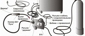
The rectifier device is used to operate the welding machine. True, it uses powerful devices that can withstand currents of more than 200 amperes. The use of diode assembly in devices provides a number of advantages compared to a simple diode. This straightening allows you to:
- increase the ripple frequency, which can then simply be smoothed out using an electrolytic capacitor;
- when working together with a transformer, get rid of the bias current, which makes it possible to more efficiently use the overall power of the converter;
- pass more power with less heat, thereby increasing efficiency.
But it is also worth noting the drawback due to which in some cases the bridge is not used. First of all, this is a double voltage drop, which is especially sensitive in low-voltage circuits. And also, when some of the diodes burn out, the device begins to operate in half-wave mode, which is why parasitic harmonics penetrate into the circuit, which can damage sensitive radioelements.
power unit
Not a single modern power supply can do without a rectifier. High-quality sources are manufactured using bridge rectifiers. The classic scheme consists of only three parts:
- A step-down transformer.
- Rectifier bridge.
- Filter.
A sinusoidal signal with an amplitude of 220 volts is supplied to the primary winding of the transformer. Due to the phenomenon of electromagnetic induction, an electromotive force is induced in its secondary winding and current begins to flow. Depending on the type of transformer, the voltage value is reduced by a certain value due to the transformation ratio.
An alternating signal with reduced amplitude appears between the terminals of the secondary winding. In accordance with the diode bridge connection diagram, this voltage is supplied to its input. Passing through the diode assembly, the alternating signal is converted into a pulsating one.
This form is often considered unacceptable, for example, for sound equipment or lighting sources. Therefore, a capacitor connected in parallel with the output of the rectifier is used for smoothing.
Three-phase rectifier
In production and in places where a three-phase network is used, a three-phase rectifier is used. It consists of six diodes, one pair for each phase. Using this type of device allows you to obtain a higher current value with low ripple. This, in turn, reduces the requirements for the output filter.
The most popular options for connecting three-phase rectifiers are the Mitkevich and Larionov circuits. In this case, not only six diodes can be used simultaneously, but also 12 or even 24. Three-phase bridges are used in diesel locomotives, electric vehicles, on drilling rigs, and in industrial gas and water purification plants.
Thus, the use of bridge rectifiers makes it possible to convert alternating current into direct current, which powers all electronic equipment. Making a diode bridge yourself is not difficult. At the same time, its use allows you to obtain not only a high-quality signal, but also increase the reliability of the device as a whole.
Operating principle of a diode bridge
You can understand how a bridge performs its task by understanding how a separate diode behaves. Initially there are only two wires with alternating voltage (L and N). It has the shape of a sinusoid (Fig. a). If you add one diode to the circuit, then it will transmit only the positive half-wave (Fig. b), if this component is deployed, then the negative component (Fig. c). This voltage will no longer be variable. However, it is not suitable for powering serious electrical appliances. There are moments in it when there is no current at all. The use of four diodes will allow you to obtain a constant voltage without any interruptions (Fig. d). Three-phase bridges are straightened using the same method. However, they do this with three sine waves at the same time.
Rectifier
The voltage obtained after the diode bridge has the shape of a sinusoid, in which the negative component is reflected relative to the time axis. In simple terms, it is shaped like hills and is called pulsating. This voltage is positive. Does not contain moments when current does not flow. But it is still unstable. For example, at point “a” it is early 0 volts, and at “b” it has a maximum value. This rectifier cannot be considered complete.
To solve this problem, a smoothing electrolytic capacitor is required. On the board it is usually located in the same place as the diode assembly. The capacitance accumulates energy at those moments when it has peak values (point b), and releases it at moments of dips (a). The output is a straight line - full-fledged direct current, suitable for powering subsequent electronic components, processors, microcircuits, etc.
Disadvantages of a full bridge
A full-fledged full-wave bridge has disadvantages:
- The current is forced to flow not through one diode, but through two at once, connected in series. Therefore, the voltage drop across the rectifier element doubles. For low-power bridges on silicon diodes it can reach 2 volts. In powerful rectifiers - about 10 V. Hence, significant power losses on the rectifying element and its increased heating.
- If one or four diodes fail, the bridge continues to operate. This defect may not be noticeable without special measurements. However, it creates the risk of more serious damage to the device, which is powered through a faulty bridge.
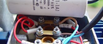
Design
The circuit of any rectifier bridge includes diodes. They can be separately soldered onto a printed circuit board or located in the same housing. Regarding the size, rectifiers are miniature, for example, imported MB6S or Soviet KTs405A. The latter are popularly called “ka-tseshki” or “chocolates”.
There are samples with impressive dimensions. For example, a three-phase rectifier bridge made in China. The device is designed for currents of hundreds of amperes, therefore it has screw fastening for power wires and a flat metal heat-conducting surface with holes for fixing on the cooling radiator.
Rectifier markings
There are no generally accepted rules according to which manufacturers label their diode bridges. Everyone has the right to name their product as they see fit, i.e. according to its own nomenclature.
However, most of these parts have similar features that help visually determine the purpose of their pins. In the photo of a three-phase bridge (see above), the alternating current symbol is highlighted separately - a wavy line. It indicates that a sinusoidal input voltage is connected to this pin. Also on some bridge models, the input terminals are marked with the letters AC (Alternative Current), indicating alternating current. In this case, the output contacts from which direct current is removed are indicated by the symbols DC (Direct Current) or the traditional “+” and “-”. Additionally, on some rectifiers, one of the corners is “filed” on the plus side. An extended pin can also indicate “+”. This type of marking is common to many electronic components and is called a key.
DIY diode bridge
To assemble the rectifier yourself, you will need 4 diodes of the same type. At the same time, they must be suitable in terms of reverse voltage, maximum current and operating frequency. Connections must be made in accordance with the diagram below. A positive voltage is removed between the two cathodes and a negative voltage between the anodes. An alternating voltage source is connected to the points at which opposite terminals of the diodes are connected. The entire circuit can be soldered by surface mounting in a couple of minutes, or you can work hard and make it in the form of a small printed circuit board.
Additional Information. The reverse voltages of diodes connected in a series circuit are added to each other.
12 Volts from 24 or other higher DC voltage
In addition, there are situations when, instead of a mains voltage of 220 Volts, you have a constant voltage of a higher rating, for example, 24 Volts. A similar situation can arise when motorists want to replace their car battery with a more powerful one from a truck or bus.
For this purpose, a stabilizing element based on the same transistor from which the LED strip is connected can be used.
Example of a 12V from 24V circuit
This is a fairly simple circuit in which the output current will be limited by the characteristics of the transistor. The disadvantage of this option is a slight reduction in voltage if the maximum current for the converter is exceeded. Therefore, in case of an unacceptable result, instead of a transistor, you can use various stabilizers - linear or pulsed. The stabilizer is a more complex device, but the connection diagram will be practically no different, since they are sold as a single unit.
Selecting a build type
For each task there is its own optimal version of the rectifier diode assembly. All of them can be divided into 3 types:
- Rectifier with one diode. It is used in the simplest and cheapest circuits where there is no c.l. requirements for the quality of the output voltage, as, for example, in night lights.
- Dual diode. These parts look similar to transistors, because they are produced in the same packages. They also have 3 pins. Essentially, these are two diodes placed in one housing. One of the conclusions is average. It can be the common cathode or the anode of the internal diodes.
- Full diode bridge. 4 parts in one case. Suitable for devices with high currents. It is mainly used on the inputs and outputs of various power supplies and chargers.
Additional Information. Rectifiers are also used in cars. They are needed to convert the alternating voltage coming from the generator to direct voltage. This, in turn, is necessary to charge the battery. A conventional gas generator produces alternating current.
Read also: Papercraft for beginners, paper modeling, three-dimensional sculptures and simple paper figures for children
Transformers (with or without rectifier)
The heart of a transformer is the core. It is assembled from transformer steel plates, which are quite problematic to make by hand. By hook or by crook, the source material is extracted at factories, construction teams, and scrap metal collection points. The resulting structure (usually in the form of a rectangle) must have a cross-section of no less than 55 cm². This is a rather heavy structure, especially after laying the windings.
During assembly, it is imperative to provide an adjusting screw, with which you can move the secondary winding relative to the stationary primary.
In order not to go into the complexity of calculating the cross-section of wires, we will take typical parameters:
- secondary current 100–150 A;
- open circuit voltage 60–65 volts;
- operating voltage when welding 18–25 volts;
- current on the primary winding is up to 25 A.
Based on this, the cross-section of the primary wire should be at least 5 mm²; if you do it with a margin, you can take a wire of 6–7 mm². The insulation must be heat-resistant and made from a material that does not support combustion.
The secondary winding is made of wire (or better yet, a copper busbar) with a cross-section of 30 mm². The insulation is rag. Don't let the thickness scare you, the number of turns on the secondary is small.
The number of turns of the primary winding is determined by a coefficient of 0.9–1 turns per volt (for our parameters).
The formula looks like this:
W(number of turns) = U(voltage) / coefficient.
That is, with a network voltage of 200–210 volts, it will be about 230–250 turns.
Accordingly, if the secondary voltage is 60–65 volts, the number of its turns will be 67–70.
From a technical point of view, the transformer is ready. For ease of use, it is recommended to make a small margin on the secondary winding, with several branches (at 65, 70, 80 turns). This will allow you to work confidently in places with low network voltage.
Hiding the unit in the housing or leaving it open is a matter of safety of use. A typical DIY welding transformer looks like this:
The optimal material for the case is 10–15 mm textolite.
Adding a rectifier
A homemade powerful welding transformer from a circuit design point of view is a regular power supply. Accordingly, the rectifier is designed as simply as in a network charger for a mobile phone. Only the element base will look several orders of magnitude more massive.
As a rule, a pair of capacitors are added to a simple diode bridge circuit to dampen rectified current pulses.
You can assemble a rectifier without them, but the smoother the current, the better the quality of the weld. To assemble the bridge itself, powerful diodes of the D161–250(320) type are used. Since a lot of heat is generated on the elements when loaded, it must be dissipated using radiators. The diodes are attached to them using a bolt connection and thermal paste.
Of course, the radiator fins must either be blown by a fan or protrude above the case. Otherwise, instead of cooling, they will heat the transformer.
Mini welding transformer
If you do not need to weld rails or channels from 4–5 mm steel, you can assemble a compact welder for soldering steel wire (making frames for homemade products) or welding thin sheet metal. To do this, you can take a ready-made transformer from a powerful household appliance (the ideal option is a microwave) and rewind the secondary winding. Wire cross-section 15–20 mm², power consumption no more than 2–3 kW.
The calculation of the circuit is carried out in the same way as for more powerful units. When assembling the rectifier, you can use less powerful diodes.
Micro welder
If the scope of application is limited to soldering copper wires (for example, when installing distribution boxes), you can limit yourself to a design the size of a pair of matchboxes.
Performed on transistor KT835 (837). The transformer is manufactured independently. In fact, it is a high-frequency boost converter.
We wind the transformer on a ferrite rod. Two primary windings: collector (20 turns 1 mm), base (5 turns 0.5 mm). Secondary (boost) winding - 500 turns of 0.15 wire.
We assemble the circuit, solder the resistor circuit according to the circuit (so that the transformer does not overheat at idle), the device is ready. Power supply from 12 to 24 volts, with the help of such a device you can weld wire harnesses, cut thin steel, and join metals up to 1 mm thick.
A thick sewing needle can be used as welding electrodes.
Checking elements
In most cases, it is not necessary to unsolder the bridge from the board for testing. It should be tested in the same way as a 4 pn junction with a diode bridge connection. This measurement is so common that its capability is implemented in any multimeter. The test device must be switched to diode continuity mode.
The forward voltage drop across a working rectifier diode is 500-700 mV. Otherwise, the device will display “1”. A burnt part most often shows “0” in both directions, i.e. short circuit. Less often, a complete breakage of the element occurs (also in both directions). All measurements should be repeated for each diode included in the bridge. Total 8 measurements, i.e. 4 in forward direction and 4 in reverse. If a Schottky diode is tested, then this parameter is 200-400 mV.
Self-production
Single-phase rectifier bridges are usually not scarce radio components, so they can be purchased and selected according to the required parameters in almost any radio store. But you don’t always have time for this, so you can assemble the required bridge with your own hands. To do this you will need to prepare:
- Four diodes with identical characteristics. In principle, you can take any, but you should understand that the general parameters of the bridge will be determined by the weakest element.
- Installation wire.
- Soldering iron.
- Tweezers.
- Flux and solder.
- Side cutters.
- Electrical circuit of a rectifier diode bridge.
After everything is prepared, at the first stage the diode leads are tinned. To do this, the legs of the radioelements are lubricated with flux, and tin is transferred to them using a heated soldering iron, forming a thin layer. At the next stage, the diodes are connected according to the diagram.
To do this, you need to know where the element’s cathode is and where the anode is. In the diagram, the anode corresponds to the top of the triangle, and the cathode corresponds to the base. On the element itself, only the anode is indicated. This can be a stripe, a dot, or a conventional graphic designation shifted to one of the terminals.
Then two elements are taken and the anode of one is connected to the cathode of the other. A similar action is repeated for the remaining elements. The result is a pair, each of which consists of two diodes. Next, the cathodes are soldered together, and the anodes are soldered together. After the diodes are connected to the solder points, the conductors are connected to form the terminals of the device. At the last stage, the design is checked using a multimeter.
Using the Schottky barrier
The use of a Schottky diode is justified in two cases. Firstly, when you need to rectify high-frequency current. The Schottky barrier is ideal for such a task, because it has a low junction capacitance and, accordingly, is fast-acting. Secondly, when it is necessary to rectify a large current of tens or hundreds of amperes. In this case, the part performs well due to the low voltage drop and low heat generation.
Diode bridges in the world of electronics play the role of a matching element. With their help, you can connect devices that require direct current to a network of alternating voltage convenient for transmission. There are a lot of such devices in everyday life; they are extremely important for a person’s comfortable life.
The main element used to create a rectifier unit is a diode. Its operation is based on the electron-hole transition (pn).
The generally accepted definition says: a pn junction is a region of space located at the boundary of the junction of two semiconductors of different types. In this space, an n-type to p-type transition is formed. The value of conductivity depends on the atomic structure of the material, namely on how tightly the atoms hold electrons. Atoms in semiconductors are arranged in a lattice, and electrons are bound to them by electrochemical forces. This material itself is a dielectric. It either conducts current poorly or does not conduct it at all. But if atoms of certain elements are added to the lattice (doping), the physical properties of such a material change radically.
Mixed atoms begin to form, depending on their nature, free electrons or holes. The resulting excess electrons form a negative charge, and the holes form a positive charge.
An excess charge of one sign causes carriers to repel each other, while an area with an opposite charge tends to attract them towards itself. An electron, moving, occupies a free space, a hole. At the same time, a hole also forms in its old place. As a result, two flows of charge movement are created: one main and the other reverse. A material with a negative charge uses electrons as majority carriers and is called an n-type semiconductor, while a material with a positive charge using holes is called a p-type semiconductor. In both types of semiconductors, minority charges generate a current opposite to the movement of the main charges.
In radio electronics, germanium and silicon are used from materials to create pn junctions. When crystals of these substances are doped, a semiconductor with different conductivity is formed. For example, the introduction of boron leads to the appearance of free holes and the formation of p-type conductivity. Adding phosphorus, on the other hand, will create electrons and the semiconductor will become n-type.
Diode operating principle
A diode is a semiconductor device that has low resistance to current in one direction and prevents it from flowing in the opposite direction. Physically, the diode consists of one pn junction. Structurally, it is an element containing two outputs. The terminal connected to the p-region is called the anode, and the terminal connected to the n-region is called the cathode.
When a diode operates, there are three states:
A forward potential is a signal when the positive pole of the power source is connected to the p-type region of the semiconductor, in other words, the polarity of the external voltage coincides with the polarity of the main carriers. With reverse potential, the negative pole is connected to the p-region and the positive pole to the n region.
There is a potential barrier in the area where the n- and p-type material joins. It is formed by a contact potential difference and is in a balanced state. The height of the barrier does not exceed tenths of a volt and prevents the movement of charge carriers deep into the material.
If direct voltage is connected to the device, then the magnitude of the potential barrier decreases and it practically does not resist the flow of current. Its value increases and depends only on the resistance of the p- and n-regions. When a reverse potential is applied, the barrier value increases, since electrons leave the n-region and holes leave the p-region. The layers become depleted and the barrier's resistance to the passage of current increases.
The main indicator of an element is the current-voltage characteristic. It shows the relationship between the potential applied to it and the current flowing through it. This characteristic is presented in the form of a graph, which indicates the forward and reverse current.
Physical processes
The operating principle of a diode bridge is based on the ability of a pn junction to pass current in only one direction. A pn junction is understood as a contact between two semiconductors with different types of conductivity. The boundary separating the regions is characterized by the width of the forbidden zone, which prevents the passage of charges. On one side there is the p region, in which the main carriers are holes (positive charge), and on the other, the n region, where the majority carriers are electrons (negative charge).
Being isolated from each other, in each region the elementary particles perform random thermal vibrations, due to which their released energy is compensated and the resulting current is zero. When these areas come into contact, diffusion currents arise due to the attraction of charges to each other. As a result, the particles collide and recombine (disappear). In the contact zone, carriers become depleted and their movement stops. A state of dynamic equilibrium is established.
When an electric field is applied to the pn junction, the picture changes. With forward bias, that is, when the positive pole of the power source is connected to the p region, and the negative pole to the n region, the main carriers are introduced into the region. Because of this, the bandgap width decreases, and particles freely begin to pass through the barrier, forming a current. If the polarity of the power source is changed, then even greater depletion of the layers will occur, as a result, the barrier will increase, and the current will not arise.
Thus, depending on the polarity of the signal applied to the junction, the band gap increases or decreases. If an alternating signal is applied to an element whose operation is based on a pn junction, then as a result, forward and reverse voltage will be alternately applied to it. Accordingly, it will delay part of the signal and transmit part of it.
If you take a measuring device that can show the waveform (oscilloscope), then at the output of the radio element you can see pulses, the duration of which is determined by the half-wave period. That is why the diode is called a rectifier, although the name pulse converter is more suitable for it. That is, a device that converts an alternating signal into a burst of pulses.
It’s also important to know: 3 nuances about operation
The homemade product differs somewhat in its method of operation from the factory version. This is explained by the fact that the purchased unit has built-in functions that help with operation. They are difficult to install on a device assembled at home, and therefore you will have to adhere to several rules during operation.
- A self-assembled charger will not turn off when the battery is fully charged. That is why it is necessary to periodically monitor the equipment and connect a multimeter to it to monitor the charge.
- You need to be very careful not to confuse “plus” and “minus”, otherwise the charger will burn out.
- The equipment must be turned off when connecting to the charger.
By following these simple rules, you will be able to properly recharge the battery and avoid unpleasant consequences.
Simple rectifier circuit
Sinusoidal voltage is a periodic signal that varies over time. From a mathematical point of view, it is described by a function in which the origin corresponds to time equal to zero. The signal consists of two half-waves. The half-wave located in the upper part of the coordinates relative to zero is called a positive half-cycle, and in the lower part - negative.
When an alternating voltage is applied to the diode through a load connected to its terminals, current begins to flow. This current is due to the fact that at the moment the positive half-cycle of the input signal arrives, the diode opens. In this case, a positive potential is applied to the anode and a negative potential to the cathode. When the wave changes to a negative half-cycle, the diode is turned off, as the polarity of the signal at its terminals changes.
Thus, it turns out that the diode, as it were, cuts off the negative half-wave, without passing it to the load, and a pulsating current of only one polarity appears on it. Depending on the frequency of the applied voltage, and for industrial networks it is 50 Hz, the distance between the pulses also changes. This type of current is called rectified, and the process itself is called half-wave rectification.
Read also: Homemade stand for angle grinders - detailed manufacturing instructions
By rectifying the signal using a single diode, you can power a load that does not have special requirements for voltage quality. For example, a filament. But if you power up, for example, a receiver, a low-frequency hum will appear, the source of which will be the gap that occurs between the pulses. To some extent, to get rid of the disadvantages of half-wave rectification, a capacitor connected in parallel with the load is used together with a diode. This capacitor will charge when pulses arrive and discharge when there are no pulses to the load. This means that the larger the capacitance value of the capacitor, the smoother the current across the load will be.
But the highest signal quality can be achieved if two half-waves are used simultaneously for rectification. The device that allows this to be realized is called a diode bridge, or in other words, a rectifier bridge.
A little theory about batteries
Any battery is a storage device for electrical energy. When voltage is applied to it, energy is stored due to chemical changes inside the battery. When a consumer is connected, the opposite process occurs: a reverse chemical change creates voltage at the terminals of the device, and current flows through the load. Thus, in order to get voltage from the battery, you first need to “put it down,” that is, charge the battery.
Almost any car has its own generator, which, when the engine is running, provides power to the on-board equipment and charges the battery, replenishing the energy spent on starting the engine. But in some cases (frequent or difficult engine starts, short trips, etc.) the battery energy does not have time to be restored, and the battery is gradually discharged. There is only one way out of this situation - charging with an external charger.
How to find out the battery status
To decide whether charging is necessary, you need to determine the state of the battery. The simplest option - “turns/does not turn” - is at the same time unsuccessful. If the battery “doesn’t turn”, for example, in the garage in the morning, then you won’t go anywhere at all. The “does not turn” condition is critical, and the consequences for the battery can be dire.
The optimal and reliable method for checking the condition of a battery is to measure the voltage on it with a conventional tester. At an air temperature of about 20 degrees, the dependence of the degree of charge on the voltage at the terminals of a battery disconnected from the load (!) is as follows:
- 12.6…12.7 V - fully charged;
- 12.3…12.4 V - 75%;
- 12.0…12.1 V - 50%;
- 11.8…11.9 V - 25%;
- 11.6…11.7 V - discharged;
- below 11.6 V - deep discharge.
It should be noted that the voltage of 10.6 volts is critical. If it drops below, the “car battery” (especially a maintenance-free one) will fail.
Correct charging
There are two methods of charging a car battery - constant voltage and constant current. Each has its own characteristics and disadvantages:
- Constant voltage charging - suitable for restoring the charge of not completely discharged batteries, the voltage at the terminals of which is not lower than 12.3 V. The process is as follows: a direct current source with a voltage of 14.2–14.7 V is connected to the battery terminals. The end of the process is monitored by the current consumption: when it drops to zero, charging is considered complete. The disadvantage of this method is that the initial charging current may be high; The more the battery is discharged, the higher the current. The advantages of the method are obvious - you do not need to constantly adjust the charging current, and the battery is not in danger of being overcharged if you forget about it.
- DC charging is the most common and reliable method. In this mode, the charger produces a constant current equal to 1/10 of the battery capacity. The end of the charging process is determined by the voltage on the battery - when it reaches 14.7 V, the battery stops charging. The disadvantage of this method is that the battery can be damaged if you do not remove it from charging in time.
Setting the output voltage and charging current
There are two trimming resistors installed on the DC-DC converter board, one allows you to set the maximum output voltage, the other allows you to set the maximum charging current.
Plug in the charger (nothing is connected to the output wires), the indicator will show the voltage at the device output and the current is zero. Use the voltage potentiometer to set the output to 5 volts. Close the output wires together, use the current potentiometer to set the short circuit current to 6 A. Then eliminate the short circuit by disconnecting the output wires and use the voltage potentiometer to set the output to 14.5 volts.
Power supply with stabilizer on a chip
The figure below shows the development of the previous simple circuit by including a 12-volt stabilizer LM7812 at the output of the microcircuit.
Power supply with stabilizer on a chip
This is already better, but the maximum load current of such a stabilized power supply unit should still not exceed 1 A.
Diode bridge
Such a device is an electrical device used to convert alternating current into direct current. The phrase “diode bridge” is formed from the word “diode”, which implies the use of diodes in it. The diode bridge rectifier circuit depends on the AC network to which it is connected. The network can be:
Depending on this, the rectifier bridge is called a Graetz bridge or a Larionov rectifier. In the first case, four diodes are used, and in the second, the device is assembled using six.
The first rectifier circuit was assembled using radio tubes and was considered a complex and expensive solution. But with the development of semiconductor technology, the diode bridge has completely replaced alternative methods of signal rectification. Selenium pillars are rarely used instead of diodes.
Device designs and characteristics
Structurally, the rectifier bridge is made of a set of individual diodes or a cast housing with four terminals. The body can be flat or cylindrical. According to the accepted standard, icons on the device body mark the terminals for connecting alternating voltage and the output constant signal. Rectifiers with a housing with a hole are designed for mounting on a radiator. The main characteristics of the rectifier bridge are:
- Highest forward voltage . This is the maximum value at which the device parameters do not go beyond the permissible limits.
- Highest permissible reverse voltage . This is the maximum pulse voltage at which the bridge operates for a long time and reliably.
- Maximum operating rectification current . Indicates the average current flowing through the bridge.
- Maximum frequency . The frequency of voltage supplied to the bridge at which the device operates efficiently and does not exceed the permissible heating.
Exceeding the rectifier's characteristics leads to a sharp reduction in its service life or breakdown of pn junctions. It should be noted that all diode parameters are indicated for an ambient temperature of 20 degrees. The disadvantages of using a bridge rectification circuit include a higher voltage drop compared to a half-wave circuit and a lower efficiency value. To reduce losses and reduce heating, bridges are often made using fast Schottky diodes.
Device connection diagram
On electrical circuits and printed circuit boards, a diode rectifier is indicated by a diode icon or in Latin letters. If the rectifier is assembled from individual diodes, then next to each is placed the designation VD and a number indicating the serial number of the diode in the circuit. VDS or BD labels are rarely used.
The diode rectifier can be connected directly to a 220 volt network or after a step-down transformer, but its connection circuit remains unchanged.
When a signal arrives in each half-cycle, current will only be able to flow through its own pair of diodes, and the opposite pair will be blocked for it. For a positive half-cycle, VD2 and VD3 will be open, and for a negative half-cycle, VD1 and VD4. As a result, the output will be a constant signal, but its pulsation frequency will be doubled. In order to reduce the ripple of the output signal, a parallel connection of capacitor C1 is used, as in the case of one diode. Such a capacitor is also called a smoothing capacitor.
But it happens that the diode bridge is placed not only in an alternating network, but is also connected to an already rectified one. Why a diode bridge is needed in such a circuit will become clear if you pay attention to which circuits use such a connection. These circuits involve the use of radioelements that are sensitive to power reversal. Using a bridge allows for simple but effective foolproof protection. In case of incorrect connection of the power polarity, the radio elements installed behind the bridge will not fail.
Functionality check
This type of electronic device can be checked without desoldering it from the circuit, since no shunting is used in the device designs. In the case of a rectifier assembled from diodes, each diode is checked separately. And in the case of a monolithic case, measurements are carried out on all four of its terminals.
The essence of the test comes down to checking the diodes for a short circuit with a multimeter. To do this, perform the following steps:
- The multimeter switches to diode or resistance vertebrae mode.
- The plug of one wire (black) is inserted into the common socket of the tester, and the second (red) into the resistance test socket.
- With the probe connected to the black wire, touch the first leg, and with the probe of the red wire, touch the third pin. The tester should show infinity, and if you change the polarity of the wires, the multimeter will show the transition resistance.
- The minus of the tester is fed to the fourth leg, and the plus to the third. The multimeter will show resistance; when changing polarity, infinity.
- Minus on the first leg, plus on the second. The tester will show an open transition, and when changing, a closed one.
Such tester readings indicate the serviceability of the rectifier. If you don't have a multimeter, you can use a regular voltmeter. But in this case you will have to supply power to the circuit and measure the voltage on the smoothing capacitor. Its value should exceed the input value by 1.4 times.
Popular posts
- DIY Easter egg for Easter 2022 - 5 best crafts 12 volt DC motor speed controller How to make a boat out of foam How to make welding pliers for spot welding How to build a horse stable Papercraft for beginners, paper modeling, 3D sculptures and simple paper figures for children How to make a bouquet in a box with your own hands: step-by-step instructions Drip irrigation in a greenhouse and in the garden with your own hands
Types and characteristics
Modern industry produces devices of various designs and characteristics. All rectifier bridges are divided into two types: monolithic and stacked. The first are made in a solid dielectric case, like a microcircuit, and have four outputs. The shape of their body can be rectangular, square, cylindrical. In this case, the type of housing can also be any, for example, SOT 23, MDI, SDIP, SMD.
The polar legs are usually marked on the housing with the symbols + and -, corresponding to the output signal. Input pins may not be signed or may be indicated by a tilde ~. The second ones are four separate diodes, sealed according to a bridge circuit, most often in specially designated places on the board for them.
During operation, the rectifier bridge can heat up, so some designs involve their use together with a radiator . Like any electrical device, the bridge is characterized by a number of parameters:
- The highest reverse voltage, V - is characterized by the maximum value of the voltage applied when turning the diodes back on, the supply of which to the device does not lead to damage. Exceeding this value causes breakdown, that is, the semiconductor turns into a conductor.
- The effective voltage, V, is determined by the root-mean-square value of the amplitude of the input signal.
- Maximum current, A, is a value that determines the maximum power that can be consumed by the load connected to the device.
- Maximum voltage drop, V - this parameter indicates the loss of signal power on the element, that is, it actually characterizes the efficiency of the device. Power losses are associated with the active internal resistance of the device in which electrical energy is converted into thermal energy.
- Operating temperature range, C - indicates the range in which the characteristics of the device practically do not change.
You may be interested in Calculation of ground loop resistance in private homes
In addition, depending on the type of diodes used, the devices can be high-frequency and pulsed. The former are used in circuits with high-frequency electricity. The diodes on the basis of which the structure is assembled are called Schottky. Instead of the classic pn junction, they use a metal-semiconductor contact. The latter are ordinary rectifiers.