The open circuit voltage of a welding inverter is the voltage between the positive and negative output contacts of the device in the absence of an arc. For a welding inverter in good condition, it should be within the limits specified in the manufacturer’s instructions. Typically this voltage is from 40 V to 90 V. This rating ensures easy ignition of the arc when welding metal. This also creates safety for the welder.
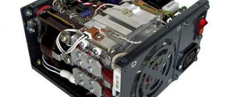
Scheme of an inverter semi-automatic welding machine.
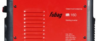
Maximum electrode diameter
Essentially the same characteristic of the operating current range. Sometimes, due to illiteracy or malicious intent, the diameter of the electrode is indicated, which will not be able to cook with the stated maximum current. Sometimes it’s the other way around: the maximum diameter of the electrode is indicated, which clearly does not reach the value of the declared welding current.
The latter option is occasionally a glimpse into the conscience of deceptive suppliers. They indicate the short-circuit current as the maximum current. But the maximum working diameter of the electrode is still indicated honestly.
Duty cycle, also known as PV (on period), also known as PN (payload)
PV is indicated by two numbers. The first is current strength. The second is the percentage of time. For example, “130A-50%” means that this device with a current of 130A can cook half the time. And the same amount of time will remain idle, waiting for cooling to operating temperature. If measurements are carried out at the maximum current of the device, the first digit is omitted, leaving only the percentage indicator. For example, if a device with a rating of 160A has the entry “30%” opposite “PV”, this means that with a current of 160 amperes it can operate 30% of the time, and 70% will cool down.
That's right. It only remains to add that the domestic GOST R IEC 60974-1-2004 does not establish a single mandatory method for measuring the PN indicator for MMA devices.
“The standard does not apply to limited-duty manual arc welding power supplies that are designed primarily for use by non-professionals.”
The European methodology, set out in the EN60974-1 standard, suggests measuring on a load stand at an ambient temperature of 40C only until the first shutdown due to overheating. The result obtained is referred to a 10-minute period. It turns out that the thermal protection worked after 3 minutes, the cycle of the device at this current is 30%.
Methodology of the TELWIN concern. To date, it is used by most Chinese manufacturers (those that generally conduct such tests on their cars). The Italian concern itself, when measuring the PV of its devices using its own method, modestly indicates “TELWIN” after the indicator. The vast majority of Chinese manufacturers do not do this.
Finally, there is a Russian, also known as Soviet, methodology. In essence, it is closer to the TELWIN method: all intervals during the control period when the device was working are summed up. But the segment is taken not 10, but 5 minutes. And - most importantly - the device is first put into overheating protection mode, after which measurements begin.
As a result, the same device produces completely different percentages using all 3 methods! Naturally, the most modest “numbers” are obtained using the European method, and the most impressive ones – up to 2 times or more – using the Telwin method.
External characteristics of welding arc power sources
The external characteristic can be steeply dipping, gently dipping, rigid and gently increasing. In order for the welding arc to burn stably, its external characteristics must coincide with the current-voltage characteristics.
The type of external characteristic depends on the type of welding technology. For example, for gas shielded welding the characteristic must be either gently increasing or rigid. And for RDS welding or automatic submerged arc welding, the characteristic should be decreasing. Only if these conditions are met will the arc burn stably.
What determines the correct selection of the mode?
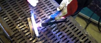
A correctly set idle mode ensures high-quality combustion of the electrode and a clearly defined droplet transfer of metal into the weld pool, forming a reliable connection with weld root penetration. The formation of spatter when igniting and breaking the arc is minimal; the surface of the parts being welded in the weld area requires almost no additional cleaning. One of the main signs of a correctly selected mode is the characteristic hissing sound when the arc burns.
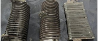
Three-phase welding rectifier with no-load voltage regulation by sectioning the turns of the transformer windings.
Some models of welding inverter have an additional protective function against electric shock to the welder at increased open circuit voltage. The device automatically reduces the voltage to a safe value when an emergency occurs and restores it when it disappears. Devices with increased open circuit voltage are used when welding with electrodes with refractory coating used to work with specific alloys.
Certain inverter models are equipped with a welding oscillator circuit for better arc ignition. Such devices were used on transformer welding machines with alternating and direct current. The oscillator converts the mains supply voltage into a voltage of 2.5-3 kV with a frequency of 150-300 kHz and outputs it to the output terminals in pulses lasting several tens of milliseconds. The oscillator consists of a step-up low-frequency transformer connected to an oscillating circuit and a spark gap with tungsten contacts. At the output there are capacitors that pass high-frequency currents and limit the low-frequency current from the welding machine.
Such devices also provide protection against electric shock. The power consumption of the oscillators is 250-300 W, which slightly increases the total power consumption of the welding inverter. Oscillators can be purchased as a separate unit or made independently.
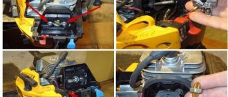
Possible malfunctions and their causes
The causes of problems with the inverter may arise due to:
- malfunction of the inverter itself;
- unsatisfactory condition of welding cables and device power circuit.
Functionality of the welding inverter.
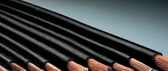
Thermal deformation and voltage at the output of the device are inextricably linked. Due to voltage surges, the temperature of the arc changes, the metal either does not warm up to the required temperature, or burns out, forming slag and pores. Troubleshooting methods depend on the problem found. The simplest reason may be poor contact in the connections of the welding cables with alligator clips and plugs for connecting to the inverter. It leads to the appearance of deformations during welding. Typically, such a defect manifests itself in sharp non-periodic jumps in the welding current, spontaneous attenuation of the arc, which can lead to poor-quality connections, deformation and stress when welding parts from uneven heating.
The solution is simple and can be done independently. To eliminate it, you need to remove the protective insulating handles, disconnect the cable and inspect the connection points. If there are oxides and traces of heating, the surfaces must be cleaned with emery cloth and assembled, carefully tightening the connecting bolts. Cables with broken or broken wires and damaged insulation must be replaced with similar ones. It is better to keep the cable length the same. Many inverter models are designed for a strictly defined inductive reactance load and can change the operating parameters when the cable length changes.
The next reason may be a malfunction of the device itself. To determine the operability of the device, it is necessary to measure the voltage at the output terminals of the inverter and the voltage in the supply network with the device. At normal mains voltage, a low voltage at the inverter output will indicate a malfunction of the device. It is better to entrust inverter repair to specialists from the service center.
If the voltage at the inverter output is within acceptable limits at normal supply voltage, you should carefully check the supply voltage supply circuit to the device from the power supply input point or meter. The minimum power consumption of devices in welding mode is within 4-5 kW. The required cross-section of copper supply wires for such power must be at least 2.5 mm 2 with a long-term permissible operating current of 25 A throughout the entire power circuit. A cable with a smaller cross-section will heat up quickly and the voltage loss on it will increase.
It is imperative to check the quality of all connections along the power supply circuit. Weak twisting or other types of poor-quality connections can also create problems during welding work and lead to fire. Detachable connections from a plug-socket pair must be of a new type with an increased diameter of electrically conductive pins on the plugs. Old type forks cannot withstand the load under long-term operating conditions. Sockets must also be of the appropriate type. The length of the power supply lines cannot be more than 50 m, unless otherwise specified in the technical documentation for the device.
In rural areas, abnormal operation of inverters is often observed due to overloaded common power lines and low network voltage.
If, when trying to ignite an arc, the supply voltage drops to an unacceptably low value at the input point, this indicates insufficient capacity of the common line and its overload.
Sometimes voltage stabilizers can help in such a situation. The effectiveness of stabilizers also depends on several reasons and is not always justified. The total power consumption of the kit from the power supply network will be the power of the welding device plus losses in the stabilization device. Electricity costs will increase, overload of common lines will increase, which will further reduce the input voltage.
Before deciding to use such a device in conjunction with welding equipment, it is advisable to contact the electrical network with a written statement about poor-quality power supply.
general information
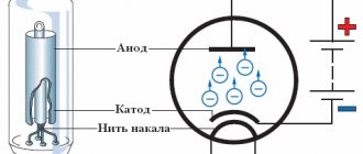
First, some general information about the welding arc.
An arc is a powerful electrical discharge that forms between the base metal and the end of the electrode. The welding arc generates high-temperature heat that is sufficient to weld most metals. To ignite the arc, an external current source is required. In general terms, the main power sources for welding are transformers, rectifiers, generators and inverters. Simply put, welding machines are transformer, rectifier or generator types. As well as an inverter welding machine. But within the framework of this article we will give more information, since the sources for powering the welding arc have many features.
Next, we will tell you what welding power sources exist, what their characteristics are and what requirements are placed on them.
Four types of converters
The main difference between welding arc power sources, which determines their technical characteristics, weight, dimensions and scope of application, is the difference in the principle of electric current conversion.
The following types of sources exist:
- transformers;
- rectifiers;
- converters;
- inverters.
Generators, the so-called units, stand apart. These machines are not secondary, but primary sources of energy; they do not convert power from a city or industrial network in one way or another, but generate it themselves.
As a rule, units are built on the basis of an internal combustion engine - gasoline or diesel. The former are cheaper, the latter have greater power and service life.
Welding current type: direct (DC) or alternating (AC)
Cooking with constant (or direct, in English - DC) current is simpler: it is easier to hold the arc. Therefore, 99.9% of modern MMA inverter machines produce constant welding current.
But among transformers, previously the majority were AC devices.
Alternating current (in English - AC) is used for welding non-ferrous metals. But not with MMA devices, but with TIG devices. Therefore, an MMA welding inverter that produces alternating current is a rarity.
DOMOSTROYPlumbing and construction
- home
- Connect with us
- Thursday, December 12, 2022 1:08
- Author: Sereg985
- Comment
- Category: Construction
- Link to post
- https://firmmy.ru/
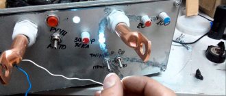
You can test the welding inverter to see what it is capable of. We take the most affordable TIG welding inverter. I will give an example of a device in the photo there IN 256T/ IN 316T.
If you look at the table, it shows where the idle speed is located in the form of an indication. On such devices, the idle speed is programmed by a computer. When you select the desired mode, the idle current is automatically set. It can be checked with a regular voltmeter at the ends of the power wires in the on state. That is, on the holder and the crocodile. The voltage drop should not deviate by more than five volts when igniting the arc and welding.
For example, if you ate a Chinese state employee, you will not find information about idle speed at all. Plus the Amperes are too high. In fact, some won’t even handle Uoni 13/55 electrodes. And why all? This electrode requires an idle current of 70 volts at 80 amps. And such welding machines are designed in such a way that as the current increases, the voltage also increases. In other words, at the highest current they will give you 90 volts. The voltage even before the secondary winding is controlled by a unit that converts the high voltage into the primary winding. Then, under the influence of electromagnetic force, it is transmitted to the secondary winding. The tension removed from her passes on. If the voltage at the input of the primary winding is low, then the output will be low.
Let's consider the primitive VD-306M U3. At low currents of 70-190 A, the voltage is 95 volts plus or minus 3 volts. At high currents of 135-325 A, the idle current is 65 volts plus or minus 3 volts. Moreover, it is stable in all current ranges. No matter how you twist the crank and change the amps to your heart's content, the idle speed will not decrease.
What am I getting at if the welding inverter does not weld well at low currents, the reason is in the control unit described above. As some say, install an additional choke or a ballast at the output. We turn the current up to full and adjust it at the ballast. The extra amperes will be taken over and the idle speed will remain unchanged.
Just for fun, check your welding machine. Throw the probes from the voltmeter onto the power cables and try to cook. See how the voltage drops. I myself personally cooked on a home network with an Interskol 250A inverter using 3mm UONI 13/45 electrodes with reverse polarity. As soon as I didn’t twist the amps properly and couldn’t ignite them, but the MP-3s burned, be healthy from the first touch.
When purchasing equipment, read in the passport how much idle current the device produces and at what currents. If this is not professional equipment, you will not be able to adjust the idle speed in any way. If not the method described above. You are unlikely to find such information on the unit body itself. Manufacturers usually hide it with big names and current strength.
Version: IP protection class
The IP protection class indicates the performance of electrical devices in relation to solid objects (first digit) and liquids (second digit).
You can determine the degree of protection of the device visually. If a device with IP21 has all the ventilation slots completely open, then with IP22 they are already covered on top with protruding visors. And on a device with IP23, these visors almost completely cover the cracks.
The degree of protection IP24 and higher is technically difficult and makes no sense.