A spotter is a modification of a welding machine that is used to perform car body repairs. Such work, as a rule, requires special knowledge of the structure of the car. Certain places in it often cannot be leveled from the inside. This is where this device helps. Due to the high cost of factory models, craftsmen are often interested in how to make a spotter with their own hands from a welding machine.
Spotter, its application and design
This tool is used to level out car dents when repairs from the outside are not possible. It can heat up part of the metal, and the damage to the body will be minor.
In particular, it is used for the following purposes:
- body straightening;
- leveling the surface of the body without the need to disassemble it.
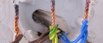
The enormous and irreplaceable benefit of this device lies in its use for leveling body parts when access to certain parts is limited due to the specific structure of the car. When straightening damaged parts of the body, a special device fastener is welded to the deformed surface and then pulls it out. It should also be noted that the spotter is capable of heating the metal during operation, and this facilitates rapid leveling, obtaining rigidity and the desired shape.
There are several schemes by which the device can be assembled. For such purposes, not only a welding machine can be used, but also an old battery, microwave oven, inverter or transformer. It is not difficult to make a welding machine from a battery with your own hands.
The work of this design consists of point-by-point pulling of the damaged part according to the principle of a hammer.
It looks like this:
- the return hammer of the device is fixed to the body using a welding pulse;
- The handbrake of the device must be pulled along the guide towards you, while the support washer remains in place.
The simplest spotter has 2 modes:
- temporary, when a ring is fixed to the surface;
- welding - light welding of the electrode to the surface is used when the device is attached to the car.
Opening opportunities
The advantages of resistance welding are sufficient to make it attractive to those who intend to launch mass production of products or repair equipment at a professional level.
- Good quality welded joint. It is ensured by the stability of the parameters of the welding current and pressure exerted on the parts being joined.
- High speed of the process. It takes seconds to apply a suture. This is especially important when it comes to performing a large amount of work.
- Operational simplicity. A properly manufactured resistance welding machine does not require special skills to use, and even a semi-skilled specialist can master the process.
- The use of a spotter is justified when repairing automobile bodies. This device simplifies not only the welding process, but also the straightening of damaged parts.
The main obstacle to widespread adoption of the technology is the high cost of equipment. This gives many people the idea of making a resistance welding machine on their own.
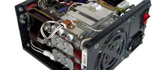
Inverter based spot welding
Do-it-yourself contact welding from an inverter is the most common type of homemade spotter for straightening.
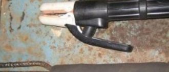
There are many ways to assemble this device. This type of spotter is very similar to resistance welding and is its modification. But its design has a distinctive feature - it does not contain pincers. That is why it can be considered an analogue of electric arc welding, in which current passes through the car body. One welding contact is attached to the surface, and the second is the nozzle and rod.
Inverter device
The main part of the device is a gun, which can be made from a similar device for construction glue or from semi-automatic welding. Many people are interested in how to assemble a puller with their own hands. The scheme is quite simple.
What you need
It is not worth starting to solve such a problem without the necessary theoretical knowledge and practical skills. In words it all looks relatively simple. But if you know how to solder and know how to rewind the transformer coils correctly, you can try it. To do this you will need certain materials and tools.
- Copper wire of a certain cross-section. Its cross-section and quantity can only be determined by performing preliminary calculations.
- Material for making a tire. At worst, you can get by with the same wire, but it is more advisable to purchase a ready-made product.
- Varnish to create an insulating layer on the wires and good insulating tape.
- Multimeter for taking the necessary measurements.
- Soldering supplies – soldering iron, flux, solder, etc.
Of course, you will have to purchase a ready-made welding inverter.
Specifications
The reverse hammer for body repair, made from an inverter, has a number of features. Technical characteristics of different models may differ, but their functions and purposes are similar.
Both homemade and factory-made devices, which have industrial purposes, have their own important functions:
- attaching washers to the surface using a spotter;
- welding occurs spotwise using an electrode, which stretches the surface of the car;
- the ability to warm up parts, align them and cool them;
- the simple design of the device makes it easy to use;
- two operating modes - one short-term with time regulation, and the second constant;
- the presence of an automatic temperature control system, which consists of turning off the device and cooling the part at high temperatures, as well as turning on welding if necessary.
Theoretical and practical assistance
The number of turns can be calculated using this formula: N = 50/S. Where N is the number of turns, S is the core area in cm2. To simplify the task, it is recommended to use a ready-made calculator program. They can also be found online. For example, the OER program. This will help avoid mistakes and simplify the task. Since we are talking about designing equipment based on a ready-made inverter, you should first measure the parameters of the primary coil, make calculations, and only then begin manufacturing the secondary winding.
How to work as a spotter with metal
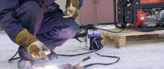
There is a technology for working with such a device, which has been used by craftsmen for a long time. It is used for car body work, eliminating deformed parts in hard-to-reach places. As a rule, such work is carried out on car doors and fenders in order not to completely remove such parts. The technology can be used wherever there is inward deformation of the surface.
Sometimes novice craftsmen are interested in how to make a homemade battery and spotter. Spot welding from a battery is performed by applying current to an electrode, welding it to the surface, leveling the surface with a gun, and tapping a perimeter around the damaged area with a hammer to fix it in place. Thanks to this method, the deformed part can be quickly aligned and returned to its original position. You need to pull it in carefully.
After leveling, the deformed surface is ground until the welding points from the fastening are removed and the surface becomes smooth. Do not forget about the mandatory grounding of the device. The negative terminal must also be removed from the battery.
The technology for working with a spotter looks like this:
- the damaged surface must be cleaned until the first appearance of “bare” metal;
- a negative contact is attached to the deformed surface;
- the electrode is welded to the working surface;
- pulling the damaged surface to the desired location;
- the welded electrode is removed from the surface with rotational movements;
- cleaning the surface from welding work and preparing it for putty.
To work with such a device, regardless of whether it is factory-made or home-made, you must have minimal experience with welding. It is important to follow the rules for working with such a device. This will allow you to straighten the damaged surface quickly, efficiently and, most importantly, safely. A spotter is an indispensable tool for deformed car surfaces that require spot repairs. You can assemble such a device yourself and not spend money on expensive factory models.
Making pliers
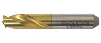
Only when the transformer is ready does it make sense to start making contact clamps. Their design primarily depends on the nature of the work for which the equipment will be used. The gripper design will depend on its drive system and the expected size of the parts to be connected. An important part of the pliers are the contact tips. If the thickness of the sheet being welded is small, it is quite acceptable to use copper tips from a soldering iron. It is better if you purchase and install ready-made tips - they are available for sale and are convenient because they have a special shape that is well suited for the job. But if we are talking about a steel sheet of 0.5 mm or more and it is intended to apply connecting seams of considerable length, it is recommended to equip the tips with rollers.
Secondary winding
Selecting parameters
DIY laboratory power supply
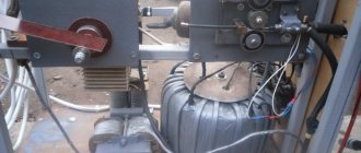
When remaking a CT, the main attention should be paid to the parameters of the secondary winding, which determine the output characteristics of the device (its load current, in particular). In this case, it is important to select a bus cross-section that would provide a current density of about 8 A/mm² (with a cross-sectional area of about 120 mm²). Since it is very difficult to handle such a thick busbar when winding on a torus, they are most often limited to a value of 80 mm².
Note! The specified cross-section can be obtained by putting together several wires of slightly less thickness.
To facilitate the conditions for converting a CT into a point unit, it is advisable to pre-calculate the amount of wire required for rewinding it. After this, it will be possible (based on the space occupied by the winding) to decide whether it will fit into the free space remaining on the torus or not.
Important! In the case where the new winding does not fit into the torus, the old secondary coil will have to be completely disassembled (dismantled).
To make it easier to handle new wires during the winding process, it is recommended to wrap them with fabric-based insulating tape. To determine the exact number of turns that affect the output voltage, we recommend using the test winding method with a small-section wire in insulation.
Since the winding in this case is not connected to the load, the cross-section of the test wire is not very important. Experience has shown that during rough tests it is sufficient to use no more than 10 turns. After winding them, the transformer should be connected to the network and the voltage produced by the test coil should be measured, after which it is divided by the number of turns. The result is a figure indicating the number of turns required to produce one volt of output.
Since in this case it is necessary to obtain 6 Volts, multiplying the number obtained from the test connection by 6, we obtain the required number of turns.
In order to make a new device with your own hands, you must first calculate the amount of wire required for rewinding the CT. After this, it will be possible (based on the space occupied by the bus winding) to determine whether it will fit into the free space remaining on the torus.
Winding diagrams and placement
The connection diagram and the order of placement of the “secondary” depend on the type of core selected. Given the toroidal base of the CT that we have declared, it is more convenient to divide it into two half windings connected in series (3 Volts each).
In order to increase the load capacity (increase the welding current), you can make two windings of 6 Volts each and connect them in parallel. In this case, the output voltage will not change, and the load current can be doubled. This design option allows us to solve the problem of the large cross-section of the secondary bus, which can then be reduced by half.
Various types of connections of such windings are shown in the picture below.
Secondary connection circuits
The order in which they are connected is very important to obtain the required output parameters, and mistakes made in this case can lead to completely different indicators. So, in particular, if you make a mistake during installation and turn on two windings in opposite directions, as a result they will be short-circuited to one another and will produce zero voltage at the output, which is equivalent to a short circuit.
At the ends of ready-made secondary windings, special tips should be equipped by crimping.
Control circuit
To control the welding process, short pulses are used, generated in a special electronic circuit. When manufacturing a spotter based on an old unit, it is also necessary to provide a control unit that allows switching a significant output current.
To solve this problem, manually generated pulses are applied to the primary winding of the CT (the simplest control circuit is shown in the figure below).
Simple switching diagram
The disadvantages of such management include:
- Using the button shown in the figure, the mains voltage is switched, which is extremely dangerous;
- When mechanical contacts open, strong sparking occurs;
- Even if you replace the mains switch with a traction relay from the starter, controlled by a push-button mechanism, then such a circuit, despite the improvement, will still be unfinished.
Note! To implement the traction principle, it is allowed to use a combination of “powerful starter plus automotive relay” (and the latter can be of any brand).
When this combination is selected, the relay is activated when a voltage of 12 Volts is applied, and its switching causes the power contactor to operate. However, this control option is not without drawbacks, since in this case it is not possible to precisely control the impact interval (pulse width).
For those who know the basics of electronics and know how to handle a soldering iron, a more complex in design, but reliable in operation, electronic control circuit will be suitable (see photo below).
Thyristor control circuit
Here, operating pulses are supplied to the input winding of the CT from an electronic device - a thyristor, which opens when voltage is applied to its control electrode. The capacitor (C1) included in its circuit, with the button contact open, is charged through the elements V1-V4 of the diode bridge. When the button is pressed, the capacitance is discharged through resistor R1 and directly through the thyristor control electrode circuit, which causes it to turn on.
The electronic device will remain on until the capacitor is completely discharged (this interval can be adjusted with variable resistor R1). For the subsequent start operation, the button must first be released and then pressed again (its shutter speed determines the welding interval).
Transformer T1 can be of any type (with a voltage on the secondary winding of 12 Volts). The parameters of the thyristor must satisfy the operating conditions, that is, allow it to operate at voltages up to 400 Volts and currents of at least 50 Amperes. An electronic product of the T132-50 brand is quite suitable for these purposes.
In the final part of the review, we would like to remind you that welding equipment of the “spotter” type is most often in demand for body repair and similar work with sheet metal. In this regard, when choosing the output power of a home-made unit, it is necessary to take into account the thickness of the sheet material with which you will mainly be working.
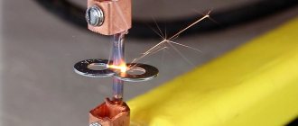
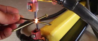
Operating principle and design of resistance spot welding machines
After the metal plates that need to be welded are clamped by the electrodes, a short-term pulse of high-power electric current is applied to them. The pulse time is selected depending on the characteristics of the two metals being welded. Typically the discharge lasts from 0.01 to 0.1 fractions of a second.
Construction of a resistance spot welding machine.
When the pulse passes through the metal, the parts melt and a common liquid core forms between them and until it hardens, the surfaces to be welded must be held under pressure.
After a few moments, the liquid core crystallizes and a strong ingot of their two elements is obtained.
The pressure on the parts is gradually removed; if it is necessary to forge the sheets to a deeper thickness relative to each other, at the final stage the pressure increases, this will allow achieving maximum homogeneity of the metals at the welding site.
Important! To improve the quality of welding, it is important to pre-treat the surfaces of parts to remove oxide film or corrosion.
Welding process: manufacturing diagram
When assembling the device yourself, it is necessary to take into account the Joule-Lenz law (Q = I² X R X t), which states: thermal energy is released in conductors in a certain amount in proportion to their resistance, the coefficient of current strength in time and squared.
Experts advise paying due attention to the homemade mechanism, taking into account the large loss of energy in thin wires, and using a high-quality electrical circuit.
Types of contact welding:
- Suture
- Spot
- Butt
In spot welding, the device technology is based on the thermal effect of current. This ensures welding of the part at one or several points.
The size and structural features of the electrode contact surface differ. This affects the strength level of the connections.
We list several existing stages in spot welding technology:
- The mating components are connected and placed between the electrodes of the device. The components should be positioned tightly against each other. This will ensure the formation of a sealing belt near the molten core, which will prevent hot metal from splashing out during the pulse.
- The next step is heating the parts. They become thermoplastic, which makes it possible to modify them. It is possible to make high-quality welding at home, the main thing is to follow the key principles of the technology: maintain the speed of movement of the electrodes, a constant pressure value and a tight connection of all parts.
When current passes, a pulse is generated, which heats the welding machine and allows the metal to melt at the points of contact with the electrodes.
Then a common core of liquid consistency 4-12 mm in diameter is formed. After the current is applied to the parts, they will hold securely until the core cools and its further crystallization.
Domestic use of homemade spot welding allows you to ensure mechanical strength of metal seams without high costs, but does not allow you to create hermetic seams.
The state standard regulates safety precautions, work processes and welding equipment.
Weigh everything properly
Planning to make a resistance welding machine with your own hands. First, objectively evaluate your knowledge and capabilities, as well as the entire scope of upcoming work. This will avoid wasting time and money. It will be a shame to realize somewhere in the middle of the journey that everything was in vain, and it would have been easier to buy ready-made equipment. But if everything works out, you will be rewarded with significant monetary savings and the pride of knowing that you were able to cope with a difficult task.