Electron beam welding (also known as electron beam welding, electron beam welding, EBW) is a fairly rapidly developing type of welding. With its help you can weld almost anything: high-strength alloys, chemically active metals, and refractory materials. In short, the scope of application is very large.
In this article we will describe in detail what EBW welding is, what are the advantages and disadvantages of this technology, and what features need to be taken into account.
Content
- The essence of the electron beam welding process
- Parameters and indicators of ELS
- Electron beam welding installation diagram
- Electron beam welding technology
- ELS technique
- Technological methods of EBW
- Equipment for electron beam welding
- Classification and composition of installations for EBW
- Electron ray guns
- Electron ray gun power supplies
The essence of the electron beam welding process
Electron beam welding (EBW) is carried out in a vacuum, using a focused stream of electrons with a high specific power, which acts on the welded edges, melting them.
Welding of thin metal is carried out with a flow of approximately 104 W/cm2. For single-pass welding of large metal thicknesses, about 200-300 mm, a power of 105-106 W/cm2 is required.
The high concentration of energy in the beam flow makes it possible to obtain narrow and deep welds with a minimal heat-affected zone and high mechanical properties, while welding is performed at high speeds.
Peculiarities
Since the technology is not the simplest, it is accompanied by some nuances that need to be taken into account to fully understand the essence. The first nuance is that all welding takes place in a vacuum environment. This makes the surface of the parts perfectly clean. And the second nuance is that the parts heat up to extremely high temperatures. As a result, we get a seam of minimal thickness, which also forms quickly. This is very good.
Thanks to these features, EBW welding can be used when welding a wide variety of metals. Two parts may have different thickness, composition and even melting point. The seam will still be of high quality. The minimum thickness for welding is 0.02 millimeters. And the maximum is 100 millimeters. The range is very large, most parts can be welded. That's all you need to consider.
Parameters and indicators of ELS
The characteristics of the electron beam measured during the welding process include beam current I, accelerating voltage U, focusing system current Iph, working distance (distance from the center of the focusing system to the welding edges) L, beam convergence angle a, laser beam speed V Beam power Q=IU, W. These parameters are set during welding and with their help you can determine the specific power Qу, W/cm2 and the diameter of the electron beam d:
Qу=IU/(3.14d24).
If welding is carried out in a pulse-periodic mode, then the average beam power can be determined by the formula:
Qср=I и Uft,
where Ii is the beam current strength in the pulse, A; U—accelerating voltage, V; f—pulse frequency, Hz; t—pulse duration, s. The welding speed in pulse mode is determined by the formula:
Vi=b(LK)f,
where K is the point overlap coefficient (usually in the range of 0.5-0.9); b is the diameter of the weld point, cm.
The most common values of electron beam parameters for welding are in the following limits: Q=1-120 kW, at U=25-120 kV, a=1-5°, t=20-200 mm; Vi=0.1-3 cm/s; d=0.1-3 mm, f=1-100 Hz, t=5-100 ms, K>10.
Electron beam welding installation diagram
Electron beam welding, in most cases, is performed with a vertical or horizontal beam in vacuum chambers, the size of which depends on the size of the product being welded. The volume of welding chambers can range from 0.1 to hundreds of cubic meters. The figure below shows the ELS installation diagram:
An electron gun located in the chamber (or on the camera) creates an electron beam. A vacuum is created in the chamber, which can vary widely: 1-10-3 Pa. But even in low vacuum (1 Pa), the oxygen content is 17 times, and nitrogen is 10 times less than in ultra-pure argon, therefore, protecting the welding zone in a vacuum chamber is very effective.
Electron beam welding technology
ELS technique
Electron beam welding can be performed in the down position with a vertical beam, and it can also be used when welding vertical and horizontal seams on a vertical wall.
In this case, the electron beam will be horizontal. Welding in the lower position is recommended when welding steels up to 40mm thick, or when welding titanium and aluminum alloys up to 80mm thick. Using a horizontal beam, you can weld metal up to 400 mm thick with through penetration. For a single-pass EBW, the design must take into account the deep penetration of the beam into the metal. The figure on the left shows common examples of electron beam welded structures.
The gap in the joint is 0.1-0.2 mm when welding metal up to 30 mm thick. When welding metal with a thickness of more than 30 mm, the gap is 0.3 mm. In general, the beam diameter should be larger than the gap.
Technological methods of EBW
When electron beam welding there are a number of special techniques that can improve the quality of the weld:
1. Welding with an inclined beam (beam deflection is about 5-7°) allows you to reduce defects in the weld such as pores and discontinuities in the metal, and also allows you to achieve uniform crystallization of the metal.
2. To alloy the weld metal and to replenish the elements that evaporate during the welding process, an additive is used.
3. To improve the removal of gases and steam from the metal, welding is carried out on a dispersed pad of granules or finely chopped welding wire. The thickness of the gasket is 40mm.
4. Welding into a narrow groove (0.8-8 mm) is performed in the lower position due to the surfacing of filler material into the rectangular groove of the edges.
5. Welding is carried out in tandem from two electron guns of different power. A more powerful gun performs penetration, and a less powerful gun forms the root of the channel, or the tail part of the bath.
6. To check the positioning of the beam and clean the edges being welded, preliminary passes with the beam are used.
7. Double-sided welding is performed simultaneously on both sides of the joint or sequentially, approximately half the thickness of the metal.
8. During the welding process, scanning of the electron beam is used, thereby creating better gas and hydrodynamic conditions for channel formation. The development can be longitudinal, transverse, X-shaped, along a circle, along an ellipse, etc. Double refraction of the beam during the development process allows for better welding of the root of the seam and reduces defects in it.
9. To weld two or more joints simultaneously, beam splitting is performed using a deflection system.
10. To control heat transfer into the weld, modulation of the beam current is used, most often with a frequency of 1-100 Hz.
11. At the end of welding, a so-called “cosmetic” pass is performed. This is a repeated pass, which is designed to eliminate weld defects, both external and internal.
Application area
To connect:
- steel of different classes with metal thickness up to 8 cm;
- titanium or light alloys with a thickness of no more than 10 cm;
- copper alloys - up to 2 cm.
High quality welding:
- thin-walled or thick-walled structures intended for a separate purpose;
- large structures made of homogeneous metal, when their processing at high temperatures is extremely difficult.
The scientists who designed such industrial installations assure that there are no problematic materials for EBW, among those known to modern science.
Calculation of some parameters of the ELS mode
The welding speed required for the beam to penetrate to a depth H is determined by the formula:
Vst<4Q/(3.14dHSbp)
For titanium welding, the following values have been experimentally established: Q = 54 kW, H = 10 cm, Vw = 0.5 m/s, d = 2.7 mm, Skip = 50 kJ/cm3.
The figure below shows the experimental dependence of the thermal efficiency nt of penetration on the parameter Q/(HVw) for welding steels:
The relationship between the parameters of the electron beam and geometric characteristics is determined by the formula:
B=(4nпntQd/3.14VsvHSpl)1/2, where B is the width of the weld.
Equipment for electron beam cooking
Classification and composition of installations for electron beam welding
According to the degree of specialization, installations for electron beam welding are divided into universal and specialized. According to the pressure in the working chamber: with high vacuum (with a pressure in the chamber less than 1 Pa), with an intermediate vacuum (with a pressure in the chamber from 1 to 10 Pa) and for welding in shielding gases or in the atmosphere (with a pressure of 1000-100000 Pa).
According to the method of creating a vacuum in the welding zone, a distinction is made between chamber electron beam installations (when the product is located inside the working chamber) and with local evacuation (vacuum is created only in the welding zone).
The figure above shows the structure of a chamber installation for EBW. Any such installation necessarily includes an electron beam gun, a power source, a vacuum creation system, and a control system.
Electron ray guns
Electron ray guns produce an electron beam. The main components of the gun are shown in the figure on the left. This is an electron generator and beam conduction system. The electron generator consists of a cathode, a control electrode and an anode. The beam transmission system includes adjusting, focusing and deflection coils.
Cathodes can be filament (thermal cathodes) or plasma. Thermal cathodes are made of tungsten, tantalum, alloys of these metals with rhenium, or lanthanum hexaboride.
High-voltage insulators are made of ceramics, glass or special plastics. The anode and control electrode are made of copper or stainless steel.
An accelerating voltage is placed between the anode and cathode. The beam is controlled by changing the potential of the control electrode relative to the cathode.
Electron beam gun (EBG) power supplies
The ELP power supplies include an accelerating voltage source, as well as power supplies for the control electrode, cathode, adjusting coil, focusing coil and deflection coil. The accelerating voltage source includes a regulating element on the primary or secondary side of the high-voltage transformer with or without frequency conversion of the supply voltage. The figure below shows a diagram of accelerating voltage sources.
The voltage is regulated by thyristors or transistors on the primary side. Regulation on the secondary side occurs using special high-voltage lamps. To protect the ELP from electrical breakdowns, accelerating voltage sources are equipped with automatic restart devices. This equipment allows you to successfully perform welding with frequent breakdowns without a significant reduction in welding quality.
Accelerating voltage sources are located in a tank with transformer oil, which, among other things, plays the role of a cooling medium. There are also accelerating voltage sources up to 60 kV, in which air or compound is used as cooling.
For galvanic isolation, the control electrode power supply uses high-purity transformers or a shared LED/phototransistor interconnected by a light guide. To ensure constant parameters of the beam transmission system, the power of the adjusting, focusing and deflection coils is carried out using a current regulator.
Vacuum system of electron beam installation ELU
The ELU vacuum system is necessary to ensure the required pressure in the ELU and in the working chamber. In most cases, the pressure is 0.1-0.001 Pa in the EBL and 0.01-10 Pa in the working chamber. The ELP is isolated from the working chamber by means of a special vacuum valve, which opens during welding. The figure on the right shows a diagram of a typical vacuum chamber of an electron beam installation.
In practice, vane or spool pumps and units based on them are used as mechanical pumps with a maximum pressure of 0.1-10 Pa. They also use double-rotor pumps. If it is necessary to create a high vacuum, high-vacuum steam-oil or turbomolecular pumps are used.
Electron beam installation control system
The control system must ensure the following tasks:
1. Software control of the functioning of all installation systems.
2. Monitoring and diagnostics of the operation of all installation systems.
3. Monitoring and controlling the position of the electron beam in relation to the weld joint.
4. Monitoring and management of spatial, energy and temporal characteristics of the electron beam.
5. If the installation operates as part of a flexible production system, ensure communication with a higher-level control system.
The elementary basis of the control system is the microprocessor. All software control can be carried out by one sufficiently powerful computer, or by a system of computers, among which there are central and local microprocessors, on which local control of one or several devices is performed.
Types of lasers
Laser welding of aluminum alloys, copper, stainless steel and other metals and materials can be carried out with different lasers. The devices come in solid-state and gas-based types. Each type is selected according to the purpose of the equipment. But we should not forget about the important characteristics of each type.
Solid State
Laser welding of copper, aluminum, stainless steel, silver, plastic and even glass is carried out using a solid-state laser. It requires the main component - a ruby rod; it can also be made of glass with neodymium. Typically this element is located inside the lighting chamber.
At the moment when light with high power is supplied to the chamber at a certain frequency, excitation of atoms occurs in the crystal at that moment. All this leads to the emission of light, which has waves of the same length. The end parts of the rod element consist of reflecting mirrors. One of them is partially transparent. Energy comes out through it in the form of laser radiation.
It is worth noting! Solid-state lasers have low power. This figure can vary from 1 to 6 kW.
Gas
Gas-type lasers are considered more powerful and productive devices, in which a gas mixture acts as an active body. However, laser welding of titanium, copper, aluminum, and stainless steel, which is carried out using these devices, has important features:
- Gas is pumped from the cylinders using a pump. For this, a gas discharge tube is used.
- An electric current discharge occurs between the electrodes, which causes energetic excitation of the gas mixture.
- In the end zones of the gas-discharge tube there are special mirrors through which laser beams are passed.
- When performing laser welding of frames, car bodies and other products, the electrodes are connected to a power source.
- The cooling process of laser devices is carried out by a water system.
But still, gas devices have a significant drawback - large dimensions. But laser units that have transverse gas pumping are small in size. General power indicators of equipment start from 20 kW and above. Thanks to this, metals with a thickness of up to 2 cm can be welded at speeds of up to 60 meters per hour.
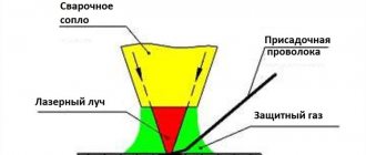
Laser welding of silver, copper, aluminum, titanium, stainless steel and other metals is carried out under atmospheric conditions. It requires a vacuum, but the molten metal must be protected from the influence of air. Gases, usually argon, are used for this. Due to the fact that there is a high thermal power of the beam on the surface of the element being welded, increased evaporation of the metal occurs. The vapors are ionized, resulting in scattering and screening of the laser beam.
Laser welding of glass, plastics and products made of various metals, during which gas mixtures are used, is characterized by the fact that in addition to the shielding gas, plasma suppression gas penetrates into the welding area. The material used is helium, which is much lighter than argon; it will not scatter the laser beam. To simplify the process, many experienced welders often use combined gas mixtures that have plasma suppression and protective properties.
Features of gas dynamic lasers
Gas-dynamic units have high power indicators. Carbon monoxide acts as the active body. It is heated to 3000 K and passed through a Laval nozzle. At the exit from the nozzle, a rapid decrease in pressure and gradual cooling of the gas mixture are observed.
Weld defects in electron beam welding
The most characteristic defects in electron beam welding with non-through penetration are cavities not filled with metal, 5-10 mm in size, and periodic lack of fusion of the weld root.
Defects occur due to changes in the penetration depth. The depth of penetration can be different for the same specific power of the electron beam and it depends on the welding speed. The lower the welding speed, the greater the penetration depth.
The figure on the side shows the formation of a cavity inside the weld in the weld channel. As the welding speed decreases, the depth of the channel increases, and at the exit from the channel there is a possibility of its slamming with liquid metal and the formation of a cavity in the weld metal.
The formation of periodic defects at the root of the weld in the form of non-fusion, the amplitude of which can reach about 3-4 mm, is explained by periodic vibrations of the liquid metal in the weld pool and the periodic bridging (clogging) of the channel associated with these vibrations.
During clogging, the beam energy is spent for some time on “drilling” the layer of liquid metal, i.e. work is being done to form a certain fraction of the channel depth, which actually leads to a decrease in the channel depth by exactly this fraction.
Characteristic defects of electron beam welding are also the deviation of the penetration channel from the line of edge joint. This happens due to the deflection of the electron beam due to the influence of a magnetic field on it. This phenomenon is observed when welding steels with residual magnetization. To prevent such a defect, the products being welded are demagnetized before welding begins.
Advantages
Electron beam welding is a high-tech type of welding work and is used, accordingly, in complex and high-precision industries.
Its main drawback is essentially one - the beam welding installation is difficult to manufacture and install, therefore it is very expensive - about several million. Its use is justified and cost-effective where the cost of the final product for all other production factors correlates with the cost of the welding installation.
As a rule, these are industries that require ultra-high quality joints, including metals whose welding by other methods is difficult or impossible. These include chemically active metals (aluminum, magnesium and especially titanium), as well as superhard and refractory ones.
Electron beam welding has other advantages. It has a high efficiency, which entails the consumption of less energy that needs to be spent on one operation (compared to contact or electric arc welding).
Electron beam welding has a minimum heating spot area - up to 0.00001 sq. cm, less - only for laser welding. It has a maximum power at the heating point - up to 100 million watts per square meter. cm (higher only for laser).
The peculiarity of electron beam technology makes it possible to degas the weld, making it possible to weld chemically active metals - niobium, molybdenum, titanium, zirconium. It is possible to weld very refractory metals, such as tungsten, since the main energy is spent on heating the contact point.
It becomes possible to finely regulate the penetration depth and achieve precision accuracy. Electron beam welding occurs practically without human intervention; the installation operator only sets and controls the parameters.
It has a high speed - up to 5 cm/sec, and it is possible to produce parts of very small sizes and complex configurations, and to weld in hard-to-reach places.
https://youtube.com/watch?v=0n0tlDQWeN4
When electron beam welding occurs, a seam with a “dagger” cross-section appears, deep and narrow, with minimal fusion. The amount of angular deformation is reduced to a minimum.